Honeywell SmartLine ST 700 User Manual
Pressure transmitters
Hide thumbs
Also See for SmartLine ST 700:
- User manual (202 pages) ,
- Installation manual (9 pages) ,
- Quick start installation manual (24 pages)

Subscribe to Our Youtube Channel
Related Manuals for Honeywell SmartLine ST 700


Summary of Contents for Honeywell SmartLine ST 700
- Page 1 SmartLine Pressure Transmitters ST 700 User’s Manual 34-ST-25-44 Revision 13 September 2022 Honeywell Process Solutions...
- Page 2 In no event is Honeywell liable to anyone for any indirect, special, or consequential damages. The information and specifications in this document are subject to change without notice.
- Page 3 This manual is a detailed how to reference for installing, piping, wiring, configuring, starting up, operating, maintaining, calibrating, and servicing Honeywell’s family of ST 700 SmartLine pressure transmitters,Standard and basic models. Users who have a Honeywell ST 700 SmartLine pressure transmitter configured for HART protocol or Honeywell’s Digitally Enhanced (DE) are referred to the ST 700 Series HART/DE Option User’s Manual, Document # 34-ST-25-47.
- Page 4 Smart Field Communicator Model STS 103 Operating Guide, # 34-ST-11-14. Patent Notice The Honeywell ST 700 SmartLine pressure transmitter family is covered by one or more of the following U. S. Patents: 5,485,753; 5,811,690; 6,041,659; 6,055,633; 7,786,878; 8,073,098; and other patents pending.
- Page 5 Symbol Descriptions and Definitions The symbols identified and defined in the following table may appear in this document. Symbol Definition ATTENTION: Identifies information that requires special consideration. TIP: Identifies advice or hints for the user, often in terms of performing a task.
- Page 6 Symbol Description ®: The Factory Mutual Approval mark means the equipment has been rigorously tested and certified to be reliable. The Canadian Standards mark means the equipment has been tested and meets applicable standards for safety and/or performance. The Ex mark means the equipment complies with the requirements of the European standards that are harmonised with the 94/9/EC Directive (ATEX Directive, named after the French "ATmosphere EXplosible").
-
Page 7: Table Of Contents
3.3.1 Safety Integrity Level (SIL) ................... 11 Installation and Startupfor the ST 700 Standard Transmitter ............12 Installation Site Evaluation ..................... 12 Honeywell MC Toolkit......................12 Display Installation Precautions ..................... 12 Mounting ST 700 Standard Transmitters ................13 4.4.1 Summary......................... 14 4.4.2... - Page 8 Operation_ST 700 Standard Transmitter ..................42 Overview ..........................42 Three-Button Operation ......................42 5.2.1 The Basic Display Menu ....................44 5.2.2 Data Entry ........................48 5.2.3 Editing a Numeric value....................49 5.2.4 Selecting a new setting from a list of choices ..............50 Two-Button Operation ......................
- Page 9 11.3.1 Safety Integrity Level (SIL) ..................126 Installation and Startup_ST 700 Basic Transmitter ..............127 12.1 Installation Site Evaluation ....................127 12.2 Honeywell MC Toolkit......................127 12.3 Display Installation Precautions ................... 127 12.4 Mounting_ST 700 Basic Transmitter ................... 128 12.4.1 Summary........................
- Page 10 13.5 Monitoring the Standard Displays ..................207 13.5.1 Standard Display ......................208 Maintenance_ST 700 Basic Transmitter .................. 209 14.1 Overview ..........................209 14.2 Preventive Maintenance Practices and Schedules ..............209 14.3 Inspecting and Cleaning Barrier Diaphragms ..............209 14.4 Replacing the Communication Module ................212 14.5 Replacing the Meter Body ....................
- Page 11 List of Figures Figure 1 – ST 700 Standard Transmitter Major Assemblies ..............4 Figure 2 – ST 700 Standard Transmitter Electronics Housing Components ..........4 Figure 3 –ST 700 Standard Transmitter - Typical Name Plate ..............5 Figure 4 – ST 700 Standard Transmitter - Typical Bracket and Flange Mounted Installations ..... 14 Figure 5 - ST 700 Standard Transmitter - Typical Flush Mounted Installation ........
- Page 12 Figure 41 – ST 700 Basic Transmitter - Major Assemblies ..............120 Figure 42 – ST 700 Basic transmitter Electronics Housing Components ..........120 Figure 43 – ST 700 Basic Transmitter - Name Plate ................121 Figure 44 – ST 700 Basic Transmitter - Typical Bracket Mounted and Flange Mounted Installations ................................
- Page 13 ST 700 SmartLine Pressure Transmitters User’s Manual Revision 13 Page xiii...
- Page 14 List of Tables Table 1 – ST 700 Standard andf Basic model types ................2 Table 2 – Features and Options_ST 700 Standard transmitter..............3 Table 3 – Available Display Characteristics .................... 6 Table 4 – ST 700 Standard transmitter - Basic Display Diagnostics Messages ........10 Table 5 - ST 700 Standard Transmitter - Mounting Bracket procedure ..........
- Page 15 Table 41 – ST 700 Basic Transmitter - HART Failsafe and Write Protect Jumpers ......206 Table 42 – Head Bolt Torque Values ....................211 Table 43 – ST 700 Basic Transmitter - Fault Conditions and Recommended Corrective Actions..220 Table 44 –...
-
Page 17: St 700 Transmitter Series
ST 700 Transmitter Series Overview SmartLine pressure transmitter ST 700 family conists of a series of ST 700 standard transmitter models and a series of ST 700 basic transmitter models. Note: The entire manual is broadly classified in two sections for standard and basic transmitters. -
Page 18: Table 1 - St 700 Standard Andf Basic Model Types
Table 1 – ST 700 Standard andf Basic model types Smart Line Pressure ST700 Transmitter Configuration Standard Models Basic Models Dual head DP STD720/730/770 STD725/735/775 Dual head GP STG730/740/770 STG735/745/775 Inline GP STG73L/74L/77L/78L/79L STG73S/74S/77S/78S/79S Inline flush GP STG73P STG73SP Dual head AP STA722/740 STA725/745 Inline AP... -
Page 19: Introduction To The St 700 Standard Transmitter
Introduction to the ST 700 Standard Transmitter This section is an introduction to the physical and functional characteristics Honeywell’s family of the ST 700 Standard transmitters. Features and Options The ST 700 standard transmitter is available in a variety of models for measuring Differential Pressure (DP), Gauge Pressure (GP), and Absolute Pressure (AP). -
Page 20: Physical Characteristics
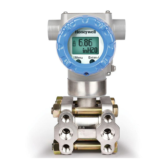
2.1.1 Physical Characteristics As shown in Figure 1, the ST 700 standard is packaged in two major assemblies: the electronics housing and the meter body. The elements in the electronic housing respond to setup commands and execute the software and protocol for the different pressure measurement types. Figure 2 shows the assemblies in the electronics housing with available options. -
Page 21: Functional Characteristics
Honeywell Multi-Communication (MC) Toolkit (not supplied with the transmitter) can facilitate setup and adjustment procedures. Certain adjustments can be made through an Experion Station or a Universal Station if the transmitter is digitally integrated with Honeywell’s Experion or TPS/TDC 3000 control system. -
Page 22: Safety Certification Information
Zero and Span adjustments are possible in ST 700 standard transmitter with the optional 3 button and two-button assemblies. You can also use the Honeywell MC Toolkit or other third-party hand-held configurator to make adjustments to the ST 700 standard transmitter. Alternately, certain adjustments can be made through the Experion or Universal Station, if the transmitter is digitally integrated with a Honeywell Experion or TPS system. -
Page 23: Optional Integrated Two-Button Assembly (Standard Display)
Optional Integrated Two-Button Assembly (Standard Display) The standard display does not support all the transmitter configuration parameters and has limited features. The optional Integrated two-button assembly for the standard display provides the following features and capabilities: • Menu and enter key functionality. •... -
Page 24: Application Design For The St 700 Standard Transmitter
Application Design for the ST 700 Standard Transmitter Overview This section discusses the considerations involved with deploying a Honeywell ST 700 standard transmitter in a process system. The following areas are covered: • Safety. • Input and output data. •... -
Page 25: Diagnostic Messages
3.2.1 Diagnostic Messages The transmitter standard diagnostics are reported in the two basic categories listed in Table Problems detected as critical diagnostics drive the analog output to the programmed burnout level. Problems detected as non-critical diagnostics may affect performance without driving the analog output to the programmed burnout level. -
Page 26: Safety
Table 4 – ST 700 Standard transmitter - Basic Display Diagnostics Messages Critical Diagnostics Non-Critical Diagnostics (Warning Conditions) (Failure Conditions) Sensor Comm Timeout No DAC Compensation No DAC Calibration Meter Body Critical Failure No Factory Calibration Tamper Alarm Electronic Module Diag Failure PV Out of Range Meter Body Unreliable Comm Config Data Corrupt... -
Page 27: Safety Integrity Level (Sil)
“prior use” justification by the end user or diverse technology redundancy in the design. Refer to the Honeywell SmartLine Safety Manual, Document # 34-ST-25-37, for additional information. ST 700 SmartLine Pressure Transmitters User’s Manual Revision 13... -
Page 28: Installation And Startupfor The St 700 Standard Transmitter
Evaluate the site selected for the ST 700 standard transmitter installation with respect to the process system design specifications and Honeywell’s published performance characteristics for your particular model. Some parameters that you may want to include in your site evaluation are: •... -
Page 29: Mounting St 700 Standard Transmitters
Mounting – ST 700 Standard Transmitter ST 700 SmartLine Pressure Transmitters User’s Manual Revision 13 Page 13... -
Page 30: Summary
The ST 700 standard transmitter models, except flush mounts and those with integral flanges, can be attached to a two-inch (50 millimeters) vertical or horizontal pipe using Honeywell’s optional angle or flat mounting bracket; alternately you can use your own bracket. flush-mount models are attached directly to a process pipe or tank by a one-inch weld nipple. -
Page 31: Flush Mounting - St 700 Standard Transmitter
4.4.2 Flush mounting – ST 700 Standard Transmitter To mount a flush mounted model, cut a hole for a 1” standard pipe in the tank or pipe where the transmitter is to be mounted. Weld the 1” mounting sleeve to the wall of the tank or to the hole cut on the pipe. -
Page 32: Mounting Dimensions
4.4.3 Mounting Dimensions Refer to Honeywell drawing number 50049930 (Dual Head), 50049931 (In-Line), 50049932 (flange mount) 50049933 (Extended flange), 50049934 (Remote Seal) and 50049936 (flush mount pressure transmitter) for detailed dimensions. Abbreviated overall dimensions are also shown on the Specification Sheets for the transmitter models. This section assumes that the mounting dimensions have already been taken into account and the mounting area can accommodate the transmitter. -
Page 33: Bracket Mounting Procedure
4.4.4 Bracket Mounting Procedure If you are using an optional bracket, start with Step 1. For an existing bracket, start with Step 2. 6. Position the bracket on a 2-inch (50.8mm nominal diameter, 2.38” 1. Refer to Figure (60.4mm) actual OD) for a horizontal or vertical pipe, and install a “U” bolt around the pipe and through the holes in the bracket. -
Page 34: Figure 7 - St 700 Standard Transmitter - Inline Model Mounted To An Optional Bracket
Figure 7 – ST 700 Standard Transmitter - Inline Model Mounted to an Optional Bracket 3. Loosen the set screw on the outside neck of the transmitter one (1) full turn. 4. Rotate the electronics housing a maximum of 180 left or right from the center to the position you require, and tighten the set screw using a 4mm metric socket head wrench. -
Page 35: Mounting Transmitters With Small Absolute Or Differential Pressure Spans
4.4.5 Mounting Transmitters with Small Absolute or Differential Pressure Spans To minimize positional effects on calibration (zero shift), take the appropriate mounting precautions for the respective transmitter model. Ensure that the transmitter is vertical when mounting models STA722 and STA72L. You do this by leveling the transmitter side-to-side and front-to-back. -
Page 36: Flange Mounting
4.4.6 Flange Mounting Figure 10 shows a typical tank-flange mount installation, with the transmitter flange mounted to the pipe on the wall of the tank. On insulated tanks, remove enough insulaiton to accommodate the flange extension. When flange-mounting to a tank, note the following: •... -
Page 37: Remote Diaphragm Seal Mounting Information
4.4.7 Remote Diaphragm Seal Mounting Information The combination of tank vacuum and high pressure capillary head effect should not exceed nine (9) psi (300mmHg) absolute. For insulated tanks, be sure to remove enough insulation to accommodate the flange extension. The end user is responsible for supplying a flange gasket and mounting hardware suitable for the service condition of the transmitter. -
Page 38: Piping The St 700 Standard Transmitter
Piping the ST 700 Standard Transmitter ST 700 SmartLine Pressure Transmitters User’s Manual Page 22 Revision 13... -
Page 39: Piping Arrangements
4.5.1 Piping Arrangements Piping arrangements vary depending upon process measurement requirements and the transmitter model. For example, a differential pressure transmitter comes with double-ended process heads with ¼-inch NPT connections, which can be modified to accept ½-inch NPT through optional flange adapters. -
Page 40: Transmitter Location
4.5.2 Transmitter Location The following are suggested connections based on what is being processed by the system. Table 8 – ST 700 Standard Transmitter - Suggested Connection Locations Process Suggested Location Description Gases Above the gas line. The condensate drains away from the transmitter. Liquids Below but near the elevation of This minimizes that static head effect of the... -
Page 41: General Piping Guidelines
4.5.3 General Piping Guidelines • When measuring fluids that contain suspended solids, install permanent valves at regular intervals to blow-down piping. • Blow-down all lines on new installations with compressed air or steam, and flush them with process fluids (where possible) before connecting these lines to the transmitter Meter body. •... -
Page 42: Procedure To Install Flange Adapters
4.5.4 Procedure to Install Flange Adapters The following procedure provides the steps for removing and replacing an optional flange adapter on the process head. Refer to Figure 13. This procedure does not require that the meter body be removed from the electronics housing. -
Page 43: Overview
4.6.1 Overview The transmitter is designed to operate in a two-wire power/current loop with loop resistance and power supply voltage within the operating range shown in Figure Figure 14 – ST 700 Standard Transmitter - Operating Ranges Loop wiring is connected to the transmitter by simply attaching the positive (+) and negative (–) loop wires to the positive (+) and negative (–) terminals on the transmitter terminal block in the electronics housing shown in Figure... -
Page 44: Figure 15 - St 700 Standard Transmitter - 3-Screw Terminal Board And Grounding Screw
Figure 15 – ST 700 Standard Transmitter - 3-Screw Terminal Board and Grounding Screw As shown in Figure 15, each transmitter has an internal terminal to connect it to earth ground. Optionally, a ground terminal can be added to the outside of the electronics housing. While it is not necessary to ground the transmitter for proper operation, doing so tends to minimize the possible effects of noise on the output signal and affords protection against lightning and static discharge. - Page 45 The positive and negative loop wires are connected to the positive (+) and negative (–) terminals on the terminal block in the transmitter electronics housing. Barriers can be installed per Honeywell’s instructions for transmitters to be used in intrinsically safe applications.
-
Page 46: Digital System Integration Information
4.6.2 Digital System Integration Information Transmitters that are to be digitally integrated to Honeywell’s Total Plant Solution (TPS) system will be connected to the pressure transmitter interface module in the Process Manager, Advanced Process Manager or High Performance Process Manager through a Field Termination Assembly. Details... -
Page 47: Wiring Variations
If you are using the transmitter with Honeywell’s TPS system, see PM/APM Smartline Transmitter Integration Manual, PM12-410, which is part of the TDC 3000 system bookset. -
Page 48: Wiring Procedure
4.6.4 Wiring Procedure 1. See Figure 15, above, for parts locations. Loosen the end cap lock using a 1.5mm Allen wrench. 2. Remove the end cap cover from the terminal block end of the electronics housing. 3. Feed loop power leads through one end of the conduit entrances on either side of the electronics housing. -
Page 49: Lightning Protection
4.6.5 Lightning Protection If your transmitter includes the optional lightning protection, connect a wire from the Earth Ground Clamp (see Figure 15) to Earth Ground to make the protection effective. Use a size 8 AWG or (8.37mm ) bare or green covered wire for this connection. ST 700 SmartLine Pressure Transmitters User’s Manual Revision 13 Page 33... -
Page 50: Supply Voltage Limiting Requirements
4.6.6 Supply Voltage Limiting Requirements If your transmitter complies with the ATEX 4 directive for self-declared approval per 94/9EC, the power supply has to include a voltage-limiting device. Voltage must be limited such that it does not exceed 42V DC. Consult the process design system documentation for specifics. ST 700 SmartLine Pressure Transmitters User’s Manual Page 34 Revision 13... -
Page 51: Process Sealing
4.6.7 Process Sealing The ST 700 SmartLine pressure transmitter is CSA-certified as a Dual Seal device in accordance with ANSI/ISA–12.27.01–2003, “Requirements for Process Sealing Between Electrical Systems and Flammable, or Combustible Process Fluids.” ST 700 SmartLine Pressure Transmitters User’s Manual Revision 13 Page 35... -
Page 52: Explosion-Proof Conduit Seal
4.6.8 Explosion-Proof Conduit Seal When installed as explosion proof in a Division 1 Hazardous Location, keep covers tight while the transmitter is energized. Disconnect power to the transmitter in the non-hazardous area prior to removing end caps for service. When installed as non-incendive equipment in a Division 2 hazardous location, disconnect power to the transmitter in the non-hazardous area, or determine that the location is non- hazardous before disconnecting or connecting the transmitter wires. -
Page 53: Startup - St 700 Standard Transmitter
Startup – ST 700 Standard Transmitter ST 700 SmartLine Pressure Transmitters User’s Manual Revision 13 Page 37... -
Page 54: Overview
4.7.1 Overview This section identifies typical start up tasks associated with several generic pressure measurement applications. It also includes the procedure for running an optional analog output check. ST 700 SmartLine Pressure Transmitters User’s Manual Page 38 Revision 13... -
Page 55: Startup Tasks
The actual steps in a startup procedure vary based on the type of transmitter and the measurement application. In general, the procedures in this section are based on using Honeywell MC Toolkit to check the transmitter input and output under static process conditions, and make adjustments as required initiating full operation with the running process. -
Page 56: Output Check Procedures
4.7.3 Output Check Procedures The Output Check comprises the following procedures: • The loop test procedure checks for continuity and the condition of components in the output current loop. • The Trim DAC Current procedure calibrates the output of the Digital-to-Analog converter for minimum (0%) and maximum (100%) values of 4mA and 20mA, respectively. -
Page 57: Constant Current Source Mode Procedure
4.7.4 Constant Current Source Mode Procedure Figure 16 – ST 700 Standard Transmitter - Current Loop Test Connections 1. Refer to Figure 16 for test connections. Verify the integrity of electrical components in the output current loop. 2. Establish communication with the transmitter. For these procedures, the values of components in the current loop are not critical if they support reliable communication between the transmitter and the Toolkit. -
Page 58: Operation_St 700 Standard Transmitter
Operation – ST 700 Standard Transmitter Overview This section provides the information and processes involved for both Digitally Enhanced (DE) and HART operation using the three-button basic and two-button standard options for the ST 700 standard transmitter. Three-Button Operation The ST 700 standrad transmitter has optional three-button interface that provides a user interface and operation capability without opening the transmitter. -
Page 59: Table 9 - Three-Button Option Functions
Table 9 – Three-Button Option Functions Physical Basic Display Action Button • Increment Scroll to previous menu item in an active list. Left • Scroll through alphanumeric list to Previous menu Item desired character (ex. for entering Tag names or numeric values). •... -
Page 60: The Basic Display Menu
5.2.1 The Basic Display Menu The basic display menu is implemented as one long single-level menu and will “wrap around” when it reaches the start or end of the menu. Operation is as follows: Press the button to call up the menu. ... -
Page 61: Table 10 - The Basic Display Menus
Table 10 – The Basic Display Menu Submenu/Selection/ Menu Description Action Value Entry Adjust the LCD contrast level. Range from » (1) to »»»»»»»»» LCD Contrast »»»»» Default: »»»»»»»(7) Pressure Pressure Units Select Process Variable (PV) to Percent Output PV Display be shown on the Loop Output display from list. - Page 62 32.0 seconds Press to enter menu selection Disabling sets the loop output and Enabled and to NAMUR burnout levels to the Honeywell Disabled levels select from list to enter Fast Speed of Response Filter Perf Fast SOR...
- Page 63 Submenu/Selection/ Menu Description Action Value Entry Allows the user to specify a single breakpoint as the low flow cutoff point. Single Breakpt This item is only available when the Transfer Function is set to Square Root. Flow Cutoff Uses a dual slope formula to determine the low flow cutoff point.
-
Page 64: Data Entry
5.2.2 Data Entry Data entry is performed from left to right. Select a character / digit by pressing or buttons, and ▒ then press to advance to the next character position to the right. Select the cross-hatch character <<... -
Page 65: Editing A Numeric Value
5.2.3 Editing a Numeric value Editing of a numeric value is a digit-by-digit process, starting with the left-most digit. 1. Press to begin the edit process. 2. The basic display will show the current value of the item on the lower line, left justified. ... -
Page 66: Selecting A New Setting From A List Of Choices
5.2.4 Selecting a new setting from a list of choices Use the procedure described below to select a new setting for parameters that present a list of choices (e.g., PV Display, Pressure Units, etc.). 1. Press to begin the edit process. a. -
Page 67: Two-Button Operation
Two-Button Operation The ST 700 standrad transmitter has an optional two-button interface that provides an user interface that supports in both English and Russian Language and operation capability without opening the transmitter. Figure 18 shows the location of the two-button option and the labels for the buttons. –... -
Page 68: The Standard Display Menu
5.3.1 The Standard Display Menu The standard display menu is implemented as one long single-level menu, after entering into menu mode, and will “wrap around” when it reaches the end of the menu. To enter menu mode select PV display mode. Operation is as follows: ... - Page 69 Choose appropriate engineering units from list for calibration and ftH2O68F writing LRV/URV gf/cm2 This selection determines the inH2O39F units of the values shown on the inH2O60F following menu items: • inH2O68F Enter LRV • inHg0C Enter URV • kgf/cm2 Press to Set LRV •...
- Page 70 This selection allows the loop zero output 4mA value to be DAC Zero Trim trimmed. [5ZEROTR] Press to DAC Zero Trim Note: You must connect a current enter menu Note: Loop must be selection meter to the transmitter to monitor removed from the loop output.
- Page 71 Press to enter menu Perform an input calibration LRV Corrects selection Calibration Methods correction by applying process [11LRVCOR] input at the configured LRV level. Press to initiate action Press to enter menu Perform an input calibration URV Corrects selection Calibration Methods correction by applying process...
- Page 72 Configure the desired Press to performance for the Output enter menu Speed of Response Filter. Select selection from: Standard SOR: excellent Filter Selection STDSOR speed of response to input Menu to [18FLTSEL] FASTSOR changes with optimal noise select from performance Fast SOR: fastest list speed of response to input...
- Page 73 Press to enter menu selection When “User Configuration” is to select Low Flow Cut Off selected for Low Flow Cutoff Breakpoint ##.# number. Mode, enter the desired to enter [23%FLOW] breakpoint value. and shift to the next digit to the right Performs the correction of measured static pressure value to...
- Page 74 Available for AP models only. Executing this selection corrects input pressure to the Barometric Press to Standard value when the enter menu pressure input is open to the One point field offset selection Barometric Correct atmosphere. Calibration Method. [27BARCOR] The live value of the pressure Press ...
- Page 75 Not normally used. See Field Calibration for Alternate Ranges, below. Executing this selection corrects input pressure to be at or near the Cal Low Point without compromising LRV and URV corrections. A trial-and-error Press to approach using different Cal Two-point Field enter menu Adjust Ratio values and repeated...
- Page 76 Display rotation enumerations: Press to When “ON” is selected for 1- 2s enter menu 2- 4s Rotation Interval, enter the selection 3- 6s desired interval time. Rotation Interval 4- 8s Automatic display screen rotation Menu to [34ROTINT] 5- 10s in seconds: select from 6- 12s...
- Page 77 m3/hr kg/hr MT/hr L/sec L/hr SCFH Press to enter menu gal/hr selection bbl/hr Screen1 Flow Units Choose appropriate engineering Igal/hr Menu to [37FUNIT] units from list. select from SCFD list gal/min to enter lb/hr lb/min SCFM MSCFH MMSCFH Custom Press ...
- Page 78 Press to enter menu selection When “Custom” selected for to select Screen1 Pressure Units, enter Screen1 Pressure the custom unit name. alphanumeric Custom Unit character. to enter [41PCUNIT] Character string of pressure custom unit text for display and shift to x = any Alphanumeric value.
- Page 79 ftH2O68F gf/cm2 inH2O39F inH2O60F inH2O68F Press to inHg0C enter menu kgf/cm2 selection Screen2 Pressure Units Choose appropriate engineering mbar Menu to [45PUNIT] units from list. mmH2O4C select from mmH2O68F list mmHg0C to enter Torr mH2O4C cmH2O4C Custom m3/hr kg/hr MT/hr L/sec...
- Page 80 Press to enter menu selection Value of the flow custom Menu to Screen2 Flow Scaling engineering unit corresponding to ######## the LRV of the transmitter. select [48FSCLLO] The limits are: number. to enter -999999 to 999999 and shift to the next digit to the right Press ...
- Page 81 Press to When “Custom” selected for enter menu selection Screen2 Pressure Units, enter the Screen2 Pressure Scaling Menu to Screen2 Pressure High value. Scaling High ######## Value of the pressure custom select [52PSCLHI] engineering unit corresponding to number. ...
- Page 82 m3/hr kg/hr MT/hr L/sec L/hr SCFH Press to enter menu gal/hr selection bbl/hr Screen3 Flow Units Choose appropriate engineering Igal/hr Menu to [55FUNIT] units from list. select from SCFD list gal/min to enter lb/hr lb/min SCFM MSCFH MMSCFH Custom Press ...
- Page 83 Press to enter menu selection When “Custom” selected for to select Screen3 Pressure Units, enter Screen3 Pressure alphanumeric the custom unit name. Custom Unit character. Character string of pressure to enter [59PCUNIT] custom unit text for display and shift to x = any Alphanumeric value.
- Page 84 ftH2O68F gf/cm2 inH2O39F inH2O60F inH2O68F Press to inHg0C enter menu kgf/cm2 selection Screen4 Pressure Units Choose appropriate engineering mbar Menu to [63PUNIT] units from list. mmH2O4C select from mmH2O68F list mmHg0C to enter Torr mH2O4C cmH2O4C Custom m3/hr kg/hr MT/hr L/sec...
- Page 85 Press to enter menu selection Value of the flow custom Menu to Screen4 Flow Scaling engineering unit corresponding to ######## the LRV of the transmitter. select [66FSCLLO] The limits are: number. to enter -999999 to 999999 and shift to the next digit to the right Press ...
- Page 86 Press to When “Custom” selected for enter menu selection Screen4 Pressure Units, enter the Screen4 Pressure Scaling Menu to Screen4 Pressure High value. Scaling High ######## Value of the pressure custom select [70PSCLHI] engineering unit corresponding to number. ...
-
Page 87: Standard Display Abbreviations
5.3.2 Standard Display Abbreviations: Table 13 – ST 700 Basic Transmitter - The Standard Display abbreviations Abbreviation Meaning Out of Range PRSPAN Push reduce span Wrng Mo Wrong Mode Illegal Illegal Value Wrt Err NVM write error Too Hi Value/Parameter Too High Too Lo Value/Parameter Too Low LRV Hi... -
Page 88: Data Entry
5.3.3 Data Entry Data entry is performed from left to right. Select a character / digit by pressing buttons, and then press to advance to the next character position to the right. Select the cross-hatch character ▒ to terminate the entry or if the final character is already a space character, just press <<... -
Page 89: Editing A Numeric Value
5.3.4 Editing a Numeric value Editing a numeric value is a digit-by-digit process, starting with the left-most digit. 1. Press to begin the edit process. 2. The standard display will show the current value of the item on the lower line, left justified. ... -
Page 90: Selecting A New Setting From A List Of Choices
5.3.5 Selecting a new setting from a list of choices Use the procedure described below to select a new setting for parameters that present a list of choices (e.g. PV display, Pressure Units, and so forth.). 1. Press to begin the edit process. a. -
Page 91: Basic And Standard Display Operations
Basic and Standard Display Operations After removing and connecting the standard display please wait upto 15 seconds for the device to detect the presence of display as all the processing happens in the communication board. The standard display does not have any microcntroller. Note: If existing communication board is updated with the new firmware that supports Russian display, please make sure to use the new standard display with Russian support to avoid seeing unexpected characters on the display. -
Page 92: Editing A Numeric Value
5.4.1 Editing a Numeric value Editing of a numeric value is a digit-by-digit process, starting with the left-most digit. 1. Press to begin the edit process: • The basic and standard display will display the current value of the item on the lower line, left justified. -
Page 93: Selecting A New Setting From A List Of Choices
5.4.2 Selecting a new setting from a list of choices Use the procedure described below to select a new setting for parameters that present a list of choices (e.g. PV display, Pressure Units, etc.). 1. Press to begin the edit process. a. -
Page 94: Three Button Operation With No Display Installed
Three-Button Operation with no Display Installed When there is no display installed, the buttons can be used to perform a Zero or Span adjustment of the ST 700 standard transmitter. Caution should be taken to insure these adjustments are only made when the correct input pressures are applied. -
Page 95: Zero Adjustment
5.5.1 Zero Adjustment This adjustment is the same as performing a Set LRV using the display. 1. Connect a current meter or voltmeter as shown in Figure 16 to monitor the PV output of the transmitter. 2. Using an accurate pressure source, apply pressure equivalent to the transmitter LRV. ↓... -
Page 96: Span Adjustment
5.5.2 Span Adjustment This adjustment is the same as performing a Set URV using the display. 1. Connect a current meter or voltmeter as shown in Figure 16 to monitor the PV output of the transmitter. 2. Using an accurate pressure source, apply pressure equivalent to the desired Upper Range Value of the transmitter. -
Page 97: Changing The Default Failsafe Direction
Changing the Default Failsafe Direction Transmitters are shipped with a default failsafe direction of upscale. This means that the transmitter output will set the current output to upscale failsafe (maximum output) upon detection of a critical status. You can change the direction from upscale failsafe to downscale failsafe (minimum output) by moving the top jumper located in the electronics module. -
Page 98: And Analog Differences
5.6.1 DE and Analog Differences Failsafe operation is different between DE and analog operation: • Analog operation – Upscale failsafe drives the transmitter output to 21.8mA. Downscale failsafe drives the transmitter output to 3.8mA. • DE operation – Upscale failsafe causes the transmitter to generate a + infinity digital signal. Downscale failsafe causes the transmitter to generate a –... -
Page 99: Procedure To Establish Failsafe Operation
5.6.2 Procedure to Establish Failsafe Operation The failsafe direction display accessible via the toolkit shows only the state of the jumper as it correlates to analog transmitter operation. Failsafe action for the DE control system may be configured to operate in a manner different from analog, as indicated by the state of the transmitter jumper. -
Page 100: Table 16 - St 700 Standard Transmitter - Hart And De Failsafe And Write Protect Jumpers
Table 15 – ST 700 Standard Transmitter - HART and DE Failsafe and Write Protect Jumpers Jumper Description Arrangements Failsafe = UP (High) Write Protect = OFF (Not Protected) Failsafe = DOWN (Low) Write Protect = OFF (Not Protected) Failsafe = UP (High) Write Protect = ON (Protected) Failsafe = Down (Low) Write Protect = On (Protected) -
Page 101: Table 17 - St 700 Standard Transmitter - Fieldbus Simulation And Write Protect Jumpers
Table 16 – ST 700 Standard Transmitter - Fieldbus Simulation and Write Protect Jumpers Jumper Description Arrangements Fieldbus Simulation Mode = OFF Write Protect = OFF (Not Protected) Fieldbus Simulation Mode = OFF Write Protect = ON (Protected) Fieldbus SIM Mode = ON Write Protect = OFF (Not Protected) 1. -
Page 102: Monitoring The Basic And Standard Displays For The St 700 Standard Transmitter
Monitoring the Basic and Standard Displays for the ST 700 Standard Transmitter This section describes the information shown on the operator screens of the basic and standard displays. ST 700 SmartLine Pressure Transmitters User’s Manual Page 86 Revision 13... -
Page 103: Basic Display_St 700 Standard Transmitter
5.7.1 Basic Display – ST 700 Standard Transmitter Figure 20 illustrates the basic display format with Process Variable (PV). • The PV value is user-configurable. This field has 7 characters. The maximum allowable numeric value is 9999999 or -999999. If fractional decimals are configured, the fractional positions will be dropped, as required. -
Page 104: Standard Display_St 700 Standard Transmitter
5.7.2 Standard Display – ST 700 Standard Transmitter • The PV value is user-configurable. This field has 6 characters. The maximum allowable numeric value is 999999 or -999999. o If fractional decimals are configured, the fractional positions will be dropped, as required. -
Page 105: Figure 21 - St 700 Standard Transmitter - Standard Display With Process Variable Format
Figure 21 – ST 700 Standard Transmitter - Standard Display with Process Variable Format ST 700 SmartLine Pressure Transmitters User’s Manual Revision 13 Page 89... -
Page 106: Maintenance_St 700 Standard Transmitter
Maintenance – ST 700 Standard Transmitter Overview This section provides information about preventive maintenance and replacing damaged parts. The topics covered in this section are: • Preventive maintenance of the meter body barrier diaphragms and process piping to the transmitter. •... -
Page 107: Figure 22 - St 700 Standard Transmitter - Dp Transmitter Head Disassembly
8. Inspect the barrier diaphragm for signs of deterioration, corrosion, and distortion. 9. If the diaphragm is distorted contact Honeywell for assistance. 10. Install a new gasket/O-ring in each process head. 11. Coat threads on the process head bolts with a suitable anti-seize compound, such as “Neverseize,”... -
Page 108: Figure 23 - St 700 Standard Transmitter - Head Bolt Tightening Sequence
Figure 23 – ST 700 Standard Transmitter - Head Bolt Tightening Sequence Table 17 – Head Bolt Torque Values ST 700 SmartLine Pressure Transmitters User’s Manual Page 92 Revision 13... -
Page 109: Replacing The Communication Module
Replacing the Communication Module The communication module includes a connector to the sensor ribbon cable and a connector to the optional display module. This section includes the procedure to replace the communication module. The transmitter does not have to be removed from service to replace the comm module. Please take appropriate steps to avoid ESD damage when handling the communication and display module assemblies. - Page 110 6. Carefully align and connect the Sensor Ribbon Cable to the connector “J4” at the bottom of the communication module. When installing the communication module in the next step, be careful not to pinch the Sensor Ribbon Cable. 7. Carefully, insert the communication module into the Electronics compartment. Ensure that the Sensor Ribbon Cable is not pinched.
-
Page 111: Replacing The Meter Body
17. Restore power if removed. 18. Check the settings of the transmitter Setup and display Setup parameters to make sure that the transmitter is configured correctly for your application. See the HART/DE User's Manual (ST 800 #34-ST-25-38, ST 700 #34-ST-25-44) for details on HART and DE transmitters. Refer to manual #34-ST-25-39 for additional information about Fieldbus transmitters. -
Page 112: Figure 26 - St 700 Standard Transmitter - Hardware Location To Remove The Meter Assembly
6. Loosen the two retaining screws, and remove the communications module assembly, and remove the communication module assembly from the electronics housing. 7. Disconnect the Sensor Cable from the communications Board. 8. Refer to Figure 26. Use a 2mm hex wrench to completely loosen the set screw on the outside of the housing to permit rotating the meter body. -
Page 113: Figure 27 - St 700 Standard Transmitter - Meter Body Reassembly
Figure 27 – ST 700 Standard Transmitter - Meter Body Reassembly 16. Use a torque wrench to gradually tighten nuts to torque rating in sequence shown in Figure Tighten head bolts in stages of 1/3 full torque, 2/3 full torque, and then full torque. Figure 28 –... - Page 114 20. Loosen the set screw ½- turn. 21. Rotate the housing to the desired position (Max. 180 in either direction), and tighten the set screw. 22. Carefully align and connect the Sensor Ribbon Cable to connector “J4” at the bottom of the communication module board.
-
Page 115: Calibration For The St 700 Standard Transmitter
For a transmitter operating in analog mode, you must calibrate its output signal measurement range using any compatible hand-held communicator or a local display. One calibration option is to use the Honeywell Smart Field Communicator (SFC). Refer to the Smart Field Communicator Operating Guide, Document # 34-ST-11-14 for calibration procedures. -
Page 116: Troubleshooting On The St 700 Standard Transmitter
However, this section covers the diagnostic messages that indicate critical conditions. Other than the critical conditions, additional detail is not provided. If you require assistance, contact your distributor or Honeywell Technical Support. All other messages are covered by the MC Toolkit Users’ Manual. Critical Diagnostics Screens The basic display will display the message CRITCAL FAULT on the top line of the LCD and the appropriate diagnostic text on the lower line. -
Page 117: Fault Conditions And Recommended Corrective Actions - Basic Display
8.2.1 Fault Conditions and Recommended Corrective Actions – Basic Display Table 18 – ST 700 Standard Transmitter - Fault Conditions and Recommended Corrective Actions for basic Display Recommended Corrective Condtion Analysis Action Fault. Use a HART, DE, or FF Cycle power to the transmitter. If communicator to read the detailed the problem continues to occur, A critical failure has... -
Page 118: Fault Conditions And Recommended Corrective Actions - Standard Display
8.2.2 Fault Conditions and Recommended Corrective Actions – Standard Display The standard dsplay will display the message FAULT on the top line of the LCD and the appropriate diagnostic text on the lower line. Table 19 – ST 700 Standard Transmitter - Fault Conditions and Recommended Corrective Actions Recommended Corrective Condtion... -
Page 119: Parts List_St 700 Standard Transmitter
Parts List – ST 700 Standard Transmitter Overview Individually saleable parts for the various transmitter models are listed in this section. Some parts are illustrated for identification. Parts are identified and listed in the corresponding tables as follows: • Individually saleable parts are indicated in each figure by key number callout. •... -
Page 120: Figure 29 - St 700 Standard Transmitter - Angle And Flat Bracket Parts
100- Process head gasket kit Figure 1-10 1000 Units Units Units 51452868-501 Gasket only, Process Head (12 PTFE packs) 12-24 24-48 51452868-502 Gasket only, Process Head (6 Viton Head 6-12 12-24 O’Rings) Figure 33 51452868-507 Gasket only, Process Head Graphite Gasket 6-12 12-24 (replacement only for existing graphite gasket) -
Page 121: Figure 30 - St 700 Standard Transmitter - Electronic Housing, Display End
Table 21 – ST 700 Standard Transmitter - Angle and Flat Bracket Parts (Refer to Figure Quantity Part Number Description Per Unit SS 304 Angle Bracket Mounting kit for all models except In- 30752770-603 line and flush mount transmitters. SS 304 Angle Bracket Mounting kit for all In-Line and flush 30752770-604 mount transmitters. -
Page 122: Table 23 - St 700 Standard Transmitter Major Assemblies
Table 22 – ST 700 Standard Transmitter Major Assemblies (Refer to Figure 31 Figure Quantity Part Number Description Per Unit 50049858-501 End Cap (Aluminum) 50049858-521 End Cap (Stainless Steel) 50049832-501 End Cap, Display (Aluminium) with window 50049832-521 End Cap, Display (Stainless Steel) with window 50075472-531 Terminal Assy HART/DE without Lightning protection 50075472-532... -
Page 123: Figure 31 - St 700 Standard Transmitter - Electronic Housing, Terminal Block End
Figure 31 – ST 700 Standard Transmitter - Electronic Housing, Terminal Block End ST 700 SmartLine Pressure Transmitters User’s Manual Revision 13 Page 107... -
Page 124: Figure 32 - St 700 Standard Transmitter - Major Assemblies
Figure 32 – ST 700 Standard Transmitter - Major Assemblies ST 700 SmartLine Pressure Transmitters User’s Manual Page 108 Revision 13... -
Page 125: Table 24 - St 700 Standard Transmitter Models Std720, 730 & 770
Table 23 – ST 700 Standard Transmitter Models STD720, 730 & 770 (Refer to Figure Qty/ Part Number Description Meter Body Gasket Kits 51452865-501 Glass Filled PTFE 51452865-502 VITON 51452865-503 100% PTFE 51452865-504 GRAPHITE Each Meter Body Gasket Kit includes: Gasket, Process Head Gasket, Flange Adapter O-Ring, Meter Body to Electronics Housing... - Page 126 Qty/ Part Number Description Bolt And Nut Kit 51452866-501 Carbon steel bolt and Nut Kit 51452866-502 Stainless Steel Bolt and Nut Kit with NACE Certificate 51452866-503 Stainless Steel Bolt and Nut Kit without NACE Certificate 51452866-504 B7M Bolt and Nut Kit 51452866-505 All Stainless Steel NACE Bolt and Nut Kit 51452866-506...
-
Page 127: Figure 33 - St 700 Standard Transmitter - St 700 Models Std720, 730, 770
Figure 33 - ST 700 Standard Transmitter - ST 700 Models STD720, 730, (Refer toTable 24) ST 700 SmartLine Pressure Transmitters User’s Manual Revision 13 Page 111... - Page 128 Table 24 – ST 700 Standard Transmitter - Parts for STG730, 740, 770 and STD720, 730, 770 and STA722, 740 Transmitter Body Figure 34 (Refer to Part Number Description Qty/Unit Process Head Assembly Kits with PTFE Gaskets 51452864-010 Carbon steel head (zinc plated) without side vent/drain 51452864-012 Carbon steel head (zinc plated) with side vent/drain 51452864-020...
- Page 129 Part Number Description Qty/Unit Bolt And Nut Kit 51452866-501 Carbon steel bolt and Nut Kit 51452866-502 Stainless Steel Bolt and Nut Kit with NACE Certificate 51452866-503 Stainless Steel Bolt and Nut Kit without NACE Certificate 51452866-504 B7M Bolt and Nut Kit 51452866-505 All Stainless Steel NACE Bolt and Nut Kit 51452866-506...
-
Page 130: Figure 34 - St 700 Standard Transmitter - Stg730, 740, 770 And Sta722, 740 Transmitter Body
Figure 34 – ST 700 Standard Transmitter - STG730, 740, 770 and STA722, 740 Transmitter Body ST 700 SmartLine Pressure Transmitters User’s Manual Page 114 Revision 13... -
Page 131: Figure 35 - St 700 Standard Transmitter - Inline Gauge And Inline Atmospheric Meter Body Bodies
Table 25 - ST 700 Standard Transmitter - Inline Gauge and Inline Atmospheric Meter Body Parts (See Figure 35) Part Number Description Qty/Unit Specify complete model ST Series replacement meter body (LAP/LGP number from nameplate model) Figure 35 – ST 700 Standard Transmitter - Inline Gauge and Inline Atmospheric Meter Body Bodies ST 700 SmartLine Pressure Transmitters User’s Manual Revision 13... -
Page 132: Figure 36 - St 700 Standard Transmitter - Extended Flange Design
Table 26 – ST 700 Standard Transmitter - Flange-Mounted Meter Body Parts – STF724, 732 Refer to Figure 36 Figure 37 Part Number Description Qty/Unit Specify complete model ST Series 700 replacement meter body number from nameplate Figure 36 – ST 700 Standard Transmitter - Extended Flange Design Figure 37 - ST 700 Standard Transmitter - Flush Flange Design ST 700 SmartLine Pressure Transmitters User’s Manual Page 116... -
Page 133: Figure 38 - St 700 Standard Transmitter - Pseudo Flange Design
Figure 38 - ST 700 Standard Transmitter - Pseudo Flange Design Figure 39 – ST 700 Standard Transmitter - Remote Seal Diaphragm ST 700 SmartLine Pressure Transmitters User’s Manual Revision 13 Page 117... -
Page 134: Figure 40 - St 700 Standard Transmitter - Flush Mount Meter Body
Figure 40 - ST 700 Standard Transmitter - Flush Mount Meter Body. Table 27 – ST 700 Standard Transmitter - Flush Mount Meter Body Parts (Refer to Figure Part Number Description Qty/Unit Specify complete model number Replacement meter body (flush from nameplate Mount model) 30756445-508... -
Page 135: Introduction_St 700 Basic Transmitter
10. Introduction – ST 700 Basic Transmitter 10.1 Overview This section is an introduction to the physical and functional characteristics Honeywell’s family of the ST 700 basic SmartLine pressure transmitters. If you are not sure which type of ST 700 you have, standrad or basic, please refer to... -
Page 136: Physical Characteristics
10.2.1 Physical Characteristics As shown in Figure 41 the ST 700 basic transmitter is packaged in two major assemblies: the electronics housing and the meter body. The elements in the electronic housing respond to setup commands and execute the software and protocol for the different pressure measurement types. Figure 42 shows the assemblies in the electronics housing with available options. -
Page 137: Functional Characteristics
An optional external 2-button assembly is available to set up and make adjustments to the transmitter. In addition, a Honeywell Multi-Communication (MC) Toolkit (not supplied with the transmitter) can facilitate setup and adjustment procedures. Certain adjustments can be made through an Experion Station if the transmitter is digitally integrated with Honeywell’s Experion. -
Page 138: Safety Certification Information
2-button and integrated two-button assemblies. See Figure 42 for the external 2-button assembly. You can also use the Honeywell MC Toolkit or other third-party hand-held configurator to make adjustments to the ST 700 basic transmitter. Alternately, certain adjustments can be made through the Experion or Universal Station, if the transmitter is digitally integrated with a Honeywell Experion or TPS system. -
Page 139: Optional Integrated Two-Button Assembly (Standard Display)
10.7 Optional Integrated Two-Button Assembly (Standard Display) The standard display does not support all the transmitter configuration parameters and has limited features. The optional Integrated Two-Button Assembly for the standard display provides the following features and capabilities: • Menu and enter key functionality. •... -
Page 140: Application Design_St 700 Basic Transmitter
11. Application Design – ST 700 Basic Transmitter 11.1 Overview This section discusses the considerations involved with deploying a Honeywell ST 700 basic transmitter in a process system. The following areas are covered: • Safety. • Input and output data. -
Page 141: Diagnostic Messages
11.2.1 Diagnostic Messages Transmitter standard diagnostics are reported in the two basic categories listed in Table Problems detected as critical diagnostics drive the analog output to the programmed burnout level. Problems detected as non-critical diagnostics may affect performance without driving the analog output to the programmed burnout level. -
Page 142: Safety Integrity Level (Sil)
“prior use” justification by the end user or diverse technology redundancy in the design. Refer to the Honeywell SmartLine Safety Manual, Document # 34-ST-25-37, for additional information. ST 700 SmartLine Pressure Transmitters User’s Manual Page 126... -
Page 143: Installation And Startup_St 700 Basic Transmitter
Evaluate the site selected for the ST 700 basic transmitter installation with respect to the process system design specifications and Honeywell’s published performance characteristics for your particular model. Some parameters that you may want to include in your site evaluation are: •... -
Page 144: Mounting_St 700 Basic Transmitter
12.4 Mounting – ST 700 Basic Transmitter ST 700 SmartLine Pressure Transmitters User’s Manual Page 128 Revision 13... -
Page 145: Summary
ST 700 basic transmitter models, except flush mounts and those with integral flanges, can be attached to a two-inch (50 millimeters) vertical or horizontal pipe using Honeywell’s optional angle or flat mounting bracket; alternately you can use your own bracket. Flush-mount models are attached directly to a process pipe or tank by a one-inch weld nipple. -
Page 146: Flush Mounting_St 700 Basic Transmitter
12.5 Flush mounting – ST 700 Basic Transmitter To mount a flush mounted model, cut a hole for a 1” standard pipe in the tank or pipe where the transmitter is to be mounted. Weld the 1” mounting sleeve to the wall of the tank or to the hole cut on the pipe. -
Page 147: Mounting Dimensions, St 700 Basic Transmitter
12.5.1 Mounting Dimensions for ST 700 Basic Transmitter Refer to Honeywell drawing number 50049930 (Dual Head), 50049931 (In-Line), 50049932 (flange Mount) 50049933 (Extended flange), 50049934 (Remote Seal) and 50049936 (flush mount pressure transmitter) for detailed dimensions. Abbreviated overall dimensions are also shown on the Specification Sheets for the transmitter models. -
Page 148: Bracket Mounting Procedure For St 700 Basic Transmitter
12.5.2 Bracket Mounting Procedure for ST 700 Basic Transmitter, If you are using an optional bracket, start with Step 1. For an existing bracket, start with Step 2. 5. Refer to Figure 46 for position of the bracket on a 2-inch (50.8mm) nominal, 2.38-inch (60.4mm) actual, horizontal or vertical pipe, and install a “U”... -
Page 149: Figure 47 - St 700 Basic Transmitter - Inline Model Mounted To An Optional Bracket
Figure 47 – ST 700 Basic Transmitter – Inline Model Mounted to an Optional Bracket 7. Loosen the set screw on the outside neck of the transmitter one (1) full turn. 8. Rotate the Electronics housing a maximum of 180 left or right from the center to the position you require, and tighten the set screw using a 4mm metric socket head wrench. -
Page 150: Mounting Transmitters With Small Absolute Or Differential Pressure Spans
12.5.3 Mounting Transmitters with Small Absolute or Differential Pressure Spans To minimize positional effects on calibration (zero shift), take the appropriate mounting precautions for the respective transmitter model. Ensure that the transmitter is vertical when mounting models STA725, STA745, STA72S, STA74S and STA77S. You do this by leveling the transmitter side-to-side and front-to-back. -
Page 151: Flange Mounting_St 700 Basic Transmitter
12.5.4 Flange Mounting – ST 700 Basic Transmitter Figure 50 shows a typical tank-flange mount installation, with the transmitter flange mounted to the pipe on the wall of the tank. On insulated tanks, remove enough insulaiton to accommodate the flange extension. When flange-mounting to a tank, note the following: •... -
Page 152: Remote Diaphragm Seal Mounting Information_St 700 Basic Transmitter
12.5.5 Remote Diaphragm Seal Mounting Information – ST 700 Basic Transmitter, The combination of tank vacuum and high pressure capillary head effect should not exceed nine (9) psi (300mmHg) absolute. For insulated tanks, be sure to remove enough insulation to accommodate the flange extension. The end user is responsible for supplying a flange gasket and mounting hardware suitable for the service condition of the transmitter. -
Page 153: Piping The St 700 Basic Transmitter
12.6 Piping the ST 700 Basic Transmitter ST 700 SmartLine Pressure Transmitters User’s Manual Revision 12 Page 137... -
Page 154: Piping Arrangements
12.6.1 Piping Arrangements Piping arrangements vary depending upon process measurement requirements and the transmitter model. For example, a differential pressure transmitter comes with double-ended process heads with ¼-inch NPT connections, which can be modified to accept ½-inch NPT through optional flange adapters. -
Page 155: Suggestions For Transmitter Location
12.6.2 Suggestions for Transmitter Location The following are suggested connections based on what is being processed by the system. Table 33 – ST 700 Basic Transmitter - Suggested Connection Locations Process Suggested Location Description Gases Above the gas line. The condensate drains away from the transmitter. Liquids Below but near the elevation of This minimizes that static head effect of the... -
Page 156: General Piping Guidelines
12.6.3 General Piping Guidelines • When measuring fluids that contain suspended solids, install permanent valves at regular intervals to blow-down piping. • Blow-down all lines on new installations with compressed air or steam, and flush them with process fluids (where possible) before connecting these lines to the transmitter Meter body. •... -
Page 157: Procedure To Install Flange Adapters
12.6.4 Procedure to Install Flange Adapters The following procedure provides the steps for removing and replacing an optional flange adapter on the process head. Refer to Figure This procedure does not require that the Meter body be removed from the electronics housing. -
Page 158: Wiring An St 700 Basic Transmitter
12.7 Wiring an ST 700 Basic Transmitter ST 700 SmartLine Pressure Transmitters User’s Manual Page 142 Revision 13... -
Page 159: Overview
12.7.1 Overview The ST 700 basic transmitter is designed to operate in a two-wire power/current loop with loop resistance and power supply voltage within the operating range shown in Figure Figure 54 – ST 700 Basic Transmitter - Operating Ranges Loop wiring is connected to the transmitter by simply attaching the positive (+) and negative (–) loop wires to the positive (+) and negative (–) terminals on the transmitter terminal block in the electronics housing shown in Figure... -
Page 160: Figure 55 - St 700 Basic Transmitter - 3-Screw Terminal Board And Grounding Screw
Figure 55 – ST 700 Basic Transmitter - 3-Screw Terminal Board and Grounding Screw As shown in Figure 55 each transmitter has an internal terminal to connect it to earth ground. Optionally, a ground terminal can be added to the outside of the electronics housing. While it is not necessary to ground the transmitter for proper operation, doing so tends to minimize the possible effects of noise on the output signal and affords protection against lightning and static discharge. - Page 161 The positive and negative loop wires are connected to the positive (+) and negative (–) terminals on the terminal block in the transmitter electronics housing. Barriers can be installed per Honeywell’s instructions for transmitters to be used in intrinsically safe applications.
-
Page 162: Digital System Integration Information
12.7.2 Digital System Integration Information Transmitters that are to be digitally integrated to Honeywell’s Total Plant Solution (TPS) system will be connected to the pressure transmitter interface module in the Process Manager, Advanced Process Manager or High Performance Process Manager through a Field Termination Assembly. Details... -
Page 163: Wiring Variations
If you are using the transmitter with Honeywell’s TPS system, see PM/APM Smartline Transmitter Integration Manual, PM12-410, which is part of the TDC 3000 system bookset. -
Page 164: Wiring Procedure
12.7.4 Wiring Procedure 1. See Figure 55 above, for parts locations. Loosen the end cap lock using a 1.5mm Allen wrench. 2. Remove the end cap cover from the terminal block end of the electronics housing. 3. Feed loop power leads through one end of the conduit entrances on either side of the electronics housing. -
Page 165: Lightning Protection
12.7.5 Lightning Protection If your transmitter includes the optional lightning protection, connect a wire from the Earth Ground Clamp (see Figure 55) to Earth Ground to make the protection effective. Use a size 8 AWG or (8.37mm ) bare or green covered wire for this connection. ST 700 SmartLine Pressure Transmitters User’s Manual Revision 12 Page 149... -
Page 166: Supply Voltage Limiting Requirements
12.7.6 Supply Voltage Limiting Requirements If your transmitter complies with the ATEX 4 directive for self-declared approval per 94/9EC, the power supply has to include a voltage-limiting device. Voltage must be limited such that it does not exceed 42V DC. Consult the process design system documentation for specifics. ST 700 SmartLine Pressure Transmitters User’s Manual Page 150 Revision 13... -
Page 167: Process Sealing
12.7.7 Process Sealing The ST 700 SmartLine pressure transmitter is CSA-certified as a Dual Seal device in accordance with ANSI/ISA–12.27.01–2003, “Requirements for Process Sealing Between Electrical Systems and Flammable, or Combustible Process Fluids.” ST 700 SmartLine Pressure Transmitters User’s Manual Revision 12 Page 151... -
Page 168: Explosion-Proof Conduit Seal
12.7.8 Explosion-Proof Conduit Seal When installed as explosion proof in a Division 1 Hazardous Location, keep covers tight while the transmitter is energized. Disconnect power to the transmitter in the non-hazardous area prior to removing end caps for service. When installed as non-incendive equipment in a Division 2 hazardous location, disconnect power to the transmitter in the non-hazardous area, or determine that the location is non- hazardous before disconnecting or connecting the transmitter wires. -
Page 169: Startup
12.8 Startup ST 700 SmartLine Pressure Transmitters User’s Manual Revision 12 Page 153... -
Page 170: Overview
12.8.1 Overview This section identifies typical start up tasks associated with several generic pressure measurement applications. It also includes the procedure for running an optional analog output check. ST 700 SmartLine Pressure Transmitters User’s Manual Page 154 Revision 13... -
Page 171: Startup Tasks
The actual steps in a startup procedure vary based on the type of transmitter and the measurement application. In general, the procedures in this section are based on using Honeywell MC Toolkit to check the transmitter input and output under static process conditions, and make adjustments as required initiating full operation with the running process. -
Page 172: Output Check Procedures
12.8.3 Output Check Procedures The Output Check comprises the following procedures: • The loop test procedure checks for continuity and the condition of components in the output current loop. • The Trim DAC Current procedure calibrates the output of the Digital-to-Analog converter for minimum (0%) and maximum (100%) values of 4mA and 20mA, respectively. -
Page 173: Constant Current Source Mode Procedure
12.8.4 Constant Current Source Mode Procedure Figure 56 – ST 700 Basic Transmitter - Current Loop Test Connections 1. Refer to Figure 56 for test connections. Verify the integrity of electrical components in the output current loop. 2. Establish communication with the transmitter. For these procedures, the values of components in the current loop are not critical if they support reliable communication between the transmitter and the Toolkit. -
Page 174: Operation_St 700 Basic Transmitter
13. Operation – ST 700 Basic Transmitter 13.1 Overview This section provides the information and processes involved for operation of ST 700 basic transmitter using the external two-button options. 13.2 External Two-Button Operation The ST 700 basic transmitter optional external two-button interface provides a user interface and operation capability without opening the transmitter. -
Page 175: Figure 58 - St 700 Basic Transmitter - Two-Button Option
– Two-Button Option Figure 58 ST 700 Basic Transmitter - The correspondence between Character Codes and Character Patterns used for English and Russian are shown below. English and Russian character display reference ST 700 SmartLine Pressure Transmitters User’s Manual Revision 12 Page 159... -
Page 176: The Standard Display Menu
13.2.1 The Standard Display Menu The standard display menu is implemented as one long single-level menu, after entering into menu mode, and will “wrap around” when it reaches the end of the menu. To enter menu mode select PV display mode. Operation is as follows: ... - Page 177 Table 34 – ST 700 Basic Transmitter: Standard Display Menu English Language Submenu/Selection/ Menu Description Action Value Entry Choose appropriate engineering units from list for ftH2O68F calibration and writing gf/cm2 LRV/URV. inH2O39F This selection determines the inH2O60F units of the values shown on inH2O68F the following menu items: •...
- Page 178 This selection allows the loop DAC Zero Trim zero output 4mA value to be [5ZEROTR] trimmed. Press to Note: Loop must DAC Zero Trim Note: You must connect a enter menu be removed current meter to the transmitter selection. from Automatic to monitor the loop output.
- Page 179 Press to enter menu Perform an input calibration selection. LRV Corrects correction by applying process Calibration Methods [11LRVCOR] input at the configured LRV Press to level. initiate action. Press to enter menu Perform an input calibration selection. URV Corrects correction by applying process Calibration Methods...
- Page 180 Configure the desired Press to performance for the Output enter menu Speed of Response Filter. selection Select from: Standard SOR: Filter Selection STDSOR excellent speed of response to Menu to [18FLTSEL] FASTSOR input changes with optimal select from noise performance Fast SOR: list fastest speed of response to ...
- Page 181 Press to enter menu selection When “User Configuration” is to select Low Flow Cut selected for Low Flow Cutoff Off Breakpoint ##.# number. Mode, enter the desired to enter [23%FLOW] breakpoint value. and shift to the next digit to the right Performs the correction of measured static pressure value...
- Page 182 Available for AP models only. Executing this selection corrects input pressure to the Press to Barometric Standard value enter menu when the pressure input is Barometric One point field offset selection open to the atmosphere. Correct Calibration Method. The live value of the pressure Press ...
- Page 183 Not normally used. See Field Calibration for Alternate Ranges, below. Executing this selection corrects input pressure to be at or near the Cal Low Point without compromising LRV and URV corrections. A trial-and- error approach using different Press to Cal Adjust Ratio values and Two-point Field repeated executions of Cal...
- Page 184 Display rotation enumerations: Press to When “ON” is selected for 11- 2s enter menu 12- 4s Rotation Interval, enter the selection 13- 6s desired interval time. Rotation Interval 14- 8s Automatic display screen Menu to [34ROTINT] 15- 10s rotation in seconds: select from 16- 12s Range: 2-20 seconds...
- Page 185 m3/hr kg/hr MT/hr L/sec L/hr SCFH Press to enter menu gal/hr selection Screen1 Flow bbl/hr Choose appropriate Units Igal/hr Menu to engineering units from list [37FUNIT] select from SCFD list gal/min to enter lb/hr lb/min SCFM MSCFH MMSCFH Custom Press ...
- Page 186 Press to enter menu selection When “Custom” selected for to select Screen1 Pressure Units, enter Screen1 the custom unit name. alphanumeric Pressure character. Custom Unit to enter Character string of pressure [41PCUNIT] custom unit text for display and shift to x = any Alphanumeric value the next...
- Page 187 ftH2O68F gf/cm2 inH2O39F inH2O60F inH2O68F Press to inHg0C enter menu kgf/cm2 Screen2 selection Pressure Units Choose appropriate mbar Menu to [45PUNIT] engineering units from list mmH2O4C select from mmH2O68F list mmHg0C to enter Torr mH2O4C cmH2O4C Custom m3/hr kg/hr MT/hr L/sec...
- Page 188 Press to enter menu selection Value of the flow custom Menu to Screen2 Flow engineering unit corresponding Scaling Low ######## to the LRV of the transmitter. select [48FSCLLO] The limits are: number. to enter -999999 to 999999 and shift to the next digit to the right...
- Page 189 Press to When “Custom” selected for enter menu selection Screen2 Pressure Units, enter the Screen2 Pressure Scaling Screen2 Menu to High value. Pressure ######## Value of the pressure custom select Scaling High engineering unit corresponding number. [52PSCLHI] to enter to the URV of the transmitter The limits are: and shift to...
- Page 190 m3/hr kg/hr MT/hr L/sec L/hr SCFH Press to enter menu gal/hr selection Screen3 Flow bbl/hr Choose appropriate Units Igal/hr Menu to engineering units from list [55FUNIT] select from SCFD list gal/min to enter lb/hr lb/min SCFM MSCFH MMSCFH Custom Press ...
- Page 191 Press to enter menu selection When “Custom” selected for to select Screen3 Screen3 Pressure Units, enter alphanumeric Pressure the custom unit name. character. Custom Unit Character string of pressure to enter [59PCUNIT] custom unit text for display and shift to x = any Alphanumeric value the next...
- Page 192 ftH2O68F gf/cm2 inH2O39F inH2O60F inH2O68F Press to inHg0C enter menu kgf/cm2 Screen4 selection Pressure Units Choose appropriate mbar Menu to [63PUNIT] engineering units from list mmH2O4C select from mmH2O68F list mmHg0C to enter Torr mH2O4C cmH2O4C Custom m3/hr kg/hr MT/hr L/sec...
- Page 193 Press to enter menu selection. Value of the flow custom Menu to Screen4 Flow engineering unit corresponding Scaling Low ######## to the LRV of the transmitter select [66FSCLLO] The limits are: number. to enter -999999 to 999999 and shift to the next digit to the right.
-
Page 194: Table 35 - St 700 Standard Transmitter: Standard Display Menus
Press to When “Custom” selected for enter menu selection. Screen4 Pressure Units, enter the Screen4 Pressure Scaling Screen4 Menu to High value. Pressure ######## Value of the pressure custom select Scaling High engineering unit corresponding number. [70PSCLHI] to enter to the URV of the transmitter The limits are: and shift to... - Page 195 aтм (atm) Choose appropriate Бар (bar) engineering units from list ftH2O68F This selection determines гс/см2 (gf/cm2) the units of the values inH2O39F shown on the following inH2O60F menu items: • inH2O68F Enter LRV • inHg0C Enter URV кгс/см2 (kgf/cm2) • Set LRV Press ...
- Page 196 This selection allows the the next digit loop span output 20mA to the right 6ШклЦАП value to be trimmed. [6SPANTR] DAC Span Trim Note: You must connect a Note: Loop must be current meter to the removed from transmitter to monitor the Automatic Control loop output.
- Page 197 Press to enter menu 13СбрКор clear all user calibration selection Calibration Methods [13RSTCOR] adjustments Press to initiate action Press to enter menu selection to select Character string of device alphanumeric 14№Позиц tag text for display character. [14TAGID] ...
- Page 198 Press to enter menu selection NAMUR:select to enable or Откл (DISABLE) 19NAMUR disable the Namur option for Menu to Вкл (ENABLE) [19NAMUR] effect on output signal. select from list to enter Press to enter menu selection Language selection: Англ...
- Page 199 Press to enter menu selection When “User Configuration” to select 23%Отсеч is selected for Low Flow ##.# number. [23%FLOW] Cutoff Mode, enter the to enter desired breakpoint value. and shift to the next digit to the right Performs the correction of measured static pressure value to a value of zero psi.
- Page 200 Press to enter menu selection Cal high point value in Menu to Calibrate High Point ######. ## inH2O [4°C] select [28CAL HI] Range: LRV to URV number. Default: URV to enter and shift to the next digit to the right Press ...
- Page 201 Not normally used. See Field Calibration for Alternate Ranges, below. Executing this selection corrects input pressure to be at or near the Cal Low Point without compromising LRV and URV corrections. A trial-and-error approach Press to using different Cal Adjust Ratio values and repeated enter menu Calibrate Low...
- Page 202 Press to enter menu Automatic display screens selection switch function.: Screen Rotation Select ‘ON’ or ‘OFF’ to Menu to [33 SCRROT] rotate display screens select from automatically. list to enter 1- 2s Press to 2- 4s When “ON” is selected for 3- 6s enter menu Rotation Interval, enter the...
- Page 203 м3/ч (m3/hr) кг/ч (kg/hr) т/ч (MT/hr) л/с (L/sec) л/ч (L/hr) сft3/ч (SCFH) Press to ft3/ч (CFH) гал/ч (gal/hr) enter menu барел/ч (bbl/hr) selection Screen1 Flow Units Igal/hr (галл/ч) Choose appropriate Menu to [37FUNIT] engineering units from list стft3/д (SCFD) select from галл/мн...
- Page 204 Press to enter menu selection When “Custom” selected for to select Screen1 Pressure Units, Screen1 Pressure enter the custom unit name. alphanumeric Custom Unit character. to enter [41PCUNIT] Character string of pressure custom unit text for display and shift to x = any Alphanumeric value the next...
- Page 205 aтм (atm) Бар (bar) ftH2O68F гс/см2 (gf/cm2) inH2O39F inH2O60F inH2O68F Press to inHg0C enter menu кгс/см2 (kgf/cm2) Screen2 Pressure selection кПа (kPa) Units Choose appropriate мБар (mbar) Menu to [45PUNIT] engineering units from list ммH2O4C (mmH2O4C) select from ммH2O68F (mmH2O68F) list mmHg0C (ммHg0C) ...
- Page 206 Press to enter menu selection Value of the flow custom engineering unit Menu to Screen2 Flow corresponding to the LRV of Scaling Low ######## select the transmitter [48FSCLLO] number. The limits are: to enter -999999 to 999999 and shift to the next digit to the right...
- Page 207 Press to When “Custom” selected for enter menu Screen2 Pressure Units, selection enter the Screen2 Pressure Scaling High value. Menu to Screen2 Pressure Value of the pressure Scaling High ######## select custom engineering unit [52PSCLHI] number. corresponding to the URV of ...
- Page 208 м3/ч (m3/hr) кг/ч (kg/hr) т/ч (MT/hr) л/с (L/sec) л/ч (L/hr) сft3/ч (SCFH) Press to ft3/ч (CFH) гал/ч (gal/hr) enter menu барел/ч (bbl/hr) selection Screen3 Flow Units Igal/hr (галл/ч) Choose appropriate Menu to [55FUNIT] engineering units from list стft3/д (SCFD) select from галл/мн...
- Page 209 Press to enter menu selection When “Custom” selected for to select Screen3 Pressure Units, Screen3 Pressure alphanumeric enter the custom unit name. Custom Unit character. Character string of pressure to enter [59PCUNIT] custom unit text for display and shift to x = any Alphanumeric value the next...
- Page 210 aтм (atm) Бар (bar) ftH2O68F гс/см2 (gf/cm2) inH2O39F inH2O60F inH2O68F Press to inHg0C enter menu кгс/см2 (kgf/cm2) Screen4 Pressure selection кПа (kPa) Units Choose appropriate мБар (mbar) Menu to [63PUNIT] engineering units from list ммH2O4C (mmH2O4C) select from ммH2O68F (mmH2O68F) list mmHg0C (ммHg0C) ...
- Page 211 Press to enter menu selection Value of the flow custom engineering unit Menu to Screen4 Flow corresponding to the LRV of Scaling Low ######## select the transmitter [66FSCLLO] number. The limits are: to enter -999999 to 999999 and shift to the next digit to the right...
- Page 212 Press to When “Custom” selected for enter menu Screen4 Pressure Units, selection enter the Screen4 Pressure Scaling High value. Menu to Screen4 Pressure Value of the pressure Scaling High ######## select custom engineering unit [70PSCLHI] number. corresponding to the URV of ...
-
Page 213: Standard Display Abbreviations
13.2.2 Standard Display Abbreviations Table 36 – The Standard Display abbreviations English / Russian Abbreviations Meaning / ВнеШкалы Out of Range / УмншШкал PRSPAN Push reduce span / НпрвРежм Wrng Mo Wrong Mode / НпрвЗнач Illegal Illegal Value / ОшбПамят Wrt Err NVM write error / НижНизк... -
Page 214: Data Entry
13.2.3 Data Entry Data entry is performed from left to right. Select a character / digit by pressing buttons, and then press to advance to the next character position to the right. Select the cross-hatch character ▒ to terminate the entry or if the final character is already a space character, just press <<... -
Page 215: Editing A Numeric Value
13.2.4 Editing a Numeric value Editing a numeric value is a digit-by-digit process, starting with the left-most digit. 1. Press to begin the edit process. 2. The standard display will show the current value of the item on the lower line, left justified. ... -
Page 216: Selecting A New Setting From A List Of Choices
13.2.5 Selecting a new setting from a list of choices Use the procedure described below to select a new setting for parameters that present a list of choices (e.g. PV display, Pressure Units, and so forth.). 1. Press to begin the edit process. a. -
Page 217: Two Button Operation With No Display Installed
13.3 Two-Button Operation with no Display Installed When there is no display installed, the buttons can be used to perform a Zero or Span adjustment and zero correction of the ST 700 basic transmitter. Caution should be taken to insure these adjustments are only made when the correct input pressures are applied. -
Page 218: Zero Adjustment
13.3.1 Zero Adjustment This adjustment is the same as performing a Set LRV using the display. 1. Connect a current meter or voltmeter as shown in Figure 56 to monitor the PV output of the transmitter. 2. Using an accurate pressure source, apply pressure equivalent to the transmitter LRV. 3. -
Page 219: Span Adjustment
13.3.2 Span Adjustment This adjustment is the same as performing a Set URV using the display. 1. Connect a current meter or voltmeter as shown in Figure 56 to monitor the PV output of the transmitter. 2. Using an accurate pressure source, apply pressure equivalent to the desired Upper Range Value of the transmitter. -
Page 220: Zero Correction
13.3.3 Zero Correction This adjustment is the same as performing a zero correct using the display. 1. Connect a current meter or voltmeter as shown in Figure 56 to monitor the PV output of the transmitter. 2. Using an accurate pressure source, apply pressure equivalent to the zero Value of the transmitter. -
Page 221: Changing The Default Failsafe Direction
13.4 Changing the Default Failsafe Direction ST 700 basic transmitters are shipped with a default failsafe direction of upscale. This means that the transmitter output will set the current output to upscale failsafe (maximum output) upon detection of a critical status. You can change the direction from upscale failsafe to downscale failsafe (minimum output) by moving the top jumper located in the electronics module. -
Page 222: Procedure To Establish Failsafe Operation
13.4.1 Procedure to Establish Failsafe Operation The failsafe direction display accessible via the toolkit shows only the state of the jumper as it correlates to analog transmitter operation. The integrated circuits in the transmitter PWA are vunerable to damage by stray static discharges when removed from the electronics housing. -
Page 223: Monitoring The Standard Displays
Failsafe = UP (High) Write Protect = OFF (Not Protected) Failsafe = DOWN (Low) Write Protect = OFF (Not Protected) Failsafe = UP (High) Write Protect = ON (Protected) Failsafe = Down (Low) Write Protect = On (Protected) 1. Turn OFF transmitter power (Power removal is only required in accordance with area safety approvals. -
Page 224: Standard Display
13.5.1 Standard Display • The PV value is user-configurable. This field has 6 characters. The maximum allowable numeric value is 999999 or -999999. o If fractional decimals are configured, the fractional positions will be dropped, as required. o If the PV value exceeds the above limits, it is divided by 1000 and “K” is appended to the result, allowing a maximum value with multiplier of 99999K or -99999K. -
Page 225: Maintenance_St 700 Basic Transmitter
14. Maintenance – ST 700 Basic Transmitter 14.1 Overview This section provides information about preventive maintenance and replacing damaged parts. The topics covered in this section are: • Preventive maintenance of the meter body barrier diaphragms and process piping to the transmitter. -
Page 226: Figure 61 - St 700 Basic Transmitter - Dp Transmitter Head Disassembly
8. Inspect the barrier diaphragm for signs of deterioration, corrosion, and distortion. 9. If the diaphragm is distorted contact Honeywell for assistance. 10. Install a new gasket/O-ring in each process head. 11. Coat threads on the process head bolts with a suitable anti-seize compound, such as “Neverseize,”... -
Page 227: Figure 62 - St 700 Basic Transmitter - Head Bolt Tightening Sequence
Figure 62 – ST 700 Basic Transmitter - Head Bolt Tightening Sequence Table 39 – Head Bolt Torque Values Bolting Type 50049713XXXX all 50049713XXX5 transmitters except Draft Range draft range (XXX5) Transmitter only Super Duplex Bolting Option 48,8 N-M +/- 2,4 N-M Bolt 514452557-006 (36.0 Lb-Ft +/- 1.8 Lb-Ft) Nut 51452559-006... -
Page 228: Replacing The Communication Module
14.4 Replacing the Communication Module The communication module includes a connector to the sensor ribbon cable and a connector to the optional display module. This section includes the procedure to replace the communication module. The transmitter does not have to be removed from service to replace the comm module. Please take appropriate steps to avoid ESD damage when handling the communication and display module assemblies. - Page 229 If necessary, unplug the interface connector from the communication module. Do not discard the connector. Loosen the two retaining screws, and carefully pull the communication module from the Electronics compartment. Carefully align and connect the Sensor Ribbon Cable to the connector “J4” at the bottom of the communication module.
-
Page 230: Replacing The Meter Body
14.5 Replacing the Meter Body You can replace the complete meter body, including the process heads, or the meter body only on certain Differential Pressure (DP), Gauge Pressure (GP), and Atmospheric Pressure (AP) transmitters by using the existing process head(s). Use the following procedure for meter body-only replacement. 1. -
Page 231: Figure 65 - St 700 Basic Transmitter - Hardware Location To Remove The Meter Assembly
Figure 65 – ST 700 Basic Transmitter - Hardware Location to Remove the Meter Assembly 9. Carefully turn the complete meter body counterclockwise to unscrew it from the electronics housing. 10. Remove the nuts from bolts that hold the process head(s) to the meter body. 11. -
Page 232: Figure 66 - St 700 Basic Transmitter - Meter Body Reassembly
Figure 66 – ST 700 Basic Transmitter - Meter Body Reassembly 16. Use a torque wrench to gradually tighten nuts to torque rating in sequence shown in Figure Tighten head bolts in stages of 1/3 full torque, 2/3 full torque, and then full torque as per Table 39. Figure 67 –... - Page 233 21. Rotate the housing to the desired position (Max. 180 in either direction), and tighten the set screw. 22. Carefully align and connect the Sensor Ribbon Cable to connector “J4” at the bottom of the communication module board. When installing the communication module in the next step, be careful not to pinch the Sensor Ribbon Cable.
-
Page 234: Calibration_St 700 Basic Transmitter
For a transmitter operating in analog mode, you must calibrate its output signal measurement range using any compatible hand-held communicator or a local display. One calibration option is to use the Honeywell Smart Field Communicator (SFC). Refer to the Smart Field Communicator Operating Guide, Document # 34-ST-11-14 for calibration procedures. -
Page 235: Troubleshooting_St 700 Basic Transmitter
However, this section covers the diagnostic messages that indicate critical conditions. Other than the critical conditions, additional detail is not provided. If you require assistance, contact your distributor or Honeywell Technical Support. All other messages are covered by the MC Toolkit Users’ Manual. 16.2 Critical Diagnostics Screens The standard display will display the fault message on the top line of the LCD . -
Page 236: Fault Conditions And Recommended Corrective Actions - Standard Display
16.2.1 Fault Conditions and Recommended Corrective Actions – Standard Display The standard display will display the message FAULT on the top line of the LCD and the appropriate diagnostic text on the lower line. Table 40 – ST 700 Basic Transmitter - Fault Conditions and Recommended Corrective Actions. -
Page 237: Parts List_St 700 Basic Transmitter
17. Parts List – ST 700 Basic Transmitter 17.1 Overview Individually saleable parts for the various transmitter models are listed in this section. Some parts are illustrated for identification. Parts are identified and listed in the corresponding tables as follows: •... -
Page 238: Figure 68 - St 700 Basic Transmitter - Angle And Flat Bracket Parts
100- Process head gasket kit Figure 1-10 10-100 1000 Units Units Units 51452868-501 Gasket only, Process Head (12 12-24 24-48 PTFE packs) 6-12 12-24 51452868-502 Gasket only, Process Head (6 Viton Head O’Rings) Figure 72 51452868-507 Gasket only, Process Head Graphite Gasket 6-12 12-24... -
Page 239: Table 45 - St 700 Basic Transmitter - Angle And Flat Bracket Parts
Table 42 – ST 700 Basic Transmitter - Angle and Flat Bracket Parts (Refer to Figure 68) Quantity Part Number Description Per Unit Carbon Steel Angle Bracket for all models except In-line and 50132311-511 flush mount transmitters (CHINA MARKET ONLY). Carbon Steel Angle Bracket for all In-line and flush mount 50132311-521 transmitters (CHINA MARKET ONLY). -
Page 240: Figure 69 - St 700 Basic Transmitter - Electronic Housing, Display End
Figure 69 – ST 700 Basic Transmitter - Electronic Housing, Display Table 43 – ST 700 Basic Transmitter - Major Assemblies Figure 69 Figure 70 Figure 72 (Refer to Quantity Part Number Description Per Unit 50049858-501 End Cap (Aluminum) 50049858-521 End Cap (Stainless Steel) 50049832-501 End Cap, Display (Aluminium) with window... -
Page 241: Figure 70 - St 700 Basic Transmitter - Electronic Housing, Terminal Block End
Figure 70 – ST 700 Basic Transmitter – Electronic Housing, Terminal Block End ST 700 SmartLine Pressure Transmitters User’s Manual Revision 12 Page 225... -
Page 242: Figure 71 - St 700 Basic Transmitter - Major Assemblies
Figure 71 – ST 700 Basic Transmitter - Major Assemblies ST 700 SmartLine Pressure Transmitters User’s Manual Page 226 Revision 13... - Page 243 Table 44 – ST 700 Basic Transmitter STG735, 745, 775, STD 725, 735, 775 & STA725 & 745, Transmitter Body. (Refer to Figure Qty/ Part Number Description Meter Body Gasket Kits 51452865-501 Glass Filled PTFE 51452865-502 VITON 51452865-503 100% PTFE 51452865-504 GRAPHITE Each Meter Body Gasket Kit includes:...
- Page 244 Qty/ Part Number Description Bolt And Nut Kit 51452866-501 Carbon steel bolt and Nut Kit 51452866-502 Stainless Steel Bolt and Nut Kit with NACE Certificate 51452866-503 Stainless Steel Bolt and Nut Kit without NACE Certificate 51452866-504 B7M Bolt and Nut Kit 51452866-505 All Stainless Steel NACE Bolt and Nut Kit 51452866-506...
-
Page 245: Figure 72 - St 700 Basic Transmitter Models Std725, 735, 775 - Refer To Table 45
Figure 72 - ST 700 Basic Transmitter Models STD725, 735, 775 – refer to Table 45 ST 700 SmartLine Pressure Transmitters User’s Manual Revision 12 Page 229... -
Page 246: Table 48 - St 700 Basic Transmitter - Parts For Stg725, 735, 745, 775, 745 Transmitter Body
Table 45 – ST 700 Basic Transmitter – Parts for STG725, 735, 745, 775, 745 Transmitter Body Figure 73 (Refer to Part Number Description Qty/Unit Process Head Assembly Kits with PTFE Gaskets 51452864-010 Carbon steel head (zinc plated) without side vent/drain 51452864-012 Carbon steel head (zinc plated) with side vent/drain 51452864-020... -
Page 247: Figure 73 - St 700 Basic Transmitter - Stg735, 745, 775 And Sta725, 745 Transmitter Body
Figure 73 – ST 700 Basic Transmitter - STG735, 745, 775 and STA725, 745 Transmitter Body ST 700 SmartLine Pressure Transmitters User’s Manual Revision 12 Page 231... -
Page 248: Figure 74 - St 700 Basic Transmitter - Inline Gauge And Inline Atmospheric Meter Body Bodies
Table 46 - ST 700 Basic Transmitter – Inline Gauge and Inline Atmospheric Meter Body Parts (Refer to Figure Part Number Description Qty/Unit Specify complete model ST Series replacement meter body (LAP/LGP number from nameplate model) Figure 74 – ST 700 Basic Transmitter - Inline Gauge and Inline Atmospheric Meter Body Bodies ST 700 SmartLine Pressure Transmitters User’s Manual Page 232... -
Page 249: Figure 75 - St 700 Basic Transmitter - Extended Flange Design
Table 47 – ST 700 Basic Transmitter - Flange-Mounted Meter Body Parts (Refer to Figure 75 Figure Part Number Description Qty/Unit Specify complete model ST Series 700 replacement meter body number from nameplate Figure 75 – ST 700 Basic Transmitter - Extended Flange Design Figure 76 - ST 700 Basic Transmitter - Flush Flange Design ST 700 SmartLine Pressure Transmitters User’s Manual Revision 12... -
Page 250: Figure 77 - St 700 Basic Transmitter - Pseudo Flange Design
Figure 77 – ST 700 Basic Transmitter - Pseudo Flange Design Figure 78 – ST 700 Basic Transmitter - Remote Seal Diaphragm ST 700 SmartLine Pressure Transmitters User’s Manual Page 234 Revision 13... -
Page 251: Figure 79 - St 700 Basic Transmitter - Series 700 Flush Mount Meter Body
Figure 79 - ST 700 Basic Transmitter - Series 700 Flush Mount Meter Body. Table 48 – ST 700 Basic Transmitter - Flush Mount Meter Body Parts Figure 79 (Refer to Part Number Description Qty/Unit Specify complete model Replacement meter body (flush number from nameplate Mount model) 30756445-508... -
Page 252: Appendix A - Product Certifications For The St 700 Standard And Basic Transmitter
Appendix A - PRODUCT CERTIFICATIONS for the ST 700 Standard and Basic Transmitter A.1 Safety Instrumented Systems (SIS) Installations For Safety Certified Installations, please refer to the ST 800 and ST 700 Safety Manual 34-ST-25-37 for installation procedure and system requirements. SIL 2/3 IEC 61508 SIL 2 for non-redundant use and SIL 3 for redundant use under the following standards: IEC61508-1: 2010;... - Page 253 ST 700 SmartLine Pressure Transmitters User’s Manual Revision 12 Page 237...
- Page 254 ST 700 SmartLine Pressure Transmitters User’s Manual Page 238 Revision 13...
- Page 255 ST 700 SmartLine Pressure Transmitters User’s Manual Revision 12 Page 239...
- Page 256 ST 700 SmartLine Pressure Transmitters User’s Manual Page 240 Revision 13...
- Page 257 ST 700 SmartLine Pressure Transmitters User’s Manual Revision 12 Page 241...
- Page 258 A3. Hazardous Area Certifications ELECTRICA CODE COMM. AMBIENT AGENCY TYPE OF PROTECTION OPTION PARAMETER TEMP (Ta) Explosionproof: Class I, Division 1, Groups A, B, C, D; Dust Ignition Proof: T5: -50 ºC to Class II, III, Division 1, Groups E, F, G; 85ºC Note 1 T6..T5...
- Page 259 ELECTRICA CODE COMM. AMBIENT AGENCY TYPE OF PROTECTION OPTION PARAMETER TEMP (Ta) Class I Zone 2 AEx nA IIC T4 Gc Ex nA IIC T4 Gc Enclosure: Type 4X/ IP66/ IP67 STANDARDS: CSA C22.2 No. 0-10; CSA C22.2 No. 94-M91; CSA C22.2 No. 25-1966; CSA C22.2 No.
- Page 260 ELECTRICA CODE COMM. AMBIENT AGENCY TYPE OF PROTECTION OPTION PARAMETER TEMP (Ta) Enclosure: IP66/ IP67 STANDARDS: IEC 60079-0: 2011; IEC 60079-1: 2014; IEC 60079-7: 2017; IEC 60079- 11: 2011; IEC 60079-26: 2014; IEC 60079-31: 2013 T5: -50 C TO Flameproof : Ex d IIC T6…T5 Ga/Gb Note 1 T6: -50...
- Page 261 FISCO Field Device (Only for FF Option) Foundation Note 2 C TO 70 Ex ia IIC T4 Ga; Ex ic IIC T4 Gc Fieldbus Zone 2, Increase Safety: 4-20 mA / DE/ II 3 G Ex ec IIC T4 Gc HART/ Note 1 C TO 85...
- Page 262 Non Sparking 4-20 mA / DE/ Ex nA IIC T4 Gc HART/ Note 1 C TO 85 Foundation Fieldbus Enclosure: IP66/ IP67 T5: -50 C TO Flameproof: II 1/2 G Ex db IIC T6..T5 Ga/Gb Note 1 T6: -50 C TO C…T120 II 2 D Ex tb IIIC T95 C Db...
- Page 263 Conditions of Use for Ex Equipment, “Hazardous Location Equipment” or “Schedule of Limitations”: Painted surface of the ST700/ST800 may store electrostatic charge and become a source of ignition in applications with a low relative humidity less than approximately30% relative humidity where the painted surface is relatively free of surface contamination such as dirt, dust or oil.
- Page 264 Flame-proof Installations: The transmitter can installed in the boundary wall between an area of EPL Ga/ Class I Zone 0/ Category 1 and the less hazardous area, EPL Gb/ Class I Zone 1/ Category 2. In this configuration, the process connection is installed in EPL Ga/ Class I Zone 0/ Category 1, while the transmitter housing is located in EPL Gb/ Class I Zone 1/ Category 2.
- Page 265 A4. Control Drawing ST 700 SmartLine Pressure Transmitters User’s Manual Revision 12 Page 249...
- Page 266 ST 700 SmartLine Pressure Transmitters User’s Manual Page 250 Revision 13...
- Page 267 ST 700 SmartLine Pressure Transmitters User’s Manual Revision 12 Page 251...
- Page 268 ST 700 SmartLine Pressure Transmitters User’s Manual Page 252 Revision 13...
- Page 269 ST 700 SmartLine Pressure Transmitters User’s Manual Revision 12 Page 253...
- Page 270 A5. Marine Approvals American Bureau of Shipping (ABS) Certificate Number: 14-HS1265317 ABS Rules: Rules for Conditions of Classification, Part 1 - 2014 Steel Vessel Rules 1-1-4/7.7, 1-1-A3, 1-1-A4 which Covers the following: Steel Vessels 4-6-2/5.15, 4-8-3/13, 4-8-4/27.5.1, 4- 9-8/13; Offshore Support Vessels 4-8-3/13, 4-8-4/29.5.1, 4-9-8/13; High Speed Craft 4-6- 3/9.1.1(a), 4-7-9/15.1;...
-
Page 271: Glossary
Glossary Absolute Pressure American Wire Gauge Digital Enhanced Communications Mode Differential Pressure Inside diameter of pipe Orifice plate bore diameter at flowing temperature Inside diameter of orifice Electromagnetic Interference Field Termination Assembly Gauge Pressure High Pressure (also, High Pressure side of a differential pressure transmitter) Hertz Inches of Water In-Line Gauge Pressure... - Page 272 About This Manual ............iii Honeywell MC Toolkit Accuracy ST 700 Basic Transmitter ......... 81 ST 700 Basic Transmitter .......... 80 ST 700 Standard Display .......... 10 ST 700 Standard Display ..........8 Application Design ST 700 Basic Transmitter .......... 80 ST 700 Standard Transmitter ........
- Page 273 References ..............iv Telephone and Email Contacts ........iv Release Information ............iii Three Button Operation no Display Replacing the Communication Module ST 700 Basic Transmitter ........114 ST 700 Basic Transmitter ........121 ST 700 Standard Transmitter ........41 ST 700 Standard Transmitter ........
- Page 274 Phone: +(822) 799 6114 Fax: +(822) 792 9015 For more information To learn more about SmartLine Transmitters, visit https://process.honeywell.com Or contact your Honeywell Account Manager Process Solutions Honeywell 1250 W Sam Houston Pkwy S Houston, USA, TX 77042 Honeywell Control Systems Ltd...
Need help?
Do you have a question about the SmartLine ST 700 and is the answer not in the manual?
Questions and answers