
Related Manuals for Hilti PR 15


Summary of Contents for Hilti PR 15
- Page 1 PR 15 Mode d’emploi 2-43 Operating instructions 44-85 Manual de Instrucciones 86-127...
- Page 2 PR 15 operating instructions Symbols used The symbols used in these operating instructions have the following meanings: WARNING Usage risk or improper use which can cause severe personal injury or a fatal accident. Usage information which helps the user to employ the instrument efficiently and in a technically correct manner.
-
Page 3: Table Of Contents
Contents 1. Product information ....... 46 Functional description ..... . .46 Operating controls and indicators . -
Page 4: Product Information
PR 15 rotating laser – for quick and precise alignment The Hilti PR 15 is a rotating laser level with a rotating laser beam and a plumbline beam offset by 90°. Features - Rotational speeds of 0, 80 or 300 r.p.m. - Page 5 1. Product information Functional description, continued Levelled plane (automatic alignment) Alignment takes place automatically after switching on the tool, via 2 built-in servo motors for the X and Y directions. The beam only switches on when the specified accuracy has been reached. Plane inclined in the X direction (defined incline direction) Inclination in the X direction can be set using the...
- Page 6 1. Product information Functional description, continued Automatic cut-out In the case of automatic levelling of one or both directions, the servo system monitors adherence to the specified accuracy. Cut-out takes place: - if levelling is not achieved (levelling range exceeded or mechanical blockage) - if the tool is put out of plumb (shock/jolt).
-
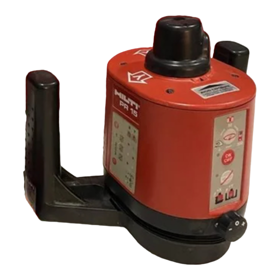
Page 7: Operating Controls And Indicators
1. Product information Operating controls and indicators Item Name Rotating head Laser exit apertures Baseplate with grip handles Servo button for X/Y incline Foot screw for vertical mode Control panel Brief instructions... -
Page 8: Control Panel
1. Product information Control panel Speed button (rotating head) Operation LED/ battery voltage ON/OFF button Incline LED Incline button (X/Y) X-incline LED Y-incline LED Servo button for X/Y incline Continued... - Page 9 1. Product information Control panel, continued ON/OFF button For switching the tool on and off. After the tool has been switched on, the laser beams start blinking. Operation / battery voltage LED green Tool is switched on flashing red Low battery voltage continuous red Battery discharged insert batteries )
- Page 10 1. Product information Control panel, continued Incline button For manual setting of the X and Y incline. Press the Incline button a first time: Align X incline using servo button X LED lights up red. Y LED lights up green. Y direction is levelled automatically.
-
Page 11: Quick-Start Instructions
1. Product information Quick-start instructions Horizontal mode Switch on using ON/OFF button . Operation LED lights up green. Alignment takes place automatically (within 30 s). X and Y LEDs on the control panel light up green. Axis (X/Y) green levelled inclined fixed Inclined plane mode... -
Page 12: Technical Data
1. Product information Technical data Measurement range 1 – 30 m [100 ft] (radius) with beam catcher 1 – 100 m [330 ft] with manual detector Accuracy ± 1.5 mm @ 10 m (horizontal and vertical modes) [± 0.06’’ @ 33 ft] Beam diameter <... - Page 13 1. Product information Technical data, continued Automatic cut-out If, when in the operating mode “levelled plane”, “vertical plane” or “inclined plane”, the tool is jolted ± 60 arc seconds [± 3 mm @ 10 m] out of levelling, - rotation stops - the laser flashes - LEDs flash alternately (Operation red, Incline orange) Power supply...
- Page 14 1. Product information Technical data, continued Dimensions 176 (L) x 242.5 (W) x 200.5 (H) mm [6.9 (L) x 9.5 (W) x 7.9 (H) inches]...
-
Page 15: Items Supplied
1. Product information Items supplied Item Number Name PR 15 rotating laser PA330/340 beam catcher Operating instructions Carrying case Batteries Cleaning cloth Desiccant... -
Page 16: Beam Catcher
1. Product information Beam catcher Item Name Marking notches Magnetic holder Reflective surfaces Hole for mounting on PA950/960 telescopic rod PA 330, scale in [cm] PA 340, scale in [cm, inches]... -
Page 17: Safety Instructions
Only then can the tool be operated safely. Laser classification The PR 15 rotating laser corresponds to laser safety class 2, based on the standards IEC825-1 / EN60825, and class II based on FDA 21 CFR. The eyelid closure reflex protects the eyes should anyone happen to look briefly into the laser beam. -
Page 18: Applications For Which The Tool Is Designed
- aligning equipment and elements in three axes. Electromagnetic compatibility (EMC) Although the Hilti PR 15 fulfils the strict requirements of the applicable directives, Hilti cannot completely exclude the following possibilities: - The PR 15 may cause interference which affects other equipment (e.g. -
Page 19: Usage And Handling
- Check the tool for possible damage before use. If the tool is damaged, have it repaired by a Hilti service centre. - If the tool has been dropped or subjected to other mechanical forces, its accuracy should be checked. - Page 20 - Although the tool is moisture resistant, it should be wiped dry before being put away in its carrying case. - The tool should be repaired only by Hilti service centres. Radiation in excess of class 2 may be emitted if the correct procedures are not observed when the casing is opened.
-
Page 21: Initial Operation And Usage
3. Initial operation and usage 3. Initial operation and usage Inserting the batteries Green flashing – low battery voltage LED: Steady red light, and laser off – battery discharged Inserting new batteries 1 Turn lever A from the LOCK position to OPEN. 2 Remove cover from battery compartment. -
Page 22: Horizontal Mode
(depending on the last operating mode selected). 3 Using the Speed button , select the operating mode and carry out the work. 4 After finishing the work, switch off the PR 15 using the ON/OFF button... -
Page 23: Vertical Mode
3. Initial operation and usage Vertical mode 1 Place the PR 15 rotating laser on a level surface and set it approximately horizontal using the foot screw on the baseplate. 2 Switch on the tool using the ON/OFF button Operation LED lights up green. -
Page 24: Inclined Plane Mode
X LED lights up red. Y LED off. 7 Using the Speed button , select the desired operating mode and carry out the work. 8 After finishing the work, switch off the PR 15 using the ON/OFF button If the work is interrupted If the Incline button... -
Page 25: Operation With The Beam Catcher (1-30 M)
3. Initial operation and usage Operation in conjunction with a beam catcher (1-30 m) PA 330 / PA 340 1 Set mode to 80 rpm using Speed button 2 Hold the beam catcher (PA 330 / 340) within the arc of the rotating laser beam. The laser beam follows the hand-held beam catcher, and oscillates within the range of ±... -
Page 26: Operation With The Manual Detector (1-100 M)
3. Initial operation and usage Operation in conjunction with a manual detector (1-100 m) PA 350 1 Set mode to 300 rpm using Speed button 2 Hold manual detector (PA350) in the rotating laser beam. The laser beam is indicated optically and acoustically. -
Page 27: Checks
Checking horizontal rotation Checking the horizontal alignment of the PR 15 1 Set up the tripod at the mid point between wall A and wall B. The distance between A and B should be approx. - Page 28 4. Checks Checking horizontal rotation, continued 7 Loosen tripod screw a little and carefully turn the tool through 180°, taking care not to displace the tripod. Fix the tool on again. 8 Switch on using ON/OFF button 9 Using the beam catcher, mark the height of the reference line on walls A and B, marks A2 and B2.
- Page 29 4. Checks Checking horizontal rotation, continued To check the other two directions, proceed in similar fashion: - Measure the first reference line in the position and then the second in the position Here too, the two markings must deviate by no more than 6 mm.
-
Page 30: Checking Vertical Rotation
4. Checks Checking vertical rotation Procedure 1 Set up tool and switch on. 2 Set mode to 0 rpm using Speed button 3 Turn rotating head manually and mark a point A on the wall near the floor. 4 Turn the rotating head upwards and mark point B. 5 Turn the tool around 180°, and set the laser beam to point A again. -
Page 31: Making Adjustments
4. Checks Making adjustments Adjusting the tool - Adjustment of the PR 15 rotating laser should be carried out only by trained and experienced personnel. - Accuracy cannot be guaranteed if the adjustment instructions are not followed precisely. - The tool must be adjusted in all three axes (X, Y, Z). - Page 32 4. Checks Making adjustments, continued Adjusting the X axis, continued 5 Mark the laser on the same wall as before (position X2). 6 Using the servo button , bring the laser precisely between the markings. 7 Press the Incline button .
- Page 33 4. Checks Making adjustments, continued Adjusting the Y axis, continued 3 Mark the laser in one direction (position Y1) 4 Turn the tool (not the tripod) through 180°. 5 Mark the laser on the same wall as before (position Y2). 6 Using the servo button , bring the laser precisely between the markings.
- Page 34 4. Checks Making adjustments, continued Adjusting the Z axis 1 Press and release the ON/OFF button Incline button simultaneously. Press and release the Incline button and the Speed button simultaneously within 3 seconds. The Incline LED flashes quickly, the Operation LED lights up..
- Page 35 After calibration, the accuracy of the tool should be checked once more. If the Operation LEDs flash red alternating with green and the orange Incline LED, please contact your local Hilti agent.
-
Page 36: Checking The Oblique Error
2 Set up the tool 1 to 2 metres in front of wall A and align it horizontally. 3 Mark the reference lines at points a’ and b’. The differential value between Db and Da must be ≤ 4 mm. In the event of deviations > 4 mm, please contact your local Hilti agent. -
Page 37: Accessories
5. Accessories 5. Accessories Manual detector At distances of greater than 30 metres and when lighting conditions are unfavourable, a manual detector should be used to detect the laser beam. The position of the laser beam is indicated optically and acoustically. Measuring rod The measuring rod can be pulled out telescopically, and is equipped with attachment points for the beam... - Page 38 5. Accessories 5. Accessories, continued Tripods Various tripods are available for setting up the PR 15 at the job site. Wall mounting bracket The wall mounting bracket makes it easy to mount the PR 15 on a wall.
-
Page 39: Fcc Statement (Valid In Usa)
6. FCC statement (applicable in U.S.) 6. FCC statement (applicable in U.S.) WARNING: This equipment has been tested and found to comply with the limits for a class B digital device, pursuant to part 15 of the FCC rules. These limits are designed to provide reasonable protection against harmful interference in a residential installation. - Page 40 6. FCC statement (applicable in U.S.) 6. FCC statement (applicable in U.S.), Continued WARNING: Changes or modifications not expressly approved by Hilti for compliance could void the user’s authority to operate the equipment. Label:...
-
Page 41: Eu Declaration Of Conformity
Positioning Systems 01/1999 01/1999 8. Warranty Hilti warrants that the tool supplied is free of defects in material and workmanship. This warranty is valid so long as the tool is operated and handled correctly, cleaned and serviced properly and in accordance... - Page 42 8. Warranty 8. Warranty, continued maintained. This means that only original Hilti consumables, components and spare parts may be used in the tool. This warranty provides the free-of-charge repair or replacement of defective parts only. Parts requiring repair or replacement as a result of normal wear and tear are not covered by this warranty.
- Page 43 Addresses Hilti Corporation FL - 9494 Schaan Principality of Liechtenstein Internet: www.hilti.com...
Need help?
Do you have a question about the PR 15 and is the answer not in the manual?
Questions and answers