Table of Contents
Advertisement
Advertisement
Table of Contents

Summary of Contents for Gravotech XCOM
- Page 1 OPERATING AND MAINTENANCE MANUAL X C O M CONTROL UNIT FOR MARKING MACHINES...
-
Page 2: Table Of Contents
Table of contents A. Foreword ..............................4 1. Appreciation ............................4 2. Information ............................4 B. Legal notices ............................5 C. Regulation observance ...........................6 D. Description of symbols used .........................7 1. Shared labels ............................7 2. Required safety labels ........................... 7 E. Introduction .............................8 1. - Page 3 4. Installation ............................16 „ Switching on the machine ........................16 „ Power down ............................17 „ Restarting ............................17 K. Using the machine ..........................18 1. Using the T08 program ........................18 L. Communication .............................19 1. RS232 cable ............................19 2.
-
Page 4: Foreword
A. Foreword 1. Appreciation Thank you for choosing XCOM - Gravotech. Gravotech is pleased to count you among the users of its engraving and traceability solutions. For help, contact Gravotech. For more information on products, visit www.gravotech.com website. 2. Information To ensure security and productivity, read this manual before starting-up the equipment. -
Page 5: Legal Notices
User. Gravotech shall not be liable for any damages, that the User or its property, a third party or the Product itself may suffer, caused by the Product and arising from any inappropriate use or misuse of the Product, negligence, carelessness, inadequate supervision or maintenance, failure to observe the safety or usage instructions described herein or otherwise communicated to the User, the use of poor- quality or non-recommended lubricants, fluids and additives or where there is fault on the part of the User or a third party. As provided in... -
Page 6: Regulation Observance
XF530p, XF530m, XM500 Dot peen marking: Partly completed machinery XF510Cp-Sp-Dp, XF510Cm-Sm-Dm, XE310Cp-Sp Scribing marking: Partly completed machinery XF510Cr-Sr-Dr, SV510 CCU, Rack, TouchPad UC500, UC500 SV, UC Laser, XCOM Racks IS Laser fume extractor: ES10, ES30, ES50, ES Mini LE120HP, LE140HP, LE150HP, LE190HP, LNI900 Accessory: Partly completed machinery Rotary APF, Laser APF, Dotpeen APF... -
Page 7: Description Of Symbols Used
D. Description of symbols used Last updated: 06/2020 1. Shared labels Refer to instructions manual/booklet. Fuse Alternating current Direct current The equipment must be disposed of at an appropriate collection point for processing, sorting, and recycling of Waste Electronic and Electrical Equipment (WEEE). European conformity By following these instructions, you are helping the environment, contributing to the preservation of our natural... -
Page 8: Introduction
The Control Unit is designed to manage the markings performed by the numerically controlled Heads manufactured by Gravotech. It contains the control and power electronics, as well as a screen. The Control Unit is the centre of the traceability system. -
Page 9: Unpacking
F. Unpacking Depending on the order, the Control Unit is packed on its own or with a machine. In order to protect the machine from humidity and dust, keep the machine in its original packaging in case of prolonged storage. 1. Unpacking - Package contents The packaging and its contents may vary according to the marking head. See the user manual of the machine. M_XCOM_EN_B... -
Page 10: Safety
„ Personnel safety Turn off the machine before beginning any cleaning, maintenance or repair procedure. • The XCOM machine is designed for marking applications. If used for other purposes, Gravotech cannot guarantee the quality of the result. Gravotech is not responsible for damage caused by inappropriate use of the machine. • Do not use this marking equipment in an explosive environment. • Use the appropriate protection when equipment is used in a polluted environment. Use of these protections are the user's or the integrator's responsibility. -
Page 11: Description Of The Control Unit
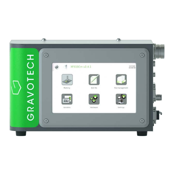
H. Description of the Control Unit 1. Front view of the machine Color touch screen Connectors (See: View of connectors) 2. Rear view of the machine Hook(s) (DIN) M_XCOM_EN_B... -
Page 12: Installation
I. Installation 1. Physical installation Position the Control Unit horizontally, in a dry, ventilated area, at least 20 cm (7.874 in) from the floor. Allow clearance (connections and cables): right side of the machine Mounting hooks for DIN rail are located at the back. Do not obstruct air circulation under the machine. Respect the clearance areas indicated on the drawing. Clearance dimension Front panel: 19" 5U Clearance dimension M_XCOM_EN_B... -
Page 13: Electrical Installation
Connection of shielding: the communication cables (All Or Nothing I/O or Ethernet - RS232 computer cables) must be shielded with both ends of the shielding connected to the equipment ground via the shortest possible link. • Grounding: connect together all the conductive metal grounds (no paint or treatment such as anodization) of the equipment (frame, cabinet, marking machine) to ensure effective connection. Where possible, there should be multiple connection points to improve the connection quality. • Use the Gravotech accessories. M_XCOM_EN_B... -
Page 14: Connections - Installation
J. Connections - Installation 1. View of connectors : Ethernet connection (RJ45) : USB Host connector (x2) : USB Device connector: Machine / PC connection (not available) RS232: RS232 management connection (Sub-D9M) DEDICATED I/O: Dedicated Inputs/Outputs (Sub-D9F) Power connector Fuse carrier On / Off switch ID plate 10. SAFETY: emergency stop (optional): M12 (male) - 12 channels 11. USER I/O: Generic Inputs/Outputs (Sub-D25F) 12. Safety label 13. OPTION: connection(s) for accessory(ies): Rotary Device (cylinder attachment): Sub-D26F - High density 14. Z AXIS: Z axis (Sub-D15F) 15. MARKING HEAD: head/CCU connecting cable 16. FIELDBUS: fieldbus (optional) M_XCOM_EN_B... -
Page 15: Connections
Connections - Installation 2. Connections The different elements of the equipment must be connected with the power off. The power supply should be connected last. To use the CCU, 3 connections must be performed, in the following order (minimum): • Wiring of the "Stop marking" contact: SubD 9 connector (female) - with jumpers • Marking head • Power supply „ Wiring of the "Stop marking" contact The machine comes delivered with a SubD 9 point connector with bridge so that it can be used immediately. It must be connected to the dedicated Inputs/Outputs connector located on the right side of the CCU. -
Page 16: Hook(S) (Din): Installation Location(S)
Connections - Installation 3. Hook(s) (DIN): Installation location(s) Units: mm 4. Installation „ Switching on the machine 1. Place the switch in the "I" position (On). A presentation screen will appear for a few seconds, followed by the main menu screen. Leave the machine powered on, even if it is only going to be used at intervals. If the machine does not switch on: •... -
Page 17: X84; Power Down
Connections - Installation „ Power down 1. Set the general stop button to the "O"(Stop) position. Switch off the machine in the following situations: • when the operator is permanently leaving the machine • in the event of physical damage (something is dropped on the machine, fire, a liquid is spilled on the machine, etc.) •... -
Page 18: Using The Machine
K. Using the machine 1. Using the T08 program The home page is composed of 6 menus, each represented by an icon. Return to previous screen Icon used to return to the main menu, followed by the name of the menu. This icon appears several times in the program. -
Page 19: Communication
L. Communication The Control Unit can be used in various modes: • Human mode: can be used by a human user, who interacts via the Man-Machine Interface with no need for any other external device. Description of the human-machine interface: color touch screen and/or Dedicated Inputs/Outputs, Barcode reader, 2D-code reader. -
Page 20: Dedicated Inputs/Outputs
Communication 2. Dedicated Inputs/Outputs Wiring of the female 9 SubD connector This connector allows to communicate with the machine. It contains dedicated All-or-Nothing Inputs and Outputs. They are used in the marking cycle (accessory connection (button box for start / stop cycle or start cycle foot pedal...)). Use exclusively shielded cable. Connect the shielding to the electrical ground on either side of the cable. Pin functions Number Description... - Page 21 Communication Connection diagram for the dedicated Inputs / Outputs SubD 9F Communication Machine CCU side Start marking External contact Stop marking External contact Marking in progress External light Marking in progress Fault External light Machine ready External light Common Relay M_XCOM_EN_B...
-
Page 22: X84; Description Of The Communication Signals
Communication Note In the diagram above, the Inputs are wired to the internal power supply, available on the connector of the CCU (+ 24 V DC). The "Marking in progress", "Machine ready" and "Fault" Outputs are wired to an external power supply. „ Description of the communication signals • Start marking (Input) - To activate the "Start marking" Input, establish a zero potential electrical connection between pins 4 and - This connection must not be inferior to 500 ms nor superior to the cycle time of the marking file. • Stop marking (Input) - To activate the "Stop marking" function, open the electrical connection between pins 5 and 9. - This input does not guarantee immediate stoppage. -
Page 23: X84; Timing Diagrams Of The Communication Signals
Communication • Fault (Output dry contact) - The information "Fault" is available between pins 2 and 7. It is provided by a potential free "dry" contact (relay contact). - This signal indicates that the CCU has a fault (either of power, or of CPU). Characteristics Maximum voltage 24 V DC Maximum intensity 250 mA Status Fault Closed contact „... - Page 24 Communication • In-process mode: Impulse Start cycle nd o marking cycle Information Marking in progress Marking ready oaded This mode is selected by default. M_XCOM_EN_B...
- Page 25 Communication • Maintained mode: Impulse Start cycle nd o marking cycle Information Marking in progress Marking ready oaded M_XCOM_EN_B...
- Page 26 Communication • Pulse mode: Use only recommended with earlier-generation machines. Impulse Start cycle nd o marking cycle Information Marking in progress Marking ready oaded M_XCOM_EN_B...
-
Page 27: Generic Inputs/Outputs
Communication 3. Generic Inputs/Outputs „ Wiring of the female 25 SubD connector This connector allows the connection of generic Inputs/Outputs. Use exclusively shielded cable. Connect the shielding to the electrical ground on either side of the cable. Pin functions Number Description + 24 V - 300 mA max (common to all outputs) Input I0... -
Page 28: X84; Characteristics Of The Inputs
Communication Not connected Not connected „ Characteristics of the Inputs 8 non-insulated inputs are available and can be operated in positive logic. It is possible to control the Inputs with the + 24 V internal voltage available on pins 1 and 14, and referenced Gnd on pins 6-7-10-19-20-23. - Page 29 Communication • Wiring of 8 inputs with power supplied by XCOM Internal connections: + 24 V DC power supply (1-14) - Gnd (6-7-10-19-20-23) • Wiring of 8 inputs with power supplied by the user External power supply (+ 24 V DC) External power supply (+ 24 V DC) Internal connections: + 24 V DC power supply (1-14) - Gnd (6-7-10-19-20-23) M_XCOM_EN_B...
-
Page 30: X84; Characteristics Of The Outputs
Communication „ Characteristics of the Outputs 4 Outputs of the type NPN with open collector are available. The maximum external power supply for the Outputs is 24 volts (continuous current). The maximum current that can be commutated by an Output is 40 mA. The Outputs are not protected against polarity inversion and over current. When connecting inductive charges use an anti-parasite protection and a freewheeling diode to avoid damaging the Outputs. -
Page 31: Usb Host Connector
Communication 4. USB Host connector - This connector allows to connect a USB key for: • saving or loading files • updating the internal program T08 Remarks • The key must be formatted in FAT32. • The external hard drives cannot be used. Never remove the key during a transfer between the CCU and the key. Doing so may destroy the files or the key. -
Page 32: Fieldbus Connector (Optional)
Communication 6. FIELDBUS connector (optional) Depending on the type of fieldbus chosen as an option, there may be 1-2 connector(s), of variable type (RJ45, M12,...). The connectors and signals conform to the type of fieldbus chosen. 7. SAFETY connector (optional) This circular screw connector M12 has 12 contact(s). 4 of the contacts can be used for a 2-channels safety chain. Enables the achievement of a safety level PL d (EN ISO 13849-1: Performance Level d). The others are reserved for a different use. Do not use. „ connector Male connector M12 on panel installation Pin(s) Description Signals... - Page 33 Communication • Examples Install the wiring as shown. M_XCOM_EN_B...
-
Page 34: Accessories Available Upon Request
66817 Power cable 2 m (6.562 ft): China Head/CCU connecting cable - standard version Ref. 52845 3 m (9.842 ft) Head/CCU connecting cable 52846 6 m (19.685 ft) Head/CCU connecting cable 52847 10 m (32.808 ft) Head/CCU connecting cable 52848 15 m (49.212 ft) Head/CCU connecting cable Head/CCU connecting cable - robotic version Ref. XCOM p XCOM m 52853 67526 3 m (9.842 ft) Head/CCU connecting cable 52854 67527 6 m (19.685 ft) Head/CCU connecting cable 52855 67528 10 m (32.808 ft) Head/CCU connecting cable 52856 67529 15 m (49.212 ft) Head/CCU connecting cable Ref. - Page 35 Used to integrate the CCU in a cabinet. Gravotrace standard marking program Developed in a Windows environment, this program combines all the capabilities and user-friendliness of a PC. Contact Gravotech. 52717 Button box for start / stop cycle The green button is used to launch marking (same function as the foot pedal).
-
Page 36: Preventive Maintenance
N. Preventive maintenance Turn off the CCU before any intervention. 1. Changing the fuse (fuse carrier) A damaged fuse is the result of a problem on the machine or its environment. Changing the fuse does not solve this problem. 1. Unplug the power supply cord. 2. Extract the fuse holder with 2 screwdrivers. 3. -
Page 37: Incidents And Resolution Of The Problems
O. Incidents and resolution of the problems Description Things to check Action The screen on the front panel of the Is the power supply switched on? See: Power supply connection CCU does not light up. Is the cable properly connected? See: Changing the fuse e On/Off switch in the On position? -
Page 38: Dimensional Drawings
P. Dimensional drawings 1. Dimensional drawing of the Control Unit in box configuration Units: mm M_XCOM_EN_B... -
Page 39: Dimensional Drawing Of The Control Unit In Rack Configuration
Dimensional drawings 2. Dimensional drawing of the Control Unit in rack configuration Adapter plate (front panel) USB Host connector View from above Units: mm M_XCOM_EN_B... -
Page 40: X84; Ccu Assembly In Rack Configuration
Dimensional drawings „ CCU assembly in rack configuration To perform the assembly, imperatively use the mounting kit provided. See the manual delivered with this option. Check that the assembly is secure. M_XCOM_EN_B... - Page 41 Dimensional drawings M_XCOM_EN_B...
- Page 42 Dimensional drawings M_XCOM_EN_B...
-
Page 43: Technical Specifications
Q. Technical specifications 1. Physical characteristics Pneumatic version - Electromagnetic version Scribing version Dimensions (L x w x h): machine 287 mm (11.299 in) x 144 mm (5.669 in) x 170 mm (6.693 in) Net weight: machine 2.7 kg (5.952 lb) 3.1 kg (6.834 lb) 2. Environment Operating temperature 5 °C (41 °F) - 45 °C (113 °F) Storage temperature 0 °C (32 °F) - 50 °C (122 °F) Humidity level 0 - 80% 3. Electrical characteristics Pneumatic version - Electromagnetic version Scribing version Nominal voltage 100-240 V AC Frequency 50-60 Hz...
Need help?
Do you have a question about the XCOM and is the answer not in the manual?
Questions and answers