Table of Contents
Advertisement
Quick Links
Advertisement
Table of Contents
Troubleshooting

Subscribe to Our Youtube Channel
Related Manuals for Dexter Laundry T-750 C4


Summary of Contents for Dexter Laundry T-750 C4
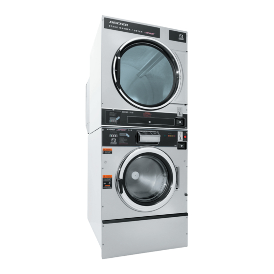
- Page 2 Dexter Commercial Vended Stack Washer Dryer T-750 C4 Parts & Service Manual Starting serial number 8533-120-001 9/21...
- Page 3 Equipment Safety Warnings Symbols and Terminology Used in this Equipment Indicates an imminently hazardous situation, which if not avoided, will result in death or serious injury. Indicates a potentially hazardous situation, which if not avoided could result in death or serious injury. Indicates a potentially hazardous situation which, if not avoided, may result in minor or moderate injury.
- Page 4 Equipment Safety Warnings Symbols and Terminology Used in this Equipment Warning! Do not operate equipment if door glass is damaged in any way. Warning! Keep clear of rotating parts. Prohibited! Do not enter this equipment or space. Prohibited! Do not step or stand on this equipment. Prohibited! Do not operate without all guards and covers in place.
- Page 5 Indicates an imminently hazardous situation, which if not avoided, will result in death or seri- ous injury. Indicates a potentially hazardous situation, which if not avoided could result in death or serious injury. Indicates a potentially hazardous situation which, if not avoided, may result in minor or moderate injury.
- Page 6 WARNING •All washers must be installed in accordance to all applicable electrical, plumbing and all other local codes. •These installation and operation instructions are for use by qualified personnel only. To avoid injury and electrical shock, do not perform any servicing other than that contained in the installation and operation instructions, unless qualified.
- Page 7 WARNING Children should be supervised to ensure they do not operate or play in or around equipment. Keep all panels in place to protect against electrical shock and injury and add rigidity to washer. This appliance is not intended for use by persons (including children) with reduced physical, sensory or mental capabilities, or lack of experience and knowledge, unless they have been given supervision or instruction concerning use of the appliance by a...
- Page 8 Warning! Do not operate equipment if door glass is damaged in any way. Warning! Keep clear of rotating parts. Prohibited! Do not enter this equipment or space. Prohibited! Do not step or stand on this equip- ment. Prohibited! Do not operate without all guards and covers in place.
- Page 9 Prohibited! Do not attempt to open, touch, or pro- ceed before referring to the manual or unless quali- fied. Mandatory! Read all supporting documentation be- fore operating or maintaining equipment. Mandatory! Disconnect power before servicing equipment. Mandatory! Lock out and tag out before servicing this equipment.
-
Page 10: Table Of Contents
Dexter Safety Table of Contents Guidelines Section 1: Specifications, Mounting Dimensions Specifications..........12-15 WARNING Dimensions............16-17 Section 2: Installation & Operating Instructions These washers are equipped with devices and Washer Installation ........20 features relating to their safe operation. To avoid injury or electrical shock, do not perform Electrical Connections &... - Page 11 Section 8: Front Panel Removal ........122 Back Panel Removal ........122 Washer Electrical & Wiring Schematics Drain Valve Access ........122 Start Circuit ..........150 Drain Valve Cleaning ........122 Fill Circuit ..........150-151 Detergent Dispenser ........124 Wash Circuit ..........151 Vacuum Breaker/Air Gap ....... 124 Drain, Rinse 1, 2 &...
- Page 12 Section 1: Washer and Dryer Specifications and Mounting Part # 8533-120-001 9/21...
- Page 13 Stacked Washer Dryer Models Electrical Spec: Circuit Breaker / Stacked Model Washer \ Dryer Running Amps / Wire Size/ Option Designation Model # SC0750NE-16EC4R- DCS050ND-11EC2R- 208-240/60/1, Single 2 Wire + Ground, United SWBCG-USA States Quarter Optical Acceptor SWBCG-USA WCS750XC-12EC4X- 208-240/60/1or3, Single 2 Wire + Ground, 3 SWBCS-USA Phase 3 Wire + Ground, United States Quarter 9999-746-001...
- Page 14 Stacked Washer Dryer Models Electrical Spec: Circuit Breaker / Stacked Model Washer \ Dryer Running Amps / Wire Size/ Option Designation Model # SC0750NE-39AC4R- DCS050ND-39AC2R- 230/50/1, Single 2 Wire + Ground, No Acceptor SWKCG-VRX SWKCG-VRX WCS750XC-39XC4X- 230/50/1, Single 2 Wire + Ground, No Acceptor SWKCS-VRX 9999-746-011 SC0750NE-39AC4R-...
-
Page 15: Specifications
Washer Specifications: Dry Weight Capacity 50lbs (22.7 kg) Cylinder Diameter 30” (76.2 cm) Cylinder Depth 16” (40.6 cm) Cylinder Volume 6.5 cu ft. (184.1 L) Floor to Door Bottom 16” (40.6 cm) Door Opening 19.25” (48.9 cm) Speeds G-Force (RPM) High Extract Speed 200 G 685 RPM... - Page 16 Dryer Specifications: Dry Weight Capacity 50 lbs. (22.7 kg) Cylinder Diameter 32 1/2” (82.5 cm) Cylinder Depth 33” (83.8 cm) Cylinder Volume 15.8 cu ft (447.4 L) Floor to Door Bottom 55 1/8” (140.0 cm) Door Opening 25 5/8” (65.1 cm) Energy Data Gas Models 60Hz - 108,000 BTU/hr...
-
Page 17: Dimensions
Machine Dimensions: Part # 8533-120-001 9/21... - Page 18 SWD Mounting Pad Dimensions CONCRETE PEDESTAL MOUNTING FLOOR OUTLINE Figure 1-1 Figure 1-2 Part # 8533-120-001 9/21...
- Page 19 Notes Part # 8533-120-001 9/21...
- Page 20 Section 2: Washer and Dryer Installation & Operating Instructions Part # 8533-120-001 9/21...
-
Page 21: Washer Installation
Washer Installation All washers must be installed in accordance with all local, state, and national building, electrical, and plumbing codes in effect in the area. Foundation Requirements The washer must be securely bolted to a substantial concrete floor or mounted upon a suitable base which is securely bolted and machine grouted to a substantial concrete floor. - Page 22 To Make Electrical Connections Disconnect all power to the washer. Remove screw and lift out the cover located in the upper left corner of the machine (as viewed from the back). • If power is 208-240-3PH-60Hz, connect L1, L2, L3, and ground. If there is a high leg it must be connected to L3.
-
Page 23: Dryer Installation
Dryer Installation All commercial dryer installations must conform with local applicable local codes or in the absence of lo- cal codes, with the National Fuel Gas Code ANSI Z223.1A-1988. Canadian installations must comply with current standard CAN/CGA-B149(.1 or .2) Installation Code for Gas Burning Appliances or Equipment, and local codes if applicable. - Page 24 NOTE: The following considerations must be observed for gas dryer installations where dry cleaners are installed. The sources of all makeup air and room ventilation air move- ment to all dryers must be located away from any dry cleaners. This is necessary so that solvent vapors will not be drawn into the dryer inlet ducts.
- Page 25 recommended that no more than 20 feet of straight 8” diameter pipe with two right angle elbows be used. When more than two elbows are used, two feet of straight pipe should be removed for each additional elbow. If the exhaust pipe passes through a wall, a metal sleeve of slightly larger diameter should be set in the wall and the exhaust pipe passed through this sleeve.
-
Page 26: Washer Operating Instructions
Washer Operating Instructions Washer Emergency Stop / Safety Door Lock This machine is equipped with a Safety Door Lock that locks the door closed from when the cycle is started until the cycle is complete. The door lock prevents opening the door for up to 3 minutes if the power is interrupted during the cycle. -
Page 27: Dryer Operating Instructions
At the correct time in the wash bath cycle the “ADD BLEACH” Detergent will come on indicating the time and showing a diagram of the location for adding bleach if desired. The timing is 2 1/2 Measurements minutes after start of wash bath the light will come on and stay on for 2 1/2 minutes or end of wash bath . - Page 28 TRANSIENT VOLTAGE SURGE SUPPRESSORS Like most electrical equipment your new machine can be damaged or have its life shortened by voltage surges due to lightning strikes which are not covered by factory warranty. Local power distribution problems also can be detrimental to the life of electrical components. We recommend the installation of transient voltage surge suppressors for your new equipment.
- Page 29 Notes Part # 8533-120-001 9/21...
-
Page 30: Washer And Dryer Programming Instructions
Section 3: Washer and Dryer Programming Instructions Part # 8533-120-001 9/21... - Page 31 PROGRAMMING INSTRUCTIONS: The washer control can be programmed to prompt the user for alternate vend prices, change washer cycle times, temperatures and many other options. This can be accomplished in two ways: 1. Manual programming utilizing the “START”, “HOT”, “WARM” and “COLD” buttons 2.
- Page 32 Programing Selection: These alternate functions allow the user to move through a menu of options to choose various program- mable settings. Figure 2, shown below, shows the top level menu. Choosing an option from the top level menu will then display the next level of options (the sub menu). Figure 2 OPTIONAL_CYCLES ERROR_CODES...
-
Page 33: Rapid Advance Mode
Optional Cycles Option: This option allows the user to select the different test and short-cycle options. Figure 3 QUICK_TEST OPTIONAL_ RAPID_ADVANCE CYCLES FINAL_RINSE_ AND_SPIN Quick Test Option: When the Quick Test Option is chosen, the washer will begin a shortened wash cycle without the displayed vend price being met. - Page 34 Final Rinse and Spin Option: “Final Rinse and Spin” will begin only the Final Rinse Bath and Final Spin portions of the cycle without the displayed vend price being met. The configured temperature, cycle times, and spin speed for the Final Rinse Bath and Final Spin settings will be used when this option is selected.
- Page 35 Prices Option: This option allows the user to set values for coin acceptor inputs and to set the vend price. It also allows the user to return the values to factory defaults. “RIGHT COIN” and “LEFT COIN” are the two possible inputs from coin acceptors.
- Page 36 Temp Pricing Option: The Temperature Pricing option allows for the user to prompt the customer for varying vend prices based on the water temperature the customer selects. If a value other then 0 is programmed for either the “WARM ADDER” or “HOT ADDER”, the feature becomes active. The programmed value is added to the base vend price when that particular water temperature is chosen.
- Page 37 Cycles Option: This option allows the user to set the bath time and spin time for the “Wash” bath. It also allows the user to set bath time, water temperature, and spin time for “Rinse” and “Final rinse” baths. (Water temperature for the “Wash”...
- Page 38 Final Spin: The washer “Final Spin” is the spin that occurs after all selected baths & intermediate spins have been completed. It is a higher spin speed then previously occurring intermediate spins. The benefit of this higher spin speed is that more water is extracted from the wash load, which minimizes the drying time needed. However, in some cases, if the Dexter installation guidelines are not followed properly, it may be necessary to reduce the spin speed of the “Final Spin”.
- Page 39 Plus Cycle Options: The Plus Cycle options allow for the user to prompt the customer for varying vend prices based on addi- tional wash baths chosen. In general, the user can program the additional wash baths in a similar manner to what was described in the “Cycles”...
- Page 40 Pre-Wash: If the user programs a “CYCLE TIME” for Pre-Wash other then 0 (“NO CYCLE”), the feature becomes active. However, the customer will not be prompted to pay an additional vend price for Pre-Wash unless the user programs the Price to a value other then 0 (“FREE”). With the Pre-Wash feature active, an additional bath and, optionally, an additional spin, will occur before the standard Wash bath described in the Cycles Options section.
- Page 41 Settings Options: The Settings options allow for the user to make various programming changes to change how the control operation affects the customer. See below for detailed information on each next level option. It also allows the user to return the programmable values to the factory default setting. To reset all values in the Settings options to factory default, press “ENTER”...
- Page 42 Sounds: If the user programs the Sounds to “OFF”, the control will not sound the enunciator at the end of a wash cycle. The factory default is “ON”. Password: If the user programs the Password to any value other then ‘0000”, the control will prompt the user to enter a password (the programmed value) before manual programming can be accessed.
- Page 43 Date: The control uses a Real Time Clock (RTC) to internally track the time and date. The RTC continues opera- tion even if the control loses external power. The RTC is set for the current date. However, if a problem occurs and the RTC date is not accurate, it can be reset to the current date using this option.
- Page 44 Coin Audit: The coin audit field shows the accumulation of coin pulses that were sent to the control over each of the left and right coin inputs. Note that this is a count of coin pulses, not an accumulated report of vend value. The user can also return the coin audit amounts to the factory default setting (zero).
- Page 45 Control Menu: The Control menu allows for the user to observe important technical information for the control and Vari- able Frequency Drive system. No changes can be made at this menu. See below for detailed information on each sub menu. Figure 11, shown below, shows the sub menu options for Control: SERIAL_NUMBER XXXXXXX...
- Page 46 USB Menu: The USB menu allows for the user to move programming files back and forth from a common USB memory stick. Figure 12, shown below, shows the sub menu options for Control: INSTALL_USER_FILE_FROM_USB CONFIRM_PRESS_START COPY_USER_FILE_TO_USB COPY_PRESS_START USB MENU INSTLL_FIRMWARE_FROM_USB INSTALL_FIRMWARE_PRESS_START PROGRAM_MENU Part # 8533-120-001 9/21...
-
Page 47: Dryer Programming
PROGRAMMING THE DRYER CONTROL The dryer control can be programmed to prompt the user for alternate vend prices, change dryer cycle times, temperatures and many other options. This can be accomplished in two ways: 1. Manual programming utilizing the “Start”, “High”, “Medium” and “Low” buttons for the bottom dryer. - Page 48 When manual programming mode is entered, the “START”, “HIGH”, “MEDIUM” and “LOW” buttons perform alternate functions. Button Name Alternate Function in Programming Mode Start Becomes the action to accept the displayed option or the “Enter” key Becomes the action to move UP through displayed options (Press & hold for accelerated scrolling) Warm Becomes the action to move DOWN through displayed options (Press &...
- Page 49 These alternate functions allow the user to move through a menu of options to choose various program- mable settings. The figure below shows the top level menu. Choosing an option from the top level menu will then display the next level of options (the sub menu). QUICK_TEST CONTINUOUS_TEST ERROR_CODES...
- Page 50 Continuous Test Option: Similar to the Quick Test, when the Continuous Test Option is chosen, the dryer will begin a dry cycle with- out the displayed vend price being met. However, in this case, it will be a continuously-running cycle. It will not time out after any designated amount of time.
- Page 51 Prices Option: This option allows the user to set values for coin acceptor inputs, vend price & time and extend dry price & time. It also allows the user to return the values to factory defaults. After changing prices using the “UP” or “DOWN”...
- Page 52 The figure below shows the sub menu options for Prices: 00.01-99.99 RIGHT_COIN (00.01 increments) 00.01-99.99 COIN_VALUE LEFT_COIN (00.01 increments) DEFAULT RESET PRICES FREE - 00.01-99.99 PRICE_SET_VEND (00.01 increments) 00:30-99:30 TIME_SET_VEND (00:30 increments) VEND_PRICE 00:30-99:30 FREE_SET_TIME (00:30 increments) DEFAULT RESET 00.01-99.99 PRICE_SET_EXTEND (00.01 increments) 00:30-99:30...
- Page 53 Cycles Option: This option allows the user to set temperature and cooldown information for the drying cycle. It also al- lows the user to return the values to factory defaults. 1. “TEMP SETTINGS” allows the user to make adjustments, within a designated range, to the cycling temperature for each of the “LOW”, “MEDIUM”...
- Page 54 NO HEAT – 110-150 F (increments of 5) NO HEAT – 39-63 C (increments of 3) 120-170 F (increments of 5) MEDIUM 45-75 C (increments of 3) TEMP_SETTINGS 150-190 F (increments of 5) HIGH 63-87 C (increments of 3) DEFAULT RESET 00:00-10:00 (00:30 increments)
- Page 55 Temperature Pricing Option: This option allows the user to require additional vend amounts be added based on the drying temperature chosen by the customer. This pricing adder is effective only for the Base Vend Price (it does not affect the Extend Dry Price).
- Page 56 Settings Options: The Settings options allow for the user to make various programming changes to change how the control operation affects the customer. See below for detailed information on each next level option. 1. “DECIMAL POINT”: If the user programs the Decimal Point to “OFF”, control display will not show a decimal point on any vend price values.
- Page 57 8. “SHIFT HOURS”: This feature allows the user to shift the time used by the control from the time kept internally by the control. The control uses a Real Time Clock (RTC) to internally track the time and date. The RTC continues operation even if the control loses external power. The RTC is set for Central Standard Time and no daylight savings.
- Page 58 The figure below shows the sub menu options for Settings: DECIMAL_POINT DISPLAY_TIME MIN+SEC TEMP_SCALE SOUNDS 0000-9999 PASSWORD (0000=OFF) ENGLISH SETTINGS SPANISH LANGUAGE FRENCH MALAY ITALIAN SHIFT_HOURS -23:59 – 23:59 TIME 00:00 DATE 00.00.00 OUT_OF_SERVICE Part # 8533-120-001 9/21...
- Page 59 Usage Menu: The Usage menu allows for the user to track data about machine usage. See below for detailed information on each sub menu option. 1. “COIN AUDIT”: The coin audit field shows the accumulation of coin pulses that were sent to the control over each of the left and right coin inputs.
- Page 60 Control Menu: The Control menu allows for the user to observe important technical information for the control. No chang- es can be made at this menu. See below for detailed information on each sub menu. 1. “SERIAL NUMBER”: This is the control serial number. 2.
- Page 61 REVERSING OPTIONS The dryer can be set to reverse at different intervals dependent on owner’s preference. The style of operation is determined by the location of the BROWN jumper wire located in the rear control box, on the frequency drive. (See image for jumper location) ...
- Page 62 Part # 8533-120-001 9/21...
- Page 63 Part # 8533-120-001 9/21...
-
Page 64: Dryer Service,Troubleshooting And Schematics
Section 4: Dryer Service, Trouble Shooting and Schematics Part # 8533-120-001 9/21... - Page 65 Service Procedures Clothes Door Removal 1. The clothes door may be removed from the hinge bracket by unscrewing and removing the allen- head pivot screw located at the door upper hinge point. 2. Next lean the door out of the top of the hinge bracket and lift the door from the bottom hinge pin.
- Page 66 B. Manual Reset Over temperature Safety Thermostat- The second hi-limit thermostat is located on the right side of the burner housing as you view from the back of the machine. It is just above the gas valve and covered by a guard with a small access hole. 1.
- Page 67 Temperature Testing To check the temperature in the dryer tumbler, press and hold the start button and while holding the start button also press the temperature button for the temperature to be checked. The display will read out the current temperature. 50Lb Stack Washer/Dryer Temperature Sensor Removal First remove Electronic Control.
- Page 68 Inverter Drive Motor removal 1.) Remove power from the machine by turning off the circuit breaker. 2.) Remove Rear Control box cover by removing the two 5/16 screw. 3.) Remove rear belt guards. 4.) Disconnect Motor wires; T1, T2, and T3 from the inverter drive, and the ground screw from the control box.
- Page 69 1. On the set screws and torque to 165 in/lbs. 2. The Motor is mounted with 4 bolts to the motor mounting bracket on the rear of the dryer. 3. Reassemble in reverse order. Air Flow Switch Operation And Adjustment The air flow switch assembly is part of the ignition safety circuit and insures that the burners don’t operate unless there is air flow.
- Page 70 Ignition System-Function & Sequence During normal dryer operation, the following occurs: 1. The dryer electronic control calls for heat. 2. If the drive motor is running, the blower motor safety circuit provides power to the electronic control. If the control senses that the heat should be on, a circuit is closed allowing power through the high limit thermostat, air flow switch.
- Page 71 Main Burner Orifice Removal 1. Remove manifold and gas valve assembly as above. 2. Using an open end wrench, remove orifices from manifold. Main Burner Removal Remove the 4 screws securing the cover for the burner housing and the one screw mounting the high limit cover.
- Page 72 Notes Part # 8533-120-001 9/21...
- Page 73 Trouble Shooting Dryer Electronic Control Diagnostic Lights The electronic control has 3 diagnostic lights to aid in service of the dryer. The Dryer has indicator lights for the motor circuit, door switch circuit, and the heat circuit. When the electronic control is carefully unlocked and moved forward these lights are visible on the circuit board.
- Page 74 Light Model Selection Jumper Motor Light Program Switch Door Closed Light Figure: 1 Part # 8533-120-001 9/21...
- Page 75 To enter a test Cycle Mode you will have to enter the programing mode: MANUAL PROGRAMMING: The dryer must be in idle mode for the manual programming menu to be accessed. Idle mode is when the dryer is not actively running a drying cycle and the vend price is displayed on the screen. To enter the manual programming mode, the control tray on the dryer must be unlocked and pulled out to reveal the programming button.
- Page 76 Error Codes Symptom Probable Cause Suggested Remedy PCB ERROR2 Analog / Digital Error Power machine down and try to reset control. Verify voltage to the control board. Check ground to board. Replace control board if error can not be cleared COMM ERROR1 Communication Bus Power machine down and try to reset...
- Page 77 TROUBLESHOOTING Suggested Symptom Probable Cause Remedy Tumbler does not turn Drive Belts Check both drive belts. Replace if failed. Drive Motor Check capacitor and motor. Replace if failed Door Switch Check for door closed L.E.D on control board. Check door switch contacts and adjustment.
- Page 78 Probable Symptom Suggested Remedy Cause Tumbler turns Glass Fuse Check small glass control fuse in back of dryer. but no spark Replace if failed. at burner Temperature The temperature sensor should have between Sensor 40,000 ohms resistance at room temperature if okay.
- Page 79 DCS050 Reversing 60Hz. Wiring Schematic Dryer Idle - No Coins Added: 208/240 VAC 60 Hz power is supplied to the main power terminal block and comes out on BLK/RED and BLK/BLU wire. 208/240 VAC now passes to the motor control relay (R1) and also passes to the multi-tap control step-down transformer.
- Page 80 Heat Circuit With the blower motor running, 24 VAC provided through the centrifugal switch on the red wire and con- necting to the violet wire to the computer board gas relay. The temperature sensing probe is found under each tumbler in the lint tray area and sends resistance values back to the computer board for temperature sensing.
- Page 81 End of Cycle At the end of the cool down, the computer board opens the upper run relay, which removes power from the blower motor control relay (R1) and also removes power to the (R2) drive enable relay which deacti- vates the variable frequency drive and motor.
- Page 82 Notes Part # 8533-120-001 9/21...
- Page 83 Wiring Schematic Dryer Part # 8533-120-001 9/21...
- Page 84 Wiring Diagram Dryer Part # 8533-120-001 9/21...
- Page 85 Notes Part # 8533-120-001 9/21...
- Page 86 Notes Part # 8533-120-001 9/21...
-
Page 87: Dryer Parts Data
Section 5: Dryer Parts Data Part # 8533-120-001 9/21... - Page 88 Kits, Assemblies, & Common Parts Description Part Number SWD Makeup Air Kit 9732-332-001 Cleanout Duct Assembly 8” 9973-034-001 Temperature Probe 9501-004-003 Controls Blue 9857-199-002 Controls Black 9857-199-004 Coin Drop 9021-094-001 Optical Switch 9801-099-001 Coin Drop Screws 9545-053-002 Ignition Control Box 9857-182-001 Electrode Assembly 9875-002-003...
- Page 89 Dryer Cabinet Group Description T-50SWD-11 Reversing Panel Assy., Front- Upper (SS) 9989-580-001 Insulation Front Panel, half moon (top) 9277-054-001 Insulation Front Panel, half moon (bottom) 9277-054-002 Screw, FLHDCR, 10B x 1 9545-008-014 Washer, Finish, #10 8641-585-001 Nut, Spring 8640-399-001 Hinge ,Backup Plate 9982-356-001 Screw, Countersink, 10-32X 1/2 9545-012-003...
- Page 90 Cabinet Group 2, 3 11, 12, 2, 3 Part # 8533-120-001 9/21...
- Page 91 Dryer Cabinet Group Part # 8533-120-001 9/21...
- Page 92 Cabinet Group Continued Key Description T-50 SWD-11 Reversing Escutcheon, SWD, Dryer Coin 9994-036-001 Trim, Overlay Blue 9435-048-002 Trim, Overlay Black 9435-048-001 Screw, #4-40 x 3/16 9545-020-009 Nameplate Stack Dryer Express Blue 9412-202-002 Nameplate Stack Dryer Express Black 9412-202-001 Lint Drawer Assembly Blue 9866-007-001 Lint Drawer Assembly Black 9866-007-003...
- Page 93 Door Switch Group Key Description T-50X2-11 Reversing Door Switches 9539-487-001 Hinge Plate Cover Key Description T-50X2-11 Reversing Cover-Hinge, Black 9074-340-002 Screw-TRHDCR, 10B x 3/8, Black 9545-008-010 Part # 8533-120-001 9/21...
- Page 94 Sensor Assembly, Thermistor Key Description T-50X2-11 Reversing Bracket for Heat Sensor Mounting (Under Basket) w/ sensor 9501-008-001 Bracket Assembly Thermistor 9985-188-001 Gasket spacer 9206-176-000 Grommet 9209-037-002 Screw, 8B x 14 9545-045-005 Sensor-Heat, Thermistor 40K Ohm 9501-004-003 Screw-Mounting, 10AB x 3/8 9545-008-024 Part # 8533-120-001 9/21...
- Page 95 Dryer Back Panels and Guards Description Part Number Guard, Drive 9208-126-001 Panel, Drive Guard, RH, Upper 9208-127-001 Panel, Drive Guard, RH, Lower 9208-128-001 Screw, 10AB x 3/8 9545-008-024 Warning, Lable 8502-763-001 Lable, Instructions 8502-645-001 Lighting and Clearence, Label 8527-112-001 Duct, Transition 9109-113-001 Door, Cover-Control Box 9108-138-001...
- Page 96 Air Flow Switch Assembly Key Description T-50X2-11 Reversing Air Flow switch Assy 9801-098-001 Bracket-Airflow switch 9029-200-001 Shield-Switch 9550-169-003 Switch-Micro 9539-461-009 Nut-Twin, 4-40 8640-401-001 Screw-.625, 4-40 9545-020-001 Actuator-Air Flow Switch 9008-007-001 Pin-Cotter, .09375x.75 9451-169-002 Screw, 10AB x 3/8 9545-008-024 Harness Assembly, Overtemp/Airflow 9627-861-001 Part # 8533-120-001 9/21...
- Page 97 Dryer Burner Housing Group Key Description T-50X2-11 Reversing Housing Assembly, Burner 9803-230-003 Service Burner Plate Front 9452-730-001 Screw, 10B X 1/4” 9545-008-001 Service Plate baffle Recirculation Chamber Clean Out 9452-729-001 Screw, 10B x 3/8” 9545-008-006 Angle, Burner Support 9003-220-001 Screw, 10B x 3/8” 9545-008-006 Burner, Main 9048-020-002...
- Page 98 Part # 8533-120-001 9/21...
- Page 99 Bearing Housing Group Key Description T-50X2-11 Reversing Bearing Housing Complete Assy (Includes bearings 9803-201-001 & Spacer) Housing, Bearing 9241-189-002 Bearing, Ball, Front 9036-159-001 Spacer, Bearing 9538-183-001 Bearing, Ball, Rear 9036-159-003 Screw-Wizlock, 1/2-13x3/4 9545-017-017 Nut, 1/2-13 8640-417-002 Screw, 1/2-13x1 1/2 9545-017-018 Nut, 1/2-13 8640-417-002 Part # 8533-120-001 9/21...
- Page 100 Tumbler Group Key Description T-50X2-11 Reversing Tumbler Assy Complete W/Spider (GALV) 9848-154-001 Tumbler Assy (Galvanized) 9848-148-001 Tumbler Assy Complete W/Spider (SS & Galv 9848-154-002 front) Tumbler Assy (Stainless Galvanized front) 9848-148-002 Rod, Tumbler 9497-226-002 Washer, Special 8641-590-002 Shim 9552-013-003 Spider Assy 9568-017-001 Nut, Wiz Lock 8640-417-005...
- Page 101 Dryer Rear View 2, 3, 4 17, 18 Part # 8533-120-001 9/21...
- Page 102 Key Description T-50X2-11 Reversing Spacer, Tumbler pulley 9538-047-002 Pulley, Driven 9908-047-002 Tolerance Ring 9487-234-005 Washer-Flat, 1/2” 8641-581-026 Lock Washer, 1/2” 8641-582-016 Bolt, 1/2”-13 x 1” 1/4” 9545-017-009 Belt, Drive 9040-076-003 Air Flow Switch, Assembly 9801-098-001 Motor-Drive, 2Hp. 9376-319-001 Pulley-Motor, Drive 9453-169-012 Screw-Set, 5/16”-18 x 1/2”...
- Page 103 Control Assembly Group 7, 8 7, 9 Part # 8533-120-001 9/21...
- Page 104 Control Assembly Group Key Description T-50X2-11 Reversing Control, Rear 9857-222-004 Bracket, Terminal Block Power 9029-202-001 Strip, Terminal Marker 9558-029-006 Terminal-Block, Power, 4 Pole 9897-035-001 Screw, 10AB x 3/8” 9545-008-024 Harness Assembly-Power Main Fork, Upper 9627-859-005 Wire Assembly-Ground, GRN/YEL, 7” 8220-137-002 Lock Washer, Ext tooth #10 8641-582-006 Screw, 10-32 x 1/2”...
- Page 105 Wiring Diagram 60Hz Reversing Part # 8533-120-001 9/21...
- Page 106 Wiring Schematic 60Hz Reversing Part # 8533-120-001 9/21...
- Page 107 Coin Handling Group Description Part Number Coin Acceptor, Optical, SWD, US Quarter 9021-094-001 Harness-Extention ,Control to Acceptor, Optical Dryer 9627-916-002 Retainer, Coin Acceptor 9486-145-001 Screw, Torx 9545-053-002 Switch Assembly, Optical Sensor, SWD 9801-099-003 Screw-Height Bar, 3mm 9545-039-002 Below not included Harness, Acceptor Mechanical (Control to Acceptor) 9627-783-003 Coin Vault...
- Page 108 Coin Handling Group Electronic Description Part Number Kit, Electronic Coin Acceptor 9732-303-004 Acceptor-Electronic, US/CA 9021-054-001 Harness, Control to Acceptor, Dryer (w/o lint screen switch) 9627-909-003 Harness, Control to Acceptor, Dryer (with lint screen switch) 9627-909-005 Harness, Control to Acceptor, Washer 9627-909-002 Lable-Wiring, Electronic Acceptor 8502-730-001...
- Page 109 Notes Part # 8533-120-001 9/21...
-
Page 110: 50Hz Gas Dryers
Section 6: 50 Hz Gas Dryer Part # 8533-120-001 9/21... - Page 111 Rear View Photos Description T-50X2-39 Reversing Spacer, Tumbler pulley 9538-047-002 Pulley, Driven 9908-047-002 Tolerance Ring 9487-234-005 Washer-Flat, 1/2” 8641-581-026 Lock Washer, 1/2” 8641-582-016 Bolt, 1/2”-13 x 1” 1/4” 9545-017-009 Belt, Drive 9040-076-003 Air Flow Switch, Assembly 9801-098-002 Motor-Drive, 2Hp. 9376-319-001 Pulley-Motor, Drive 9453-169-012 Screw-Set, 5/16”-18 x 1/2”...
- Page 112 Rear View Photos 2, 3, 4 Part # 8533-120-001 9/21...
- Page 113 Electrical Component Key Description T-50X2-39Reversing Transformer, 200/230-24 VAC, 50/60HZ 8711-004-004 Strip-Marker, Terminal 9558-029-004 Key Description T-50X2-39 Reversing Control Assembly, Gas Valve 9857-132-004 Kit-Honeywell VR86, Valve Flange assy 9732-162-001 Orifice, Main Burner, #30 9425-069-002 LP Kit 9732-102-035 Part # 8533-120-001 9/21...
- Page 114 Air Flow Switch Assembly Description T-50X2-39 Reversing 9801-098-002 Air Flow switch Assy 9029-200-002 Bracket-Airflow switch 9550-169-003 Shield-Switch 9539-461-009 Switch-Micro Nut-Twin, 4-40 8640-401-001 9545-020-001 Screw-.625, 4-40 Actuator-Air Flow Switch 9008-007-001 9451-169-002 Pin-Cotter, .09375x.75 9545-008-024 Screw, 10Bx3/8 Harness Assembly, Overtemp/Airflow 9627-861-001 Part # 8533-120-001 9/21...
- Page 115 Coin Handling Group Electronic Description Part Number Kit, Electronic Coin Acceptor 9732-303-004 Acceptor-Electronic, 9021-054-001 Harness, Control to Acceptor, Dryer 9627-909-003 Harness, Control to Acceptor, Washer 9627-909-002 Label-Wiring, Electronic Acceptor 8502-730-001 Retainer Coin Acceptor, Electronic 9486-155-001 Screw, 4B x 5/8 ss, Torx T-10 9545-053-002 Below not included Harness, Adaptor Electronic to Mechanical switch...
- Page 116 Notes Part # 8533-120-001 9/21...
- Page 117 Wiring Schematic for Dryer 50hz 230V Part # 8533-120-001 9/21...
- Page 118 Wiring Diagram for Dryer 50hz 230V -21CR Part # 8533-120-001 9/21...
- Page 119 Notes Part # 8533-120-001 9/21...
-
Page 120: Washer Service And Troubleshooting
Section 7: Washer Service and Trouble Shooting 1 2 0 Part # 8533-120-001 9/21... -
Page 121: Electronic Coin Drop Acceptor
Electronic Acceptor Coin Drop (Original Design) Setting the electronic coin acceptor switches Some washer models come equipped with an electronic coin acceptor. Follow the instructions below for setting the switches for the desired country and currencies. 1. The electronic coin acceptor has switch settings depending on the coins and country. See the table below for available values of the left and right coin inputs for the available countries. - Page 122 Maintenance Instructions -Electronic Acceptor (Original Design) 1. Instructions to open the flap of the coin selector Original situation Move spring downwards to free the catch. NOTE: • Do not lift the spring • Do not over bend the spring in any direction. Open the flap of the coin selector.
- Page 123 Maintenance Instructions -Electronic Acceptor (Original Design) CENTER OF ROTATION Rotate the spring clockwise for about 40 to 60 degrees until it becomes free of the protrusion. Lift off the spring with the attached plastic part. 3. Assembly of a new spring Place the plastic part in its position (slot).
- Page 124 Maintenance Instructions -Electronic Acceptor (Original Design) 4. Close the coin selector To shut the coin selector follow pictures 1 to 3 in reverse order. 5. Cleaning the electronic coin selector The EMP 500 v4 is an extraordinarily robust coin selector and operates relatively maintenance free. However, it should be cleaned at regular intervals (minimum once a year) especially if it is operating in an environment with high levels of dust, smoke, or nicotine.
- Page 125 Maintenance Instructions -Electronic Acceptor (Original Design) 6. Adding the bolt #4036 A bolt can be added to the EMP 500 v4 to reduce attempts of vandalism or to protect the unit from improper use. NOTE: that some front plates/cashboxes might not allow mounting this additional device. The bolt (part number 4036) should be mounted Screw the bolt onto the existing stud weld on top with the help of a screw driver.
- Page 126 Front Soap Box removal Step 1: Remove front Panel Step 2: Remove the six 3/8 nuts and remove Soap Box mounting bracket and Soap Box, followed by removing gasket. Step 3: Reassemble reverse operation. NOTE: Be sure to note position of washers and spacers behind mounting bracket.
-
Page 127: Front Panel Removal
Mechanical Acceptor Standard Coin Drop Acceptor The drop style coin acceptor contains a coin sensor that is actuated by each good coin that is accepted. Removal The coin acceptor is removed by loosening the two Torx T-10 machine screws on the right side and by removing completely the two Torx T-10 machine screws on the left side (#T-10 Torx driver, Dexter Pt. - Page 128 Door Locking Gear Motor Assembly The door locking gear motor is rotated shut with control voltage to lock the door and releases when voltage is removed. It is located in the left front corner of the washer. (Original locking solenoid ...
-
Page 129: Detergent Dispenser
Detergent Dispenser The detergent dispenser is located at the top of the front panel. It is fed water from the vacuum breaker assembly at the rear of the machine to flush the soap with hot water during the wash bath and the fabric softener with cold water during the rinse bath. - Page 130 Door cam Flat blade screw on check position door switch latching Step 3: With switch actuator bracket adjusted you Step 4: Check for switch actuation at partial will now need to adjust single switch by turn of cam as in operation above. Door loosening 2 flat blade screws and allowing handle goes from horizontal to six o’clock swivel of switch.
-
Page 131: Adjusting The Loading Door
Adjusting the Loading Door The door can be adjusted by changing the number of shims behind the door hinge and the door lock assembly. The vertical fit of the door to the tub can be altered by loosening the door hinge bolts and raising or lowering the door before retightening. -
Page 132: Loading Door Disassembly
Loading Door Disassembly Step 1: Remove the loading door as outlined above. Lay the door on a flat surface with the glass down. Step 2: While holding down on the door glass, lift up on the door ring and roll back the lip of the gasket with your fingers. -
Page 133: Cylinder Assembly
Cylinder (basket) Step 1: Remove the top panel. Step 2: Remove lower service panel. Step 3: Remove front panel. Step 4: Remove door lock assembly. (Leave wires & pull rod in place) Step 5: Remove loading door. Step 6: Remove tub front clamp ring. Step 7: Remove tub front. - Page 134 Water Seals Replacement Step 1: Remove cylinder from washer (see Cylinder (basket) removal). Step 2: Remove water seals from the seal mounting plate on the cylinder shaft. These are removed with your fingers. Guard Ring & Mating Ring Step 3: The primary and secondary seals that mount on the sealing ring may be slid over the shaft and seated on the metal sealing ring with your fingers.
- Page 135 Reassembly of the Cylinder Step 1: Use the hub of the drive pulley, a stack of 5/8” flat washers and a 3” long 5/8” bolt to pull the cylinder shaft through the bearings. After the 3” bolt a 2” long bolt will be required to finish pulling the cylinder shaft through.
-
Page 136: Control Mounting Trough
Control Mounting Trough Remove rear panel to access control trough. It sets on the right side of the machine and holds the control PCB’s, transformers,and pressure switch. Main Data Communication Cable Goes between front PCB board and Variable Frequency Drive unit mounted center rear of machine. It has telephone type connectors at each end and is inserted at Controller PCB and the Variable Frequency Drive. -
Page 137: Emergency Stop Button Switch Assembly
Emergency Stop Button Switch Assembly The stop button is mounted on right side of machine. Remove the top and access the rear of button. Remove the plastic retainer by unthreading CCW. The switch assembly will have to be removed by pressing down on the plastic clip while pulling the switch body away from the stop button. - Page 138 Pressure Sensor Electronic The Electronic Pressure Sensor comes standard on all models Starting September, 1st 2015. Machines manufactured before this date can be upgraded with Kit 9732-314-001. The Pressure sensor is adjustable. The Factory settings chart will let you know the starting values for each machine and by following the Switch position chart you can adjust the water levels in 1/4 inch increments from that starting value.
- Page 139 Water Level C ...
-
Page 140: Delta Variable Frequency Drive
Delta Variable Frequency Drive: Main power is connected to terminals L1, L2, and L3 on the Delta drive. If the washer is connected to a three phase source, there should be voltage present on all three terminals. If the washer is connected to single phase power, there should be voltage present on terminals. - Page 141 Common Washer Troubleshooting Solutions Symptom Probable Cause Suggested Remedy Machine Power Supply Check these areas: Circuit breakers, Voltage, Power leads, does not Power connections. Is front display LED showing a dollar start amount. Door Switch Check for continuity through door switch when door is closed.
- Page 142 Symptom Probable Cause Suggested Remedy Door will not Door Rod gear motor Check to see that door rod from to lock ass’y is long open enough to allow lock ass’y to disengage. If not, adjust rod. Gear gear motor Door Lock Check that door lock is not stuck closed.
- Page 143 Common Washer Troubleshooting Solutions Symptom Probable Cause Suggested Remedy Water does Pressure Switch Check pressure switch continuity between terminals. If no not flush continuity, check pressure switch hose for obstruction. If softener hose okay, change pressure switch. compart- ment. Water level Pressure Switch Check for blockage in pressure switch hose.
- Page 144 Troubleshooting Machine Fault Errors Displayed on front of washer The following pages are a description of fault codes that will appear on the front of the washer. There is a chart format that shows what fault code that will be displayed at washer front.
- Page 145 Fault Description Customer Action COMM I2C Bus Error Condition Washer controller communication error on the I2C ERROR 1 bus. Both the main slave micro and the master micro can be in this error state. The slave micro error is recoverable at any time, if I2C communication resumes.
- Page 146 Fault Description Customer Action COMM VFD Non Condition This error is when the washer controller cannot ERROR 4 Existent Or communicate with the drive. Communication Delay Delay time is 2 seconds Fault Action Stop the machine and clear the cycle. Keep the door locked until the machine has stopped moving and then unlock the door.
- Page 147 Troubleshooting Machine Fault Errors Continued Fault Description Customer Action COMM Communication Condition If a state-of-health message reply is not seen by the ERROR 7 Bus Error master microprocessor from the UC3 microprocessor after 10 minutes, the master will reset the UC3 and restart the 10 minute timer.
- Page 148 Troubleshooting Machine Fault Errors Continued Fault Description Customer Action SLOW Drain Error Condition This error is when an empty water level is not DRAIN reach within 7 minutes. ERROR Delay Immediate Action The washer cycle will continue. Do not spin the tumbler with out reaching an empty water level.
- Page 149 Troubleshooting Machine Fault Errors Continued Fault Description Customer Action DRIVE VFD Over-Current Condition This error is an over-current on the VF drive Fault Delay Delay time is 35 seconds Action Stop the machine and clear the cycle. Keep the door locked until the machine has stopped moving and then unlock the door.
- Page 150 Troubleshooting Machine Fault Errors Continued Fault Description Customer Action DRIVE This error is over-heating on the VF drive Condition Overheat Delay Occurs following the “DELAY” error (see Fault corresponding detail) Action Stop the machine and clear the cycle. Keep the door locked until the machine has stopped moving and then unlock the door.
- Page 151 Troubleshooting Machine Fault Errors Continued Fault Description Customer Action INVALID Drive Is Not Condition The error indicates the VF drive is not a Dexter DRIVE The Correct version of the Delta E-drive. Dexter Version Delay Immediate (after the Dexter indication value is Of The Delta read from drive).
- Page 152 Troubleshooting Machine Fault Errors Continued Fault Description Customer Action CRC ERROR Firmware Condition This error occurs the washer control firmware corrupted fails a CRC check. Delay None Action When detected, the dryer control shall not be operational. Solution The error is fatal. The control must be replaced. Part # 8533-120-001 9/21...
- Page 153 Notes Part # 8533-120-001 9/21...
-
Page 154: Washer Electrical & Wiring Schematics
Section 8: Washer Electrical Wiring Diagrams & Schematics 1 5 4 Part # 8533-120-001 9/21... -
Page 155: Start Circuit
Electrical Path Circuit Schematics Start Circuit Power travels into the machine on L1, L2, (L3, if 3 phase used). L1 and L2 provide 208- 240VAC to the controls transformer which steps the voltage down to 24VAC for the controls. (The L1 connection at the controls transformer must be checked at start-up to coincide with machine operating voltage) The 24VAC travels out from the transformer on X-1 black/red wire to terminal and then through the red wire to the 7 amp circuit breaker. -
Page 156: Wash Circuit
The prewash or wash LED will illuminate at this time, powered through the white wires from the P-3 con- nection of the main control PCB to the LED printed circuit board. Using the factory preset cycle as an example: The washer fills the tub through the back of the machine with either one or both the C1 cold and H1 hot water valves. -
Page 157: Thermoactuator And Shake Out Circuit
Unlock Thermoactuator and Shake Out Circuit 70 seconds before the end of the cycle the main control PCB signals the relay PCB to remove 24VAC from the orange/blue wire at the P-17 connector on the lock thermoactuator. This allows the lock thermoactua- tor time to cool and retract by the end of the cycle. - Page 158 Notes Part # 8533-120-001 9/21...
- Page 159 Wiring Schematic for 60hz Coin Washer Part # 8533-120-001 9/21...
- Page 160 Wiring Diagram for 60hz Coin Washer Part # 8533-120-001 9/21...
- Page 161 Notes Part # 8533-120-001 9/21...
- Page 162 Notes Part # 8533-120-001 9/21...
-
Page 163: Washer Parts Data
Section 9: Washer Parts 1 6 3 Part # 8533-120-001 9/21... - Page 164 Kits, Assemblies, & Common Parts Description Part Number Kit - Door Lock Assy. & Cam, replaces 9885-024-001 9732-347-001 Kit - Door cam replacement 9732-346-002 Kit - Locking Pawl replacement 9732-346-001 Kit - 8650-012-003 Lock with spacer 9732-344-001 Kit - 3" Drain valve seal replacement 9732-327-001 Drain Valve 3”...
- Page 165 SWD C-Series Accessories T-750 Description Part Number Hose, Water Supply 5/8” I.D. x 48” 9990-027-013 Washer, Inlet Hose (furnished) 8641-242-000 Strainer, Inlet Hose (furnished) 9565-003-001 Sealing compound 8538-151-001 TORX#20 Driver 8545-051-002 Special Tool For Removing Coin Acceptor Mounting Screws. (T-10 Torx) 8545-051-003 Flow Restrictors (in dispenser ) 9475-002-003...
- Page 166 Part # 8533-120-001 9/21...
- Page 167 WCS 750 Rear View Access Parts Group Part # Description Part Number Drive Motor, 3 Phase (Inverter duty) 9376-329-001 Rod, Motor Mtg 9497-222-004 Motor Bushing (Rubber) 9053-082-001 Clamp-Worm, 316SS, 1.5" 8654-117-019 Spring, Belt Tension 9534-151-000 Chain, Belt Tension 9099-012-003 Bolt, Eye (1/4”-20x21/2”) 9545-055-001 Nut, 1/4 Elastic Stop 8640-414-003...
- Page 168 Braking resistors (160 ohm) 9483-004-003 Bracket assembly (drive mounting) 9029-119-002 Part # 8533-120-001 9/21...
- Page 169 Part # 8533-120-001 9/21...
-
Page 170: Cabinet And Front Panel Group
Cabinet and Front Panel Group Description Part Number Panel, Right Side-Painted 9989-574-002 Panel, Left Side - Painted 9989-575-002 Strap assy-studs 9966-017-001 Strap assy-studs 9966-019-001 Shim-Side Panels 9552-046-001 Nut-hex 1/4-20unc,2b 8640-414-006 Panel Assy, Front 9989-622-002 Trim Edge Protector 9578-092-005 Switch Assembly, Stop Button Mounting Kit 9732-223-002 Stop Button Mounting Plate 9452-725-001... - Page 171 Cylinder, Seals & Bearings Part # by Model Description T-750 Bearings and Seal Kit 9732-219-007 Housing, Bearing- Assembly (items #2-#6) 9803-187-001 Housing, Bearing 9241-181-004 Bearing, (Small) 9036-159-006 Bearing, Front (Large) 9036-159-005 Spacer, Bearing 9538-170-001 Ring, Bearing Retainer 9487-238-004 Seal, Small V85A 9532-140-007 Seal, Large V140A 9532-140-008...
- Page 172 11 G 19,20,21 14,15,16,17 Part # 8533-120-001 9/21...
- Page 173 Door Lock Assembly (continued) Description Part Number Lock Assy, Complete (#1-22)(includes #1 thru #22) 9885-024-001 Plate Assy, Door Lock 9982-346-001 Washer, Flat 8641-581-030 Actuator, Latching Switch 9008-005-001 Pawl, Locking 9732-346-002 Washer, Spring 8641-569-003 Ring, Retaining 9487-200-004 Bracket Switch 9029-163-001 Nut, Hex 10-32 UNF 8640-413-002 Spring, Actuating 9534-364-002...
- Page 174 Gear Motor Door Lock Assembly Description T-750 Actuator Assembly (Includes 1-10, Rod NOT included) 9892-017-002 Bracket Assy, Slide Lock Actuator 9985-196-001 Bracket Assy, Slide - Unlock 9985-189-001 Bracket Slide Lock 9029-278-001 Spacer, Plastic 9538-157-021 Arm - Door Lock 9001-063-001 Thermoactuator - Door Lock Relay 9586-001-003 Spring - Extension 9534-350-001...
- Page 175 Large Door & Hinge Group Description T-750 Door Hinge Assembly (mounts to tub front) 9955-031-001 Door Assembly Complete 9960-310-001 Door Ring 180 degree large hinge 9487-275-001 Door Gasket 9206-431-001 Door Glass Window 9635-020-001 Red Wire (Door Close Switch) 8220-063-028 Black Wire (Door Close Switch) 8220-063-029 Switch, Door Hinge Close (Plunger) 9539-492-001...
- Page 176 Description T-750 Shaft Assembly-Loading Door (11-14) 9913-134-003 Shaft, Door Locking 9537-195-002 Cam, Locking 9095-051-001 Pin, Groove (1 1/4) 9451-181-005 Pin, Groove (3/4) 9451-181-004 Spring, Lock Cam 9534-360-002 Handle, Door 9244-091-001 Pin, Door Handle (groove) 9451-181-005 Trim, Edge 9578-092-002 Part # 8533-120-001 9/21...
- Page 177 Drain Valve Group Part # by Model Key Description Part Number Valve, Drain (includes #2 thru #11 9379-202-002 Body, Valve (w/ball) 9064-072-001 Motor & Gear Train (complete) 9914-137-022 Plate, Motor Mtg 9452-538-001 Screw 8639-994-001 Spring, Drive 9534-339-001 Screw 9545-054-001 Screw 9545-054-002 Seal, V Packer 9532-134-001...
- Page 178 Water Inlet Valve Breakdown Description Part Number Valve, Water Inlet (includes 1 thru 6) - Invensys 9379-183-013 Screen, Inlet end of valve 9555-056-001 Coil Assy., 24 V Invensys 9089-017-004 Diaphragm Invensys (EPDM) 9118-049-003 Guide, Solenoid Invensys 9211-021-002 Armature Invensys 9015-008-001 Spring, Armature Invensys 9534-298-001 Optional Diaphragm (Viaton)
- Page 179 Chassis and Drain Part # by Model Description T-750 Base Assy,Frame 9945-144-002 Outer Tub Assy 9930-171-001 Tub & Cylinder Assy 9869-036-001 Tub Front 9974-011-002 Gasket, Tub Front 9206-421-002 Ring Assy, Tub Mtg-Front Clamp 9950-055-001 Bolt, Top Front Ring 3/8”-16 x 3” 9545-029-009 Nut 3/8”-16 8640-415-001...
- Page 180 7, 8, 9 8, 9 7, 9 5, 6 Part # 8533-120-001 9/21...
-
Page 181: Electrical Components
Electrical Components, Control Trough by Part # Description Part Number Trough Assy,Controls 208-240 volt 9857-225-001 Trough only 9839-018-001 Transformer, Control (208/230/60 Hz In 24 VAC Out Volts) 8711-004-004 Wire Assembly, Red 28" 8220-062-025 Screw, #10B x 1/2 9545-008-026 Lockwasher Exttooth #10 8641-582-006 Wire Assembly, BLK/BLU 8220-001-231... - Page 182 Electrical Components, Upper Channel Description Part Number Terminal Block Assy, POWER 9897-033-002 Screw, Mtg 6ABx3/4” 9495-031-010 Strip, Terminal Marker 9558-025-001 Terminal, Lug-Solderless (Ground) 8652-134-001 Screw, 10-32TTx1/2 Green (Control Trough) 9545-008-027 Wiring Harness Power Terminal To VFD & Control Transformer and ground wire 9627-747-003 VFD Delta drive 208-240 volt 9375-036-003...
- Page 183 Front Panel Control Group Part # Description Part Number Nameplate,Control Panel Blue (one piece) 9412-233-002 Nameplate,Control Panel Black(one piece) 9412-233-001 PCB assembly Control /Display 9473-010-001 Spacer Pushbutton (Micro) 9538-192-001 Retainer Pushbutton (Micro) 9486-160-001 Nut Hexelasticstop #4-40 8640-424-002 Pushbutton Control (coin) 9035-062-001 Spacer Plastic #6x9/16 9538-157-018...
-
Page 184: Labels
Labels and Diagrams by Part # Description Part Number Wiring Diagram, Coin 9506-799-001 Label High Voltage Warning 8502-614-004 Cover controls 9074-267-001 Label Fusing & Installation 8502-619-004 Label Warning Risk of Injury Blue 8502-759-002 Label Warning Risk of Injury Black 8502-759-001 Label Warning Door Opening Blue 8502-757-002 Label Warning Door Opening Black... -
Page 185: Coin Handling Group Parts
Coin Handling Group Description Part Number Coin Acceptor, Optical, SWD, US Quarter 9021-094-001 Harness-Extention ,Control to Acceptor, Optical Dryer 9627-916-002 Retainer, Coin Acceptor 9486-145-001 Screw, Torx 9545-053-002 Switch Assembly, Optical Sensor, SWD 9801-099-003 Screw-Height Bar, 3mm 9545-039-002 Below not included Harness, Acceptor Mechanical (Control to Acceptor) 9627-783-003 Coin Vault... - Page 186 Coin Handling Group Electronic Description Part Number Kit, Electronic Coin Acceptor 9732-303-004 Accecptor-Electronic, US/CA 9021-029-001 Harness, Control to Acceptor, Dryer 9627-909-003 Harness, Control to Acceptor, Washer 9627-909-002 Lable-Wiring, Electronic Acceptor 8502-730-001 Retainer Coin Acceptor, Electronic 9486-155-001 Screw, 4B x 5/8 ss, Torx T-10 9545-053-002 Below not included Harness, Adaptor Electronic to Mechanical switch...
- Page 187 Wiring Schematic for 60hz Coin Washer Part # 8533-120-001 9/21...
- Page 188 Wiring Diagram for 60hz Coin Washer Part # 8533-120-001 9/21...
- Page 189 Notes Part # 8533-120-001 9/21...
-
Page 190: 50Hz Washer
Section 10: 50 Hz Washer Models Parts in this section used only in these models. All other parts are same as standard 60 Hz pages. Part # 8533-120-001 9/21... - Page 191 Coin Handling Part Description Wiringlabel-Diagram/Schematic CE - 59 9506-807-001 Wiringlabel-Diagram/Schematic -39 9506-803-001 Wiringlabel-Diagram/Schematic -12 9506-799-001 Elect. Acceptor for C series SWD, Malaysia, Singapore, Thailand 9732-303-001 Elect. Acceptor for C series SWD, Swiss, Euro 9732-303-002 Elect. Acceptor for C series SWD, Chile, Mexico 9732-303-003 Elect.
- Page 192 Notes Part # 8533-120-001 9/21...
- Page 193 Wiring Schematic for 50hz Washer -39 Part # 8533-120-001 9/21...
- Page 194 Wiring Wiring for 50hz Washer -39 Part # 8533-120-001 9/21...
- Page 195 Notes Part # 8533-120-001 9/21...
-
Page 196: Maintenance Washer
Section 11: Maintenance Washer and Dryer Part # 8533-120-001 9/21... - Page 197 Preventative Maintenance Daily Step 1: Clean the lint screen free of lint and other debris. Use a soft brush and Hot water if necessary. Step 2: Check the lint screen for tears. Replace if necessary. Step 3: Clean lint from the lint screen compartment. Step 4: Inspect felt seal on lint screen assembly, replace if needed.
- Page 198 Preventative Maintenance Daily Step 1: Check that the loading door remains securely locked and cannot be opened during an entire cycle. Step 2: Clean the top, front, and sides of the cabinet to remove residue. Step 3: Clean the soap dispenser and lid and check that all dispenser mounting screws are in-place and tight.
- Page 199 Notes Part # 8533-120-001 9/21...
- Page 200 Notes Part # 8533-120-001 9/21...
Need help?
Do you have a question about the T-750 C4 and is the answer not in the manual?
Questions and answers