Table of Contents
Advertisement
proform.com
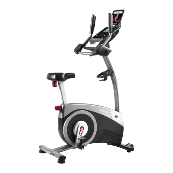
Model No. PFEX14817.0
Serial No.
Write the serial number in the
space above for reference.
ACTIVATE YOUR
WARRANTY
To register your product and
activate your warranty today,
go to my.proform.com.
CUSTOMER CARE
For service at any time, go to
proformservice.com.
Or call 1-888-533-1333
Mon.–Fri. 6 a.m.–6 p.m. MT
Sat. 8 a.m.–12 p.m. MT
Please do not contact the store.
CAUTION
Read all precautions and
instructions in this manual before
using this equipment. Keep this
manual for future reference.
Serial Number
Decal
USER'S MANUAL
Advertisement
Table of Contents

Related Manuals for Pro-Form 8.0 EX


Summary of Contents for Pro-Form 8.0 EX
- Page 1 proform.com USER’S MANUAL Model No. PFEX14817.0 Serial No. Write the serial number in the space above for reference. Serial Number Decal ACTIVATE YOUR WARRANTY To register your product and activate your warranty today, go to my.proform.com. CUSTOMER CARE For service at any time, go to proformservice.com.
-
Page 2: Table Of Contents
TABLE OF CONTENTS WARNING DECAL PLACEMENT ............. . .2 IMPORTANT PRECAUTIONS . -
Page 3: Important Precautions
IMPORTANT PRECAUTIONS WARNING: To reduce the risk of serious injury, read all important precautions and instructions in this manual and all warnings on the exercise bike before using the exercise bike. ICON assumes no responsibility for personal injury or property damage sustained by or through the use of this product. - Page 4 STANDARD SERVICE PLANS...
-
Page 5: Before You Begin
Thank you for selecting the revolutionary PROFORM reading this manual, please see the front cover of this ® 8.0 EX exercise bike. Cycling is one of the most effec- manual. To help us assist you, note the product model tive exercises for increasing cardiovascular fitness, number and serial number before contacting us. -
Page 6: Part Identification Chart
PART IDENTIFICATION CHART Use the drawings below to identify the small parts needed for assembly. The number in parentheses below each drawing is the key number of the part, from the PART LIST near the end of this manual. The number following the key number is the quantity needed for assembly. -
Page 7: Assembly
ASSEMBLY • To hire an authorized service technician to • To identify small parts, see page 6. assemble this product, call 1-800-445-2480. • In addition to the included tool(s), assembly • Assembly requires two persons. requires the following tools: one Phillips screwdriver •... - Page 8 3. Set a sturdy piece of packing material under the front of the Frame (1). Attach the Front Stabilizer (2) to the Frame (1) with two M10 x 98mm Screws (53). Then, remove the packing material. 4. Raise the Upright (4) to the vertical position. Have a second person hold the Upright until you complete this step.
- Page 9 5. Attach the Accessory Tray (8) to the Upright (4) with an M6 x 50mm Screw (89). 6. Have a second person hold the Handlebar (5) near the Upright (4). See the inset drawing. Route the Upper Wire (87) through the Pivot Post (78) and the Pivot Bracket (71) as shown.
- Page 10 7. IMPORTANT: Turn the Console Knob (77) until the Pivot Bracket (71) is in the most vertical position. While a second person holds the Console (13) near the Pivot Bracket (71), connect the wires on the Console to the Upper Wire (87) and the Pulse Wire (61).
- Page 11 9. Remove the Seat Knob (26) from the Seat Bracket (30) inside the Seat Carriage (24). Next, hold the Seat Carriage (24) on the Seat Post (6). Insert the Seat Knob (26) upward into the Seat Post, and tighten the Seat Knob into the Seat Bracket (30) inside the Seat Carriage.
- Page 12 11. Identify the Right Pedal (21). Using an adjustable wrench, firmly tighten the Right Pedal (21) clockwise into the Right Crank Arm (19). Firmly tighten the Left Pedal (not shown) counterclockwise into the Left Crank Arm (not shown). IMPORTANT: You must turn the Left Pedal counterclockwise to attach it.
-
Page 13: How To Use The Exercise Bike
HOW TO USE THE EXERCISE BIKE HOW TO PLUG IN THE POWER ADAPTER HOW TO ADJUST THE LATERAL POSITION OF THE SEAT IMPORTANT: If the exercise bike has been exposed to cold temperatures, allow it to warm to room To adjust the lateral temperature before you plug in the power adapter. - Page 14 HOW TO ADJUST THE CONSOLE HOW TO USE THE TABLET HOLDER The console can be IMPORTANT: The tablet holder (F) is designed for use with most full-size tablets. Do not place adjusted to several any other electronic device or object in the tablet angles.
- Page 15 CONSOLE DIAGRAM FEATURES OF THE CONSOLE resistance of the pedals as it guides you through an effective workout. The advanced console offers an array of features designed to make your workouts more effective and You can even connect your personal audio player to enjoyable.
- Page 16 HOW TO USE THE MANUAL MODE Pulse (BPM)—This display will show your heart rate in beats per minute (bpm) when you use the 1. Begin pedaling or press any button on the handgrip heart rate monitor or the optional chest console to turn on the console.
- Page 17 Press the Home button to exit the workout and When your pulse is detected, your heart rate will return to the main menu. If necessary, press the appear in the display. For the most accurate Home button again. heart rate reading, hold the contacts for at least 15 seconds.
- Page 18 HOW TO USE AN ONBOARD WORKOUT in the display for a few seconds to alert you. The resistance of the pedals will then change. 1. Begin pedaling or press any button on the console to turn on the console. As you exercise, keep your pedaling speed near the target RPM for the current segment.
- Page 19 HOW TO CONNECT YOUR TABLET TO THE 5. Disconnect your tablet from the console if CONSOLE desired. The console supports BLUETOOTH connections to To disconnect your tablet from the console, first tablets via the iFit Bluetooth Tablet app and to compat- select the disconnect option in the iFit Bluetooth ible heart rate monitors.
- Page 20 HOW TO USE THE SOUND SYSTEM HOW TO CHANGE CONSOLE SETTINGS To play music or audio books through the console 1. Select the settings mode. sound system while you exercise, plug a 3.5 mm male to 3.5 mm male audio cable (not included) into the To select the settings mode, press the gear button.
-
Page 21: Maintenance And Troubleshooting
MAINTENANCE AND TROUBLESHOOTING MAINTENANCE HOW TO ADJUST THE DRIVE BELT Regular maintenance is important for optimal If the pedals slip while you are pedaling, even while the performance and to reduce wear. Inspect and properly resistance is adjusted to the highest setting, the drive belt may need to be adjusted. - Page 22 HOW TO ADJUST THE REED SWITCH Locate the Reed Switch (57). Rotate the Left Crank Arm (20) until a Magnet (55) is aligned with the Reed If the console does not display correct feedback, the Switch. Then, loosen the M5 x 16mm Flat Head Screw reed switch should be adjusted.
-
Page 23: Fcc Information
FCC INFORMATION This equipment has been tested and found to comply with the limits for a Class B digital device, pursuant to Part 15 of the FCC Rules. These limits are designed to provide reasonable protection against harmful interference in a residential installation. This equipment generates, uses, and can radiate radio frequency energy and, if not installed and used in accordance with the instructions, may cause harmful interference to radio communications. -
Page 24: Exercise Guidelines
EXERCISE GUIDELINES Burning Fat—To burn fat effectively, you must exer- WARNING: cise at a low intensity level for a sustained period of Before beginning this time. During the first few minutes of exercise, your or any exercise program, consult your physi- body uses carbohydrate calories for energy. -
Page 25: Part List
PART LIST Model No. PFEX14817.0 R0917A Key No. Qty. Description Key No. Qty. Description Frame Knob Nut Front Stabilizer M8 x 76mm Bolt Rear Stabilizer J-bolt Upright #10 x 12mm Screw Handlebar M10 x 98mm Screw Seat Post Drive Belt Rear Shield Cover Magnet Accessory Tray... -
Page 26: Exploded Drawing
EXPLODED DRAWING A Model No. PFEX14817.0 R0917A... - Page 27 EXPLODED DRAWING B Model No. PFEX14817.0 R0917A...
-
Page 28: Ordering Replacement Parts
ORDERING REPLACEMENT PARTS To order replacement parts, please see the front cover of this manual. To help us assist you, be prepared to provide the following information when contacting us: • the model number and serial number of the product (see the front cover of this manual) •...
Need help?
Do you have a question about the 8.0 EX and is the answer not in the manual?
Questions and answers