Table of Contents
Advertisement
Quick Links
Advertisement
Table of Contents

Related Manuals for Icom GM600


Summary of Contents for Icom GM600
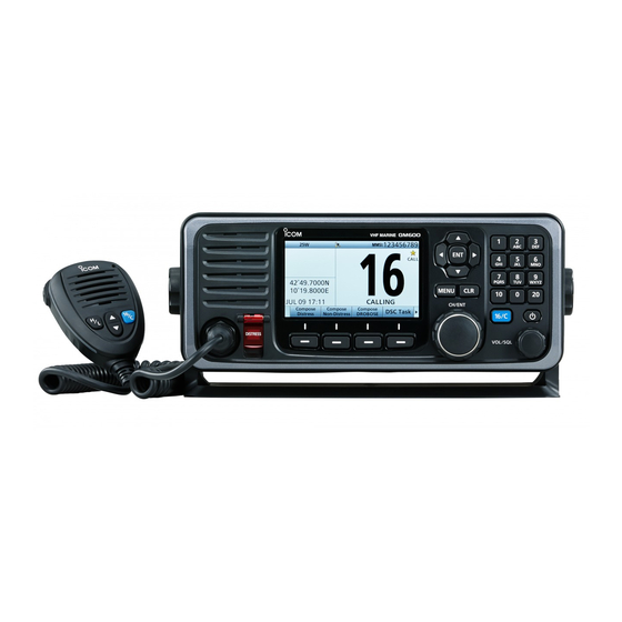
- Page 1 INSTRUCTION MANUAL VHF MARINE TRANSCEIVER GM600...
-
Page 2: Explicit Definitions
Thank you for choosing this Icom product. EXPLICIT DEFINITIONS This product is designed and built with Icom’ s state of the art technology and craftsmanship. WORD DEFINITION With proper care, this product should provide you with years of trouble-free operation. -
Page 3: In Case Of Emergency
It is recommended that antenna of a maximum gain of 3 dB is used. If higher gain antenna are required then USING DIGITAL SELECTIVE CALLING (Ch 70) please contact your Icom distributor for revised installation DISTRESS CALL PROCEDURE recommendations. 1. While lifting up the key cover, hold down [DISTRESS]... - Page 4 PRECAUTIONS RWARNING! NEVER connect the transceiver to an AC outlet. DO NOT use harsh solvents such as Benzine or alcohol to This may pose a fire hazard or result in an electric shock. clean the transceiver, as they will damage the transceiver’s surfaces.
-
Page 5: Action Icon Description
Rotate disasters, disturbances, riots, war, or radioactive : Rotate [CH/ENT] to select. contamination. • The use of Icom transceivers with any equipment that is Push not manufactured or approved by Icom. : Push [ENT] to enter or set. Push : Push the keypad to enter a digit or text. - Page 6 TABLE OF CONTENTS IMPORTANT ..................i ■ DSC Task mode ..............33 EXPLICIT DEFINITIONS ..............i ■ Sending a Distress call ............35 DISPOSAL ..................i ■ Sending a Non-Distress call ..........48 IN CASE OF EMERGENCY ............. ii ■ Receiving DSC calls ............. 60 ■...
-
Page 7: Operating Rules
OPERATING RULES D Priorities (2) OPERATOR’S LICENSE • Read all rules and regulations pertaining to call priorities, A Restricted Radiotelephone Operator Permit is the license and keep an up-to-date copy handy. Safety and distress most often held by small vessel radio operators when a calls take priority over all others. -
Page 8: Panel Description
PANEL DESCRIPTION ■ Front panel q DISTRESS KEY [DISTRESS] w ENTER KEY [ENT] e LEFT AND RIGHT KEYS [Ω]/[≈] r UP AND DOWN KEYS [∫]/[√] Speaker Function display (p. 6) t KEYPAD y POWER KEY [ ] u CHANNEL 16/ CALL CHANNEL KEY [16/C] MIC CONNECTOR !2 SOFTWARE KEYS... - Page 9 PANEL DESCRIPTION q DISTRESS KEY [DISTRESS] (p. 35) u CHANNEL 16/CALL CHANNEL KEY [16/C] Hold down for 3 seconds to transmit a Distress call. ➥ Push to select Channel 16. (p. 13) ➥ Hold down for 1 second to select the Call channel. w ENTER KEY [ENT] (p.
- Page 10 PANEL DESCRIPTION ■ Front panel (Continued) !2 SOFTWARE KEYS (p. 5) Channel [CH] (p. 13) You can use various key functions that are assigned to the Software Keys, as described below. When Channel 16 or the Call channel is selected, push to select the last selected channel.
- Page 11 PANEL DESCRIPTION ■ Software Key function ■ Microphone The transceiver has the Software Keys for various functions. q PTT SWITCH Microphone The key function is displayed above the Software Key, as [PTT] shown below. w UP/DOWN KEYS D Selecting the Software Key function r CHANNEL 16/ [Y]/[Z] When “Ω”...
-
Page 12: Function Display (Main Screen)
PANEL DESCRIPTION ■ Function display (Main screen) q Status area D Status area w Task area e Information area r Channel area The current status is displayed in the Status area. Indicator Description SCAN 16 Displayed during a Priority scan. (p. 27) SCAN Displayed during a Normal scan. -
Page 13: D Information Area
PANEL DESCRIPTION D Information area D Channel area The 9 digit MMSI (Maritime Mobile Service Identity: DSC The selected operating channel number, channel name, and self ID) code and the following indicators are displayed in the following indicators are displayed in the Channel area. the Information area. - Page 14 PANEL DESCRIPTION ■ Function display (Main screen) (Continued) D Position and Time area POSITION AREA TIME AREA The current position is displayed when valid GPS data has ➥ The current time is displayed when valid GPS data has been received, or the position was manually entered. been received, or the time was manually entered.
-
Page 15: Entering The Mmsi Code
PREPARATION ■ Entering the MMSI code First, you must enter the 9 digit MMSI e Enter your 9 digit MMSI code. y After entering the 9th digit, register (Maritime Mobile Service Identity: DSC the ID. Push self ID) code at power ON. Push You can perform this initial code Rotate... -
Page 16: Menu Screen
MENU SCREEN You can use the Menu screen to set • Compose Distress (p. 36) • Latitude Displays latitude data. infrequently changed values or function Nature of Distress Selects a Nature of • Longitude Displays longitude data. Distress option. settings. •... - Page 17 MENU SCREEN • Internal Turns the Internal Speaker • CH 70 SQL Selects the Channel 70 Speaker function ON or OFF. Level squelch level. • MIC Type Selects a microphone type. • Auto Print Turns the Auto Print function ON or OFF. Radio •...
- Page 18 MENU SCREEN ■ Selecting a Menu item Follow the procedures as described r Rotate [CH/ENT] to select below to select a Menu item. “Dual/Tri-Watch,” then push [ENT]. Rotate Example: Sets the Tri-watch function. q Push [MENU] to display the Menu screen.
-
Page 19: Basic Operation
BASIC OPERATION ■ Selecting a channel D Selecting a regular channel D Selecting Channel 16 D Selecting the Call channel Channel 16 is the distress and safety You can set a Call channel for quick Selecting a channel in sequence: channel. - Page 20 BASIC OPERATION ■ Setting the Call channel ■ Selecting a channel (Continued) You can set the Call channel with your r Rotate [CH/ENT] to select TIP: After receiving a signal, or you most often-used channel for quick recall. “Call Channel,” then push [ENT]. operate the transceiver, the transceiver enters the Radio Telephone (RT) mode.
- Page 21 BASIC OPERATION ■ Receiving and transmitting t Rotate [VOL/SQL] to adjust the NOTE: CAUTION: DO NOT Transmit without squelch level until the noise just Selecting a channel: an antenna. disappears. • While receiving a signal, “ ” is displayed. y Select a channel. (p. 13) •...
- Page 22 BASIC OPERATION ■ Receiving and transmitting (Continued) w Turn ON the transceiver IMPORTANT: To maximize the readability of your transmitted y Select a channel signal at a receiver station, pause a second after pushing [PTT], and then hold the microphone 5 to 10 cm from your mouth and speak at your normal voice level.
- Page 23 BASIC OPERATION ■ Backlight function ■ Microphone Lock function The function display and keys can be • In the Backlight Settings window, if you backlit for better visibility under low light push no key for about 5 seconds, the The Microphone Lock function conditions.
- Page 24 BASIC OPERATION ■ Entering a Channel name You can rename each channel with a r Enter the desired character. Using [Y], [Z], [Ω], or [≈]: unique alphanumeric ID of up to 10 Push [Y], [Z], [Ω], or [≈] to select characters.
- Page 25 BASIC OPERATION Common operation • To enter a symbol: Select “!$?,” and then push [ENT]. Push [Y], [Z], [Ω], or [≈] to select the desired character, and then push [ENT]. • To enter a space: Push [Y], [Z], [Ω], or [≈] to select “Space,”...
- Page 26 When an alert is received: “Aggregation” functions, but the • An icon is displayed or blinks in the GM600 cannot use these functions. information area. • A popup screen is displayed with the icon. Example (Receiving a Distress Call):...
- Page 27 BASIC OPERATION You can receive the following alerts from the transceiver. • See page 111 for details of the alerts. • See page 22 for details of the category and priority. Category Priority Event Popup screen Warning • A Distress call is received. See “DSC •...
- Page 28 Caution. You can receive alerts of the alerts from multiple bridge equipment. ( Settings > Configuration > BAM > “Warning” and “Caution” priorities. The GM600 can be connected to the Function) CAM system. e Select “ON,” and then push [ENT].
- Page 29 BASIC OPERATION D Icon and Status When the GM600 receives a request The icon varies, depending on the alert’s priority and status, as shown below. for responsibility transfer from the CAM Priority Icon Status Description Audible signal system: • The alert status becomes “Active –...
- Page 30 BASIC OPERATION ■ Bridge Alert Management (BAM) (Continued) D BAM List The BAM List screen displays the q Push [MENU]. BAM List screen received alerts. When the alert w Select “BAM List,” and then push status changes to “Normal,” the alert [ENT].
-
Page 31: D Software Key Functions
BASIC OPERATION D Software Key functions When entering the BAM List screen, the following functions are displayed. When entering the details screen of the selected alert by pushing [Details] Function Description Function Description the following functions are displayed. Home Push to return to the Main Push to return to the first Function Description... -
Page 32: Scan Operation
[CH/ENT]. • Set the desired channels you want to scan as Favorite channels. (Scans only Favorite channels.) (p. 27) The GM600 has two scan types. • Set the desired scan type to “Normal" or “Priority.” • Priority scan (default) (p. - Page 33 SCAN OPERATION ■ Favorite channels ■ Starting a scan You can quickly recall often-used channels by setting them as q Push [Scan] to start a scan. Favorite channels. • During a Priority scan, “SCAN 16” is displayed. All channels are set as Favorite channels by default. During a Normal scan, “SCAN”...
-
Page 34: Dual Watch
DUALWATCH/TRI-WATCH ■ Description ■ Operation Dualwatch and Tri-watch are convenient to periodically q Select Dualwatch or Tri-watch in the Menu screen. (p. 90) check Channel 16 while you are operating on another w Select a channel. (p. 13) channel. e Push [Dual Watch] or [Tri Watch] to start Dualwatch or Tri-watch. -
Page 35: Dsc Operation
DSC OPERATION ■ DSC address ID You can enter a total of 100 DSC r Enter a 9 digit Individual ID. u After entering, select “Finish,” and address IDs (Individual ID: 75, Group then push [ENT]. Push ID: 25), and assign a name of up to 10 Push characters. - Page 36 DSC OPERATION ■ DSC address ID (Continued) D Entering Group ID D Deleting an entered ID q Push [MENU]. t After entering all 9 digits, select q Push [MENU]. w Select “Group ID,” then push [ENT]. “Next,” and then push [ENT]. w Select “Individual ID”...
- Page 37 DSC OPERATION ■ Entering the position and time A Distress call should include the ship’s e Enter your latitude position. t Enter your longitude position. position and time. Push Push If no GPS data is received, you should manually enter your position (latitude and longitude) and Universal Time Enter Enter...
- Page 38 DSC OPERATION ■ Entering the position and time (Continued) u Enter your UTC time. When position and time data are set, NOTE: While entering: Push Latitude, Longitude and UTC time are • To move the cursor: displayed. Rotate [CH/ENT]. Enter •...
- Page 39 DSC OPERATION ■ DSC Task mode D Activating the held DSC task The transceiver can hold up to 7 tasks. In the Task mode, you can hold or You can handle more than 2 DSC tasks activate the DSC task as follows. q Push [Task List] to display the simultaneously by switching between...
- Page 40 DSC OPERATION ■ DSC Task mode (Continued) D Task List D Devices List You can display the Task List screen by On the Task List screen, the following You can display the Devices List screen pushing [Task List] Software keys are displayed. by pushing [Devices List] when a The number of tasks is displayed at the...
-
Page 41: D Simple Call
DSC OPERATION ■ Sending a Distress call e After sending, the following screen is NEVER MAKE A DISTRESS CALL IF TIP: If you want to compose a Distress displayed. YOUR SHIP OR A PERSON IS NOT call, see ʻRegular call.ʼ (p. 36) IN AN EMERGENCY. -
Page 42: D Regular Call
DSC OPERATION ■ Sending a Distress call (Continued) D Regular call You can compose the Distress call. w Select the desired option, then push e After entering, select “Finish,” and [ENT]. then push [ENT]. Step 1. Display the Compose (Example: Fire, Explosion) Distress screen Step 4. - Page 43 DSC OPERATION w After sending, the following screen is Step 5. Replying NOTE: displayed. Transmitting: q When the acknowledgment is • A distress alert default contains: received: - Nature of distress: • An alarm sounds. Undesignated distress (Simple call) • The following screen is displayed. Selected in Step 2 (Regular call) - Position information: The latest GPS or manual input...
-
Page 44: D Resending A Distress Call
DSC OPERATION ■ Sending a Distress call (Continued) D Resending a Distress call e Enter your position and time data. • See page 31 for entering details. While waiting for an acknowledgment, y When the acknowledgment is r After entering, select “Finish,” and you can resend the call. -
Page 45: D Sending A Distress Cancel Call
DSC OPERATION D Sending a Distress Cancel call w Push [OK] to send a Distress While waiting for an acknowledgment, r Hold down [PTT] to announce your you can send a Distress Cancel call. Cancel call. cancel statement. • Rotate [CH/ENT] to view the cancel statement of the Distress Cancel call. - Page 46 DSC OPERATION ■ Sending a Distress call (Continued) D Sending a Distress acknowledgment Distress call reception should stop q When a Distress call is received: t Push [ACK (Distress)] after one sequence because the • An alarm sounds. coast station should send back an •...
- Page 47 DSC OPERATION o Hold down [PTT] to communicate u Push [Call] to send a Distress TIP: acknowledgment. with the ship in distress. When a Distress call related to !0 Push [Home] to return to the MOB (Man Overboard) is received: Main screen.
-
Page 48: D Sending A Distress Relay Call
DSC OPERATION ■ Sending a Distress call (Continued) D Sending a Distress Relay call q Push [Compose DROBOSE] There are two ways to transmit the Distress r Select “Address,” then push [ENT]. Relay call—“Distress Relay On Behalf Of to display the Compose DROBOSE t Select the desired coast station screen. - Page 49 DSC OPERATION u Select “Manual Input,” then push o After entering, select “Finish,” and !2 Select “Position,” then push [ENT]. [ENT]. then push [ENT]. Rotate !0 Select “Nature of Distress,” then Rotate push [ENT]. !1 Select the desired option, then push Push [ENT].
- Page 50 DSC OPERATION ■ Sending a Distress call (Continued) D Sending a Distress Relay call (Continued) !5 Push [Call] to send the Distress !7 When the acknowledgment is !8 Hold down [PTT] to communicate. received: !9 Push [Home] to return to the Relay call.
- Page 51 DSC OPERATION To transmit the distress relay call e Select the desired message type. When you select “Manual Input” in step with “Distress Call Log”: (Example: Individual) t, push the keypad to manually enter You can relay a Distress call after Rotate the desired Individual ID.
- Page 52 DSC OPERATION ■ Sending a Distress call (Continued) D Sending a Distress Relay call (Continued) i Push [Call] to send the Distress o After sending, the following screen is • When the BAM function (p. 20) is displayed. OFF: The backlight blinks and the Relay call.
- Page 53 DSC OPERATION D Sending a Distress Relay acknowledgment You can send the Distress Relay u Hold down [PTT] to communicate. t Push [ACK (Relay)] acknowledgment only when the i Push [Home] to return to the Distress Relay call is received. Main screen.
-
Page 54: D Sending An Individual Call
DSC OPERATION ■ Sending a Non-Distress call To ensure correct operation of the DSC e Select the desired individual q Push [Compose Non-Distress] function, confirm you correctly set the to display the Compose Non-Distress address, or “Manual Input,” then Channel 70 squelch level. (p. 81) push [ENT]. - Page 55 DSC OPERATION !0 When the acknowledgment is r Select “Category,” then push [ENT]. i Push [Call] to send the received: t Select the desired option, then push Individual call. • An alarm sounds. [ENT]. • The following screen is displayed. (Example: Routine) (Example: ACK (Able)) Rotate...
- Page 56 DSC OPERATION ■ Sending a Non-Distress calls (Continued) D Sending an Individual call (Continued) D Sending an Individual acknowledgment • When the BAM function (p. 20) is When receiving an Individual call, you r Push [≈] to scroll the Software Key OFF: The backlight blinks and the can send an acknowledgment (‘Able,’...
- Page 57 DSC OPERATION D Sending an All Ships call All ships, that have DSC transceiver, t Select the desired option, then push i Push [Call] to send the All ships use Channel 70 as their ‘listening [ENT]. call. channel.’ When you want to announce (Example: Safety) a message to these ships within range, Rotate...
-
Page 58: D Sending A Group Call
DSC OPERATION ■ Sending a Non-Distress calls (Continued) D Sending a Group call i Push [Call] to send the Group Rotate The Group call function allows you to call. transmit a DSC signal to only a specific group. Push q Push [Compose Non-Distress] to display the Compose Non-Distress screen. -
Page 59: D Sending A Position Request Call
DSC OPERATION D Sending a Position Request call Transmit a Position Request call when u After sending, the following screen is Rotate you want to know a specific ship’s displayed. current position, and so on. Push q Push [Compose Non-Distress] to display the Compose Non-Distress screen. - Page 60 DSC OPERATION ■ Sending a Non-Distress calls (Continued) D Sending a Position Request call D Sending a Position Request acknowledgment (Continued) When a Position Request call is received, [ACK Able]: • When the BAM function (p. 20) is you can send an acknowledgment. Sends an acknowledgment with OFF: The backlight blinks and the position and time data.
- Page 61 DSC OPERATION D Sending a Polling Request acknowledgment When a Polling Request call is received, you can send an acknowledgment. t Push [ACK] A Polling Request call enables the calling station to know a specific ship is within communication range, or not. q When a Polling Request is received: •...
-
Page 62: D Sending A Test Call
DSC OPERATION ■ Sending a Non-Distress calls (Continued) D Sending a Test call Testing on the exclusive DSC distress t Select the desired Individual y Push [Call] to send the Test call. and safety calling channels should be address, or “Manual Input.” avoided as much as possible by using (Example: STATION1) other methods. - Page 63 DSC OPERATION D Sending a Test call acknowledgment When a Test call is received, you can t Push [ACK] send an acknowledgment. q When a Test call is received: • An alarm sounds. w Push any [Close] • When the BAM function (p. 20) is OFF: Push any [Alarm OFF] e Push [Accept] •...
- Page 64 DSC OPERATION ■ Sending a Non-Distress calls (Continued) D Sending a Medical Transports call The Medical Transports call informs all r Select “Channel,” then push [ENT]. u After sending, the following screen is ships, by urgency priority, that your ship t Select the desired traffic channel, displayed.
- Page 65 DSC OPERATION D Sending a Ships and Aircraft call The Ships and Aircraft call informs all r Select “Channel,” then push [ENT]. u After sending, the following screen is ships that your ship is a neutral (not a t Select the desired traffic channel, displayed.
-
Page 66: D Receiving A Distress Call
DSC OPERATION ■ Receiving DSC calls q When a Distress call is received: [Accept]: Enters the DSC Task mode. NOTE: • An alarm sounds. To send the acknowledgment, After receiving a DSC call: • The following screen is displayed. push [Accept] •... - Page 67 DSC OPERATION D Receiving a Distress acknowledgment t Push [Relay]. TIP: q When a Distress acknowledgment When a Distress call related to sent to another ship is received: MOB (Man Overboard) is received: • An alarm sounds. Push [Devices List] in step t to •...
-
Page 68: D Receiving A Distress Cancel Call
DSC OPERATION ■ Receiving DSC calls (Continued) D Receiving a Distress Cancel call D Receiving a Distress Relay call D Receiving a Distress acknowledgment q When a Distress Relay call is received: • Enters the DSC Task mode. q When a Distress Cancel call is received: •... - Page 69 DSC OPERATION D Receiving a Distress Relay acknowledgment [Accept]: Enters the DSC Task mode. q When a Distress Relay • Automatically selects Channel 16, and then you should monitor it, because a To send the acknowledgment, acknowledgment is received: coast station may require assistance. push [Accept] •...
-
Page 70: D Receiving An Individual Call
DSC OPERATION ■ Receiving DSC calls (Continued) D Receiving an Individual call [Hold]: Holds the RX call task, r Push [≈] to scroll the Software Key NOTE: When the “Individual ACK” item and return to the previous functions. is set to “Auto (Unable),” the transceiver screen. - Page 71 DSC OPERATION D Receiving an Individual acknowledgment When receiving “ACK Able”: You can make voice communication • When the BAM function (p. 20) is • Automatically selects the channel that you specified when you sent the call for on the channel that you specified when OFF: The backlight blinks and the voice communication.
- Page 72 DSC OPERATION ■ Receiving DSC calls (Continued) D Receiving an Individual acknowledgment (Continued) When receiving “ACK Unable”: When receiving “ACK New CH”: You cannot make the voice • When the BAM function (p. 20) is You can make voice communication communication.
-
Page 73: D Receiving An All Ships Call
DSC OPERATION D Receiving an All Ships call q When an All Ships call is received: [Pause]: Push [Pause] to pause • An alarm sounds. • When the BAM function (p. 20) is the countdown. • The following screen is displayed. •... -
Page 74: D Receiving A Group Call
DSC OPERATION ■ Receiving DSC calls (Continued) D Receiving a Group call D Receiving a Geographical [Pause]: Pauses the countdown. Area call q When a Group call is received: • To restart the countdown, • An alarm sounds. q When a Geographical Area call (for push [Resume] •... -
Page 75: D Receiving A Position Request Call
DSC OPERATION D Receiving a Position Request Call [Hold]: NOTE: When “Position ACK” is set to Holds the RX call task, and return to [Pause]: Pauses the countdown. “Auto (Able),” the transceiver automatically • To restart the countdown, the previous screen. replies to the call. - Page 76 DSC OPERATION ■ Receiving DSC calls (Continued) D Receiving a Position Request acknowledgment D Receiving a Position Report call q When a Position Request • Rotate [CH/ENT] to view the call q When a Position Report call is contents. acknowledgment is received: received: w Push [Home] to return to the...
-
Page 77: D Receiving A Polling Request Call
DSC OPERATION D Receiving a Polling Request call [Accept]: [Hold]: Holds the RX call task, NOTE: When “Polling ACK” is set to Enters the DSC Task mode. and return to the previous “Auto,” the transceiver automatically screen. replies to the call. Both the TX and RX [Able]: Sends an acknowledgment. -
Page 78: D Receiving A Test Call
DSC OPERATION ■ Receiving DSC calls (Continued) D Receiving a Test call D Receiving a Test acknowledgment [Hold]: Holds the RX call task, NOTE: When “Test ACK” is set to “Auto,” q When a Test acknowledgment is and return to the previous the transceiver automatically replies to the received: screen. -
Page 79: D Receiving A Medical Transports Call
DSC OPERATION D Receiving a Medical Transports call q When a Medical Transports call is [Pause]: Pauses the countdown. received: • To restart the countdown, • Rotate [CH/ENT] to view the call push [Resume] contents. • An alarm sounds. [Accept]: Enters the DSC Task mode. w Push [Home] to return to the •... -
Page 80: D Receiving A Ships And Aircraft Call
DSC OPERATION ■ Receiving DSC calls (Continued) D Receiving a Ships and Aircraft call [Pause]: Pauses the countdown. q When a Ships and Aircraft call is • To restart the countdown, received: push [Resume] • An alarm sounds. [Accept]: Enters the DSC Task mode. •... -
Page 81: D Distress Message
DSC OPERATION ■ Received Call log D Distress message D Other messages The transceiver automatically stores up to 50 distress messages and 50 other q Push [DSC Log] to display the q Push [DSC Log] to display the messages, and they can be used as a Received Call Log screen. - Page 82 DSC OPERATION ■ Transmitted Call log The transceiver automatically stores q Push [MENU]. up to 50 transmitted calls, and the logs w Select “Transmitted Call Log.” can be used as a supplement to your ( DSC Log > Transmitted Call Log) logbook.
-
Page 83: Dsc Settings
DSC OPERATION ■ DSC settings Polling ACK D Position Input (See page 31) q Push [MENU]. Rotate D Individual ID (See page 29) w Select the desired item. D Group ID (See page 30) ( Settings > DSC > Individual ACK) ( Settings >... - Page 84 DSC OPERATION ■ DSC settings (Continued) D Setting the “Medical D Setting the “Ships and D Setting the CH Auto Switch Transports” item display Aircraft” item display option Selects whether or not to automatically option switch to channel 16 or the specified You can select whether the “Ships channel, or hold the call.
-
Page 85: D Setting The Alarm Status
DSC OPERATION D Setting the DSC Data Output D Setting the Alarm Status When receiving a DSC call from the This item is not displayed when the BAM function is turned ON. (p. 88) station that is selected in this setting, •... - Page 86 DSC OPERATION ■ DSC settings (Continued) D Setting the Alarm Status (Continued) • Self-Terminate • Discrete Selects whether or not to sound an Selects whether or not to sound an alarm when receiving the same Distress alarm when receiving a lower priority call.
-
Page 87: Squelch Level
DSC OPERATION D Setting the Channel 70 D Auto Print D Self Check Test Squelch level Selects whether or not to enable the The Self Check Test sends DSC signals Automatic Print Out function when a to the receiving AF circuit to compare Sets the squelch level on Channel 70. -
Page 88: Menu Items
MENU ITEMS ■ Menu items D Settings (p. 87) The Menu screen is constructed in a tree structure. (p. 87) • Configuration (p. 83) See page 12 to enter the Menu screen. Item Ref. Item Ref. Display p. 83 Inactivity Timer p. 86 Backlight p. - Page 89 MENU ITEMS ■ GPS Information • Mode (Settings > Configuration > Display > Mode) Sets the Backlight mode. Displays your position, date, time, Speed Over Ground • Day Mode: For the daytime operation, and the screen (SOG), and Course Over Ground (COG). items are in color.
- Page 90 MENU ITEMS ■ Configuration settings (Continued) D Display (Continued) • Night Mode Time q Enter the current time (if it is incorrect.) (Settings > Configuration > Display > Night Mode Time) Push Sets the period of time that the Backlight mode is automatically set to Night Mode when the “Mode”...
-
Page 91: D Key Beep
MENU ITEMS D Key Beep • Softkey 1 ~ 12 (Settings > Configuration > Key Assignment > Softkey 1 ~12) (Settings > Configuration > Key Beep) You can change which Software Key functions to display, and Turns the Key Beep function ON or OFF. their order. - Page 92 MENU ITEMS ■ Configuration settings (Continued) D UTC Offset D Inactivity Timer (Settings > Configuration > UTC Offset) (Settings > Configuration > Inactivity Timer) Sets the offset time between UTC (Universal Time Sets the inactivity timer to between 1 and 15 minutes Coordinated) and your local time to between –14:00 and (in 1 minute steps) or OFF.
- Page 93 MENU ITEMS • DSC Related • RT Related ( Settings > Configuration > Inactivity Timer > DSC Related) (Settings > Configuration > Inactivity Timer > RT Related) The transceiver automatically returns to the Main screen if no The transceiver automatically returns to the standby mode if key is pushed for this set time period.
- Page 94 MENU ITEMS ■ Configuration settings (Continued) D Position Data Output D BAM ( Settings > Configuration > NMEA Data Output > (Settings > Configuration > BAM) Position Data Output) Sets the BAM function. Selects whether or not to output your position data from the NMEA 0183 output port.
-
Page 95: D Internal Speaker
MENU ITEMS D Internal Speaker D MIC Type (Settings > Configuration > Internal Speaker) (Settings > Configuration > MIC Type) Turns the internal speaker ON or OFF. Selects the desired microphone type. When you want to mute the internal speaker, select “OFF.” •... -
Page 96: D Scan Type
MENU ITEMS ■ Radio settings D Scan Type D Dual/Tri-Watch (Settings > Radio > Scan Type) (Settings > Radio > Dual/Tri-Watch) Selects the desired Scan type to locate signals. (p. 26) Selects the desired watch type. (p. 28) • Normal Scan: Sequentially searches all Favorite channels. •... - Page 97 MENU ITEMS D Favorite Channel D Channel Display (Settings > Radio > Favorite Channel) (Settings > Radio > Channel Display) Sets the Favorite channel settings. You can select the number of digits to display the channel • Set All Channels: Sets all channels as Favorite channels.
-
Page 98: Connections And Maintenance
CONNECTIONS AND MAINTENANCE ■ Connections • Lead: Thicker than 0.75 sq mm, Length: Shorter than 1.5 m is recommended. SP (+) *VDR: Voyage Data Recorder SP (–) VDR* (–) VDR* (+) e D-SUB 25-PIN Connects to a printer (IBM ® centronics or compatible) to print out the received DSC call contents. -
Page 99: Antenna Connector
CONNECTIONS AND MAINTENANCE Remote alarm input terminal y ANTENNA CONNECTOR (to receive on Channel 70) When this terminal shorts to the GND terminal, the u ANTENNA CONNECTOR transceiver sends the Distress call. Connects to a marine VHF antenna with a PL-259 This terminal can be used as an external distress switch. - Page 100 ■ Connections (Continued) D Software maintenance A key element in the performance of any communication The Icom customer support center provides the firmware system is the antenna. Ask your dealer about antennas and file for the transceiver’s maintenance. You can update the the best place to mount them.
-
Page 101: Supplied Accessories
(12 V DC only) These illustrations are for the 8-pin connector. The following items are sold as a set with the GM600. PS-310 Be sure to set this ring to keep the waterproof capability. Screws (5 × 20 mm) -
Page 102: Power Source Connections
CONNECTIONS AND MAINTENANCE ■ Power source connections D Connecting to the DC power source through the PS-310 To operate the GM600, you must connect it to a 12 or 24 Screw Spring washer volt DC power source through the PS-310... -
Page 103: Mounting The Transceiver
CONNECTIONS AND MAINTENANCE ■ Mounting the transceiver Flat mounting The supplied universal mounting bracket with your transceiver enables overhead or flat mounting. • Mount the transceiver securely with the 5 supplied screws (5 × 20 mm) to a surface that is more than 10 mm thick and can support more than 5 kg. - Page 104 CONNECTIONS AND MAINTENANCE ■ Handset (HS-98) HS-98 The received audio is heard from: Speaker GM600 Status HS-98 switch internal or external speaker* On hook Cradle Speaker Off hook * Depending on the Internal Speaker setting. (p. 89) w HANDSET CONNECTOR...
-
Page 105: Specifications And Options
SPECIFICATIONS AND OPTIONS ■ Specifications This specification is described when the GM600 is used with • Maximum frequency deviation: ±5.0 kHz • Spurious emissions: Less than 0.25 µW the PS-310 dc power supply • Adjacent channel power: More than 70 dB All stated specifications are subject to change without notice •... - Page 106 Equipped with [Y]/[Z] (channel up/down), [H/L], [16/C], 93.5 and [PTT] keys, and a microphone. PS-310 * The same microphone as the microphone supplied with the transceiver. • CS-GM600 programming software • OPC-980 programming adapter cable • OPC-478UC/OPC-478UC-1 programming cable...
-
Page 107: Troubleshooting
TROUBLESHOOTING PROBLEM POSSIBLE CAUSE SOLUTION REF. The transceiver does • Bad connection to the power supply. • Check the connection to the transceiver p. 96 not turn ON. and power supply. • Fuse blows. • Repair the problem, and then replace the p. - Page 108 TROUBLESHOOTING PROBLEM POSSIBLE CAUSE SOLUTION REF. “NO POSITION” • A GPS receiver is not correctly connected. • Check the GPS receiver connection. p. 92 and “NO TIME” are • The position and time have not been • Enter the position and time. p.
-
Page 109: Channel List
CHANNEL LIST • International channels Frequency (MHz) Frequency (MHz) Frequency (MHz) Frequency (MHz) Frequency (MHz) Transmit Receive Transmit Receive Transmit Receive Transmit Receive Transmit Receive 156.050 160.650 156.800 156.800 1027 157.350 157.350 156.725 156.725 157.275 161.875 156.100 160.700 156.850 156.850 1028 157.400 157.400 156.775... - Page 110 DIGITAL INTERFACE (IEC61162-1) ■ I/O Sentences D Version number IEC61162-1 Ed.5(2016-08) D Input sentences (IEC61162-1) RMC, GGA, GNS, GLL, and VTG D Input sentence description • RMC—Recommended minimum specific GNSS data $**RMC, hhmmss.ss, A, llll.ll, a, yyyyy.yy, a, x.x, x.x, ddmmyy, x.x, a, a, a*hh<CR><LF> 10 11 12 13 1 UTC of position fix (000000.00 to 235959.99) 8 Course over ground, degrees true (0.0 to 360.0)
-
Page 111: Gll-Geographic Position - Latitude/Longitude
DIGITAL INTERFACE (IEC61162-1) • GNS—GNSS fix data $**GNS, hhmmss.ss, llll.ll, a, yyyyy.yy, a, c--c, xx, x.x, x.x, x.x, x.x, x.x, a*hh<CR><LF> 10 11 12 13 1 UTC of position (000000.00 to 235959.99) 8 HDOP (no use) 2 Latitude (0000.0000 to 9000.0000) 9 Antenna altitude, meters (no use) 3 N/S 10 Geoidal separation (no use) - Page 112 DIGITAL INTERFACE (IEC61162-1) ■ I/O Sentences (Continued) D Output sentences (IEC61162-1) DSC and DSE D Output interval DSC, DSE: Irregular output (Output immediately after receiving a DSC call.) D Output sentence description • DSC—Digital selective calling information $CDDSC, xx, xxxxxxxxxx, xx, xx, xx, x.x, x.x, xxxxxxxxxx, xx, a, a*hh<CR><LF> 9 10 11 1 Format specifier (2 digits) 7 Time or Telephone Number (Maximum 16 digits)
-
Page 113: D Version Number
DIGITAL INTERFACE (IEC61162-1) ■ BAM Sentences D Version number IEC61162-1 Ed.5(2016-08) D Input sentences (IEC61162-1) ACN and HBT D Input sentence description • ACN—Alert command $--ACN, hhmmss.ss, aaa, x.x, x.x, c, a*hh<CR><LF> 4 5 6 Release time of the alert command (000000.00 to 235959.99, or 4 Alert Instance (1 to 999999, NULL*) NULL) Alert command (A=Acknowledge, Q=Request/Repeat information,... - Page 114 DIGITAL INTERFACE (IEC61162-1) ■ BAM Sentences (Continued) D Output sentences (IEC61162-1) ALC, ALF, and ARC D Output interval ALC: 30 seconds ALF: Irregular output (Output immediately when an alert occurs or the content of the sentence is changed.) ARC: Irregular output (Output immediately when an ACN sentence cannot be accepted.) D Output sentence description •...
- Page 115 DIGITAL INTERFACE (IEC61162-1) • ALF—Alert sentence $--ALF, x, x, x, hhmmss.ss, a, a, a, aaa, x.x, x.x, x.x, x, c---c*hh<CR><LF> 1 2 3 5 6 7 10 11 12 13 1 Total number of ALF sentences for this message (1 to 2) 8 Manufacturer mnemonic code (NULL) 2 Sentence number (1 to 2) 9 Alert identifier...
- Page 116 DIGITAL INTERFACE (IEC61162-1) ■ Schematic diagram D IEC61162-1/BAM In/Out lines IEC61162-1/BAM_INPUT+ 3.3V TLP2303 TC7WU04FU LDTC143ZE IEC61162-1/BAM_INPUT IEC61162-1/BAM_INPUT- 2SC4213 IEC61162-1/BAM_OUTPUT+ ISL8483EIBZ IEC61162-1/BAM_OUTPUT- IEC61162-1/BAM_OUTPUT The input circuit is electricaly isolated by the TPL2303. ■ Hardware version Hardware version The transceiverʼs hardware version is described on the serial number label, is described here.
- Page 117 BAM ALERTS You can receive the following BAM alerts. • See page 20 for details of the BAM function. 3122 3122 3122 Priority Warning Warning Warning Category Acknowledge Responsibility transfer Yes Remove after rectified – – – Escalation properties Repeated as a warning after 90 seconds. Repeated as a warning after 90 seconds. Repeated as a warning after 90 seconds. Alert title DISTRESS: RX DISTRESS: RELAY...
- Page 118 BAM ALERTS 3122 3122 3123 Priority Warning Warning Caution Category Acknowledge – Responsibility transfer Yes – Remove after rectified – – – Escalation properties Repeated as a warning after 90 seconds. Repeated as a warning after 90 seconds. – • SAFETY: COM Alert title URGENCY: RX URGENCY: RX...
- Page 119 BAM ALERTS 3123 3123 3123 Priority Caution Caution Caution Category Acknowledge – – – Responsibility transfer – – – Remove after rectified – – – Escalation properties – – – • SAFETY: POS • SAFETY: POLL • SAFETY: TEST Alert title •...
- Page 120 BAM ALERTS 3123 3016 3013 Priority Caution Caution Caution Category Acknowledge – – – Responsibility transfer – – – Remove after rectified – – – Escalation properties – – – • SAFETY: POS Alert title SARPOSITION LOST DOUBTFUL POS • ROUTINE: POS •...
- Page 121 BAM ALERTS 3115 3079 Priority Warning Caution Category Acknowledge – Responsibility transfer Yes – Remove after rectified No – Escalation properties Repeated as a warning after 90 seconds. – Alert title IMPAIRED RADIO OOW ATTENTION Alert description PLL is unlocked DSC task is full You cannot transmit and receive.
- Page 122 INDEX Group ID entering ....30 Non-Distress call ..... 48 Accessory Dimensions (GM600/PS-310) 100 Individual acknowledgment All Ships call ....51 Accessory connectors set up .. 95 Discrete (Alarm Status) ... 80 ACK (Able) ...... 65 Group call ....52 Handset (HS-98) ....
- Page 123 INDEX Software Key area ....6 Dual/Tri-Watch ....90 Status area ......6 Maintenance ......94 FAV on MIC ..... 91 Safety (Alarm Status) ....79 Task area ....... 6 Antenna ....... 94 Favorite Channel ..... 91 Scan operation Fuse replacement ....94 Cleaning ......
- Page 124 How the World Communicates A7239D-7EU Printed in Japan 2022 Icom Inc. Sep. 2022 © 1-1-32 Kamiminami, Hirano-ku, Osaka 547-0003, Japan...
Need help?
Do you have a question about the GM600 and is the answer not in the manual?
Questions and answers