TESTO 570 Series Instruction Manual
Digital manifold
Hide thumbs
Also See for 570 Series:
- Instruction manual (34 pages) ,
- Instruction manual (34 pages) ,
- Instruction manual (34 pages)

Related Manuals for TESTO 570 Series


Summary of Contents for TESTO 570 Series
- Page 1 570s - digital manifold 0564 5701 0564 5702 0564 5703 0564 5704 Instruction manual...
-
Page 2: Table Of Contents
Disposal ....................9 Product-specific approvals ..............9 Intended use ..................9 Product description ................10 Overview of the testo 570s ..............10 Overview of main menu ................ 11 Control keys ..................12 First steps ................... 13 Charging the rechargeable battery ............13 Inserting batteries ................. - Page 3 Contents 7.5.3.2 Switching off ..................50 7.5.3.3 Manual probe selection ................ 51 Settings ....................52 7.6.1 Backlight duration ................53 7.6.2 Backlight brightness ................54 7.6.3 Auto Off ....................55 7.6.4 Auto Tfac (Temperature compensation factor) ........56 7.6.5 Units ....................57 7.6.6 Language .....................
- Page 4 Contents 8.8.2 Tutorial ....................83 8.8.3 Exclusion of liability ................83 testo DataControl archiving software ............ 84 8.9.1 System requirements ................84 8.9.1.1 Operating system ................. 84 8.9.1.2 PC ......................84 8.9.2 Procedure ..................... 84 Maintenance..................86 Calibration .................... 86 Cleaning the instrument ...............
-
Page 5: About This Document
1 About this document 1 About this document • The instruction manual is an integral part of the instrument. • Pay particular attention to the safety instructions and warning advice in order to prevent injury and damage to the product. •... -
Page 6: Safety And Disposal
• Only maintenance and repair work that is described in the documentation may be carried out on this instrument. Follow the prescribed steps exactly when doing the work. Only use original spare parts from Testo. Built-in rechargeable battery DANGER Risk of death! The built-in rechargeable battery can explode if it gets too hot. -
Page 7: Product-Specific Information
- For your own safety, you should return the measuring instrument to the Testo Customer Service for technical inspection. ACHTUNG Electrostatic charging may destroy the instrument. - Integrate all the components (system, manifold's valve block, refrigerant bottle, etc.) into the potential bonding (earthing). - Page 8 (e.g. category A2L, A2 and A3 of ISO 817), a hazardous and explosive atmosphere must always be expected in the immediate vicinity of the system. The testo 570s may only be operated outside of designated, recognizable or assumed explosion hazard zones (acc. to IEC 60079-10-1).
-
Page 9: Disposal
The instrument testo 570s is compatible with most non-corrosive refrigerants, water and glycol. The instrument testo 570s is not compatible with refrigerants containing ammonia. The testo 570s must not be used out of specified pressure and/or operation temperature range. The product must not be used in potentially explosive atmospheres! -
Page 10: Product Description
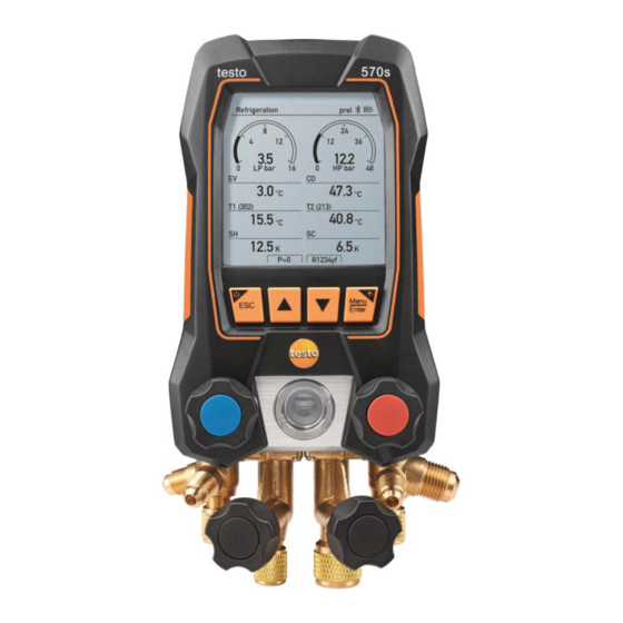
5 Product description 5 Product description Overview of the testo 570s Mini-DIN probe socket for NTC USB-C port for firmware update temperature probe, with socket and charging rechargeable cover battery Rear: • Battery compartment 3 Display. Instrument status icons •... -
Page 11: Overview Of Main Menu
Evacuation Pressure Leak Test Measuring mode Refrigerant Charging Target Superheat Compressor Test (DLT) Delta T ® Bluetooth Connection to the testo Smart App or Smart Probes Settings Backlight duration Backlight brightness Auto Off Auto Tfac (Temperature compensation factor) Units Language... -
Page 12: Control Keys
5 Product description Control keys Symbol Meaning • Open menu • Confirm input • Switch on the display illumination: Press and hold the key for >2s • Switch off the display illumination: Press and hold the key for >2s Change/navigate the display screen. •... -
Page 13: First Steps
Dispose of the instrument properly (observe local regulations) or return it to Testo for disposal. Only charge the battery using the original Testo mains unit supplied. The instrument indicates that the battery needs to be charged via a flashing battery symbol. -
Page 14: Inserting Batteries
6 First steps Inserting batteries The exchangeable batteries are the backup power to continue working with the device when the integrated lithium battery is empty, e. g. for long-term measurements. ✓ The instrument is switched off. Fold out the suspension hook, release the clip and remove the battery compartment lid. -
Page 15: Switching The Instrument On And Off
Settings menu. Setup wizard When the testo 570s is started up for the first time and after the factory settings have been reset, the setup wizard is activated and guides you step-by-step through the following setup parameters. The instrument setup that is implemented can be adapted at any time... -
Page 16: Using The Product
7 Using the product Take a photo of the QR code of the testo Smart App and press [Menu/Enter] to confirm. The measurement menu is displayed. 7 Using the product Preparing for measurement 7.1.1 Operating the valve positioners With respect to the refrigerant path, the digital manifold behaves just like a conventional four-way manifold: The passages are opened by opening the valves. -
Page 17: Automatic Mode
7 Using the product 7.1.2 Automatic mode The manifold automatically detects the pressure difference between the low- pressure and high-pressure sides. If the measured pressure on the low pressure side is 1 bar higher than on the high pressure side, a dialogue appears and the display can be changed accordingly. - Page 18 7 Using the product These can be fixed cable temperature probes or Testo Smart Probes (e.g. testo 115i). Before each measurement, check that the refrigerant hoses are in flawless condition. Before each measurement, zero the pressure sensors. All connections [▲] (P=O) must be pressureless (ambient pressure).
- Page 19 Connect the refrigerant hoses for low-pressure side (blue) and high- pressure side (red) to the measuring instrument. Connect the refrigerant hoses to the system. Connect testo 115i or fixed cable probes. Set refrigerant. Press the key [▼] (Rxx) (refrigerant number according to ISO 817).
- Page 20 To do this, the app must be connected to the instrument via Bluetooth. In the refrigerant list (App), you can now choose the refrigerant as a favourite by clicking on the star. The new favourite refrigerant will now be synchronized to the testo 570s. Note: During synchronization, the refrigerant list/selection on the instrument must remain closed.
-
Page 21: Evacuation
The testo 552i is recommended for carrying out the measurement. The measurement is also possible without the testo 552i, with testo 570s. However, this is not advisable due to insufficient accuracy. - Page 22 7 Using the product Measuring Mode menu is displayed. [▲] / [▼] Press to select Evacuation and press [Menu/Enter] confirm. Configure Target Lines menu is displayed. Adjust the Target Line value [▲] Press the key and in the Evacuation Target field, select Manual...
- Page 23 Press [Menu/Enter] to confirm. Confirm the entries in steps 4 and 5: [▼] Press to select and press [Menu/Enter] to confirm. ® A connection is established with available Bluetooth probes. testo 552i is switched on and connected automatically.
-
Page 24: Pressure Leak Test
7 Using the product Evacuation measurement menu is displayed. [▼] (Start) Start measurement: Press the key. Once the measuring range 0 to 20,000 microns / 0 to 26.66 mbar is reached, the current vacuum value is shown on the instrument display. The instrument also displays the current ambient temperature, the water evaporation temperature which... - Page 25 Surface temperature probes (e.g. testo 115i) can also be used for the temperature-compensated leakage testing, but must not be used to measure surface temperature. They must be positioned as far as possible to measure the air temperature.
- Page 26 Please note that only air probes are ideal for temperature- compensated leakage testing. testo 915i / testo 605i is switched on and automatically connected. Other temperature probes compatible with testo 570s can be connected.
-
Page 27: Target Superheat
7.2.4 Target Superheat This feature makes it possible to connect the testo 570s manifold to two additional testo 605i Smart Probes in order to calculate the target superheat. This application can only be used for split air conditioning systems/heat pumps with a fixed expansion valve. - Page 28 The values can either be configured manually via Manual Input recorded by the testo 605i via Smart Probe. When a Smart Probe selected, available testo 605i instruments are displayed for the connection. Adjust values for Outdoor Dry Bulb Temp. [▲] Press the key and in the Outdoor Dry Bulb Temp.
- Page 29 7 Using the product Press [Menu/Enter] to confirm. The field is activated. [▲] / [▼] Press to set the value. Press [Menu/Enter] to confirm. Adjust the Return Air Wet Bulb Temp. value [▲] / [▼] Press the key and in the Return Air Wet Bulb Temp.
- Page 30 Connect the refrigerant hoses for low-pressure side (blue) and high- pressure side (red) to the measuring instrument. Connect the refrigerant hoses to the system. Connect testo 115i/fixed cable probes. Set refrigerant. Press the key [▼] (Rxx) (refrigerant number according to ISO 817).
-
Page 31: Compressor Test (Dlt)
Bluetooth. The testo 115i (clamp thermometer) or fixed cable probes are used to carry out the measurement. Before each measurement, check that the refrigerant hoses are in flawless condition. - Page 32 7 Using the product [▲] / [▼] Press to select Measuring Mode and press [Menu/Enter] confirm. Measuring Mode menu is displayed. [▲] / [▼] Press to select Compressor Test (DLT) and press [Menu/Enter] to confirm. The measurement menu is displayed.
- Page 33 7 Using the product Connect 2 x testo 115i or 2 x fixed cable probes and third temperature probe to the compressor outlet. Set refrigerant. Press the key [▼] (Rxx) (refrigerant number according to ISO 817). The refrigerant menu opens and the current refrigerant is highlighted.
-
Page 34: Delta T
Delta T Temperature 1 and temperature 2 are measured. The difference is shown on the display as the delta temperature. Two testo 115i (clamp thermometers) or fixed cable probes are used to carry out the measurement. ✓ The instrument is switched on and the measurement menu is displayed. -
Page 35: Performing Long Time Measurement
When a long term measurement is done with the testo 770-3 Clamp Meter, the battery status of the testo 770-3 can´t be shown or considered in the testo 570s. The technician has to make sure, that the testo 770-3 has enough battery capacity for the planned logging time. -
Page 36: Refrigerant Charging
(9 measured values if connected with testo 770- When pressing any button a corresponding information message is shown. Refrigerant charging In combination with testo 560i and the testo Smart Valve the testo 570s offers multiple functions to charge refrigerant systems. -
Page 37: Manual Charging Via Weight
Manual charging via weight This function enables a refrigerant circuit to be charged manually via weight using the testo 560i in combination with the app or testo 570s manifold. By manually opening and closing the refrigerant bottle valve, the system is charged with refrigerant until the target value (weight/superheating/subcooling) is reached. - Page 38 7 Using the product Open connected valve(s) manually and add refrigerant to the system until the required value is reached. Charging manually means the user will need to control the charge by opening and closing valves with a manifold or other valves.
-
Page 39: Automatic Charging By Target Weight
Automatic charging by target weight This function enables the system to be charged automatically with an input target weight using the testo 560i scale and the testo Smart Valve in combination with the app or the testo 570s manifold. When using the manifold, the app is in second-screen mode. All settings must be made on the manifold. - Page 40 7 Using the product - In the manifold/app, select the proper refrigerant and select if pulsed charging is desired (on/off). Pulsed charging means that the valve opens and closes several times and the desired amount is thus filled in several small steps.
- Page 41 7 Using the product Enter Target Weight by selecting manual input and hit [START CHARGE] to start the process. The valve opens and attempts to fill with the set charge quantity. No pulsating charging takes place. Added refrigerant is displayed in g/kg increments on the manifold/app.
-
Page 42: Automatic Charging By Subcooling
Automatic charging by subcooling This function enables a refrigerant circuit to be charged via the target subcooling value using the testo 560i scale and the testo Smart Valve in combination with the app or testo 570s manifold. For this, the current subcooling value is determined. Based on this information, a target subcooling value can be entered. - Page 43 The system must be supervised by a competent person throughout the entire process. testo 560i and testo Smart Valve are connected via Bluetooth to the ✓ testo Smart App or the testo 570s manifold. testo 560i and testo Smart Valve are integrated into the refrigerant ✓...
- Page 44 7 Using the product Set the required target subcooling value to be reached on the manifold/app and hit [START CHARGE] to start the process. The valve opens and attempts to reach the set subcooling by charging refrigerant.
-
Page 45: Automatic Charging By Superheat
Automatic charging by superheat This function enables a refrigerant circuit to be charged via the target superheat value using the testo 560i scale and the testo Smart Valve in combination with the app or testo 570s manifold. For this, the current superheating value is determined. Based on this information, a target superheat value can be entered. - Page 46 7 Using the product testo 560i and testo Smart Valve are connected via Bluetooth to the ✓ testo Smart App or the testo 570s manifold. testo 560i and testo Smart Valve are integrated into the refrigerant ✓ circuit. Select the required refrigerant on the manifold/app and press [Menu/Enter] to confirm.
- Page 47 7 Using the product Set the required target superheat value to be reached on the manifold/app and hit [START CHARGE] to start the process. The valve opens and attempts to reach the set superheat by charging refrigerant. Added refrigerant is displayed in g/kg increments on the manifold/app.
-
Page 48: Bluetooth
The testo 570s has the option of establishing a Bluetooth connection with wireless probes as well as a connection to the testo Smart App at the same time. If the testo 570s is used with Smart Probes, they must be at least 20 cm apart. -
Page 49: Establishing A Connection
® Bluetooth 4.0. Once the connection between the app and the Testo manifold has been successfully established, the app is in second screen mode. This is indicated by a yellow frame in the app. This means that all measurement data from the manifold is being mirrored on the app. -
Page 50: Switching On
7 Using the product Bluetooth menu is displayed. 7.5.3.1 Switching on ✓ The Bluetooth menu is selected. 1 [Menu/Enter] In the On/Off switch icon, displayed. [▼] ® Enable Bluetooth : Press activate the [Completed] button and press [Menu/Enter] to confirm. -
Page 51: Manual Probe Selection
7 Using the product [▼] ® Disable Bluetooth : Press activate the [Competed] button and press [Menu/Enter] to confirm. ® ® When the Bluetooth icon is not shown on the display, Bluetooth switched off. 7.5.3.3 Manual probe selection If this menu is activated, it appears before a measurement. ✓... -
Page 52: Settings
7 Using the product Settings ✓ The instrument is switched on and the measurement menu is displayed. Press [Menu/Enter]. [▼] Select Settings: Press and then [Menu/Enter] to confirm. Settings menu is displayed. Available settings: • Backlight duration • Backlight brightness •... -
Page 53: Backlight Duration
7 Using the product 7.6.1 Backlight duration Set the backlight duration for the display. ✓ Settings menu is activated. [▲] / [▼] Press to select Backlight duration and press [Menu/Enter] confirm. Menu properties are displayed. [▲] / [▼] Press to select the backlight duration and press [Menu/Enter]... -
Page 54: Backlight Brightness
7 Using the product 7.6.2 Backlight brightness Set the brightness for the display. ✓ Settings menu is activated. [▲] / [▼] Press to select Backlight brightness and press [Menu/Enter] to confirm. Menu properties are displayed. [▲] / [▼] Press to select the brightness value (25%, 50%, 75%, 100%) and press... -
Page 55: Auto Off
7 Using the product 7.6.3 Auto Off You can manage the energy consumption for your instrument yourself. ✓ Settings menu is activated. [▲] / [▼] Press to select [Auto OFF] and press [Menu/Enter] to confirm. Menu properties are displayed. [▲] / [▼] Select using •... -
Page 56: Auto Tfac (Temperature Compensation Factor)
7 Using the product 7.6.4 Auto Tfac (Temperature compensation factor) A surface compensation factor has been set in the measuring instrument to reduce the measuring errors in the main field of applications. This reduces measuring errors when using surface temperature probes. Surface temperature probe An NTC temperature probe (accessory) must be connected for measuring the pipe temperature and for automatic calculation of... -
Page 57: Units
7 Using the product 7.6.5 Units ✓ Settings menu is activated. [▲] / [▼] Press to select [Units] press [Menu/Enter] to confirm. Menu properties are displayed. Adjustable units Measurement Unit Description parameter Temperature °C, °F Set unit for temperature. psi, kPa, MPa, Pressure Set unit for pressure. -
Page 58: Language
7 Using the product Measurement Unit Description parameter Micron, mbar, Vacuum Torr, mTorr pressure inH2O, hPa, Weight kg, g, lb, oz Press [ESC]: 1 x Unitsmenu, 2 x main menu view, 3 x measurement menu view. 7.6.6 Language ✓ Settings menu is activated. -
Page 59: Setup Wizard
7 Using the product 7.6.7 Setup Wizard ✓ Settings menu is activated. [▲] / [▼] Press to select [Setup Wizard] and press [Menu/Enter] confirm. Language selection opens. [▲] / [▼] Press to select the language. The units for the respective country are set automatically. ... -
Page 60: Restore Factory Settings
7 Using the product 7.6.8 Restore factory settings The instrument is reset to the factory settings. ✓ Settings menu is activated. [▲] / [▼] Press to select [Factory Reset] and press [Menu/Enter] confirm. Menu properties are displayed. [▲] / [Factory Reset] Start : Press... -
Page 61: Device Info
7 Using the product 7.6.9 Device Info ✓ Settings menu is activated. [▲] / [▼] Press to select [Instrument information] and press [Menu/Enter] to confirm. Instrument information menu is displayed. Press [ESC]: 1 x Units menu, 2 x main menu view, 3 x measurement menu view. -
Page 62: Smart App
8 Smart App 8 Smart App App – user interface Open main menu Display of the measurement period Display of calculated measurement results Reading for each probe Can be controlled with different function keys Instrument status bar Configuration Edit reading display Further symbols on the user interface (without numbering) One level back Exit view... -
Page 63: Main Menu
8 Smart App Search Favourite Delete Further information Display report Multiple selection Main menu Main menu can be accessed via the icon at top left. To exit the main menu, select a menu or right-click on the guided menus. The last screen displayed is shown. -
Page 64: Measurement Menu
® All Bluetooth probes compatible with the testo Smart App are displayed in the Basic view angezeigt. In all application menus, apart from the volume flow measurement, there are three different screens for the measurement - Live (or also Basic view), Graphic and Table. -
Page 65: Graphic View
8 Smart App 8.3.1.1 Graphic view In the Graphic view, the values for a maximum 4 channels can be displayed simultaneously in a chronological trend graph. All measured parameters can be displayed in the Graphic view via the channel selection (click on one of the four selection fields). -
Page 66: Refrigeration
With its integrated logging function the device can be left on the system and logging can be done without being on site. This allows an intelligent error analysis in the testo Smart App. The testo 115i clamp thermometer is used for the measurement. - Page 67 An NTC temperature sensor (accessory) must be connected for measuring the pipe temperature and for automatic calculation of superheating and subcooling. Testo Smart Probes (e.g. testo 115i) can be used. Before each measurement, check that the refrigerant hoses are in flawless condition.
- Page 68 8 Smart App Make the required settings. To start a log-term measurement, activate the option Long-term measurement with testo 570s. In case of Automatic start of long- term measurement, select Start date Start (time). For start type Manual long-term measurement can...
- Page 69 8 Smart App If the long-term measurement option is enabled, the configuration menu shows the remaining battery and rechargeable battery capacity and the maximum possible duration of the long-term measurement. Click on Apply Configuration. Despending on whether immediate measurement or long-term measurement should be started: Click on Start.
-
Page 70: Target Superheat
Target superheat This feature allows the manifold to calculate the target superheat in conjunction with the App and additional testo 605i Smart Probes. This application can only be used for split air conditioning systems/heat pumps with a fixed expansion valve. The two connected testo 605i Smart Probes determine the ODDB and RAWB values. - Page 71 8 Smart App Before each measurement, check that the refrigerant hoses are in flawless condition. Before each measurement, zero the pressure sensors. Click on Measure. Click on Target superheat. The Target superheat measurement menu opens. Click on Configuration menu opens. Make the required settings.
-
Page 72: System Leak Test
8 Smart App Set refrigerant. The newly set refrigerant is displayed in the refrigerant list. Click on Start. The measurement starts. Values currently being measured are displayed. Measured values can be saved or a new measurement can be started. 8.3.4 System Leak Test The temperature compensated leakage test can be used to check the leak... - Page 73 Surface temperature probes (e.g. testo 115i) can also be used for the temperature-compensated leakage test, but must not be used for measuring surface temperature. They must be positioned as far as possible to measure the air temperature.
-
Page 74: Evacuation
8 Smart App Click on Start. The measurement starts. Values currently being measured are displayed. Measured values are saved. The values can be exported or a report can be created. 8.3.5 Evacuation With the Evacuation application, foreign gases and moisture can be removed from the refrigeration circuit. - Page 75 8 Smart App Make the required settings. Click on Apply Configuration. Click on Start. The measurement starts.
-
Page 76: Customer
8 Smart App Values currently being measured are displayed. Measured values can be saved or a new measurement can be started. Customer In the Customer menu, all customer and measuring site information can be created, edited and deleted. Fields marked with * are mandatory. Without any information in this field, no customers or measuring sites can be stored. -
Page 77: Creating And Editing Measuring Sites
8 Smart App Store all relevant customer data. Click on Save. The new customer was saved. 8.4.2 Creating and editing measuring sites Click on Main menu opens Click on Customer. The Customer menu opens. Click on + New Customer. -
Page 78: Memory
Memory menu, you can call up all the measurements stored with the testo 570s, analyze them in detail and also create and save csv data and PDF reports. When clicking on a measurement, an overview of the measurement results is displayed. -
Page 79: Searching For And Deleting Measurement Results
8 Smart App 8.5.1 Searching for and deleting measurement results In the Memory menu, all stored measurements are sorted by date and time. Memory menu is open. ✓ Click on Search field with measurements opens. Enter the customer name or measuring site or date/time in the search field. -
Page 80: Sensors
8.6.1 Information Information is stored for each probe. The App is connected to testo 570s. ✓ Click on Main menu opens. Click on Sensors. -
Page 81: Settings
8 Smart App 8.6.2 Settings Settings can also be made for each probe. The probe is connected to the App. ✓ Click on Main menu opens. Click on Sensors. The Sensors menu opens. Click on one of the displayed probes. Click on the Settings tab. -
Page 82: Company Details
8 Smart App Click on Measurement settings. A window with different basic settings for measurement opens. Click on the required settings and change if necessary. The required measurement settings are set. Exit Measurement settings. 8.7.3 Company details Click on Settings. ... -
Page 83: Help And Information
8 Smart App Help and Information Under Help and Information, you will find information about the testo 550i, and the tutorial can be called up and implemented. This also where legal information can be found. 8.8.1 Instrument information Click on Help and Information. -
Page 84: Testo Datacontrol Archiving Software
Screen with a resolution of at least 800 x 600 pixels 8.9.2 Procedure To transfer the data from the App to testo DataControl, both ✓ instruments must be in the same network. For example: A notebook with installed testo DataControl and a smartphone with installed testo Smart App are connected to the same WLAN. - Page 85 8 Smart App Open the testo DataControl archiving software on the PC. Click on Select instrument. An overview with available instruments opens. Select instrument. A safety notice is displayed.
-
Page 86: Maintenance
The testo 570s is supplied with a factory calibration certificate as standard. Recalibration once every 12 months is recommended in many applications. This can be carried out by Testo Industrial Services (TIS) or other certified service providers. Please contact Testo for further information. Cleaning the instrument Do not use any aggressive cleaning agents or solvents! Mild household cleaning agents and soap suds may be used. -
Page 87: Keeping Connections Clean
> Carefully blow out oil residues in the valve block using compressed air. Ensuring measuring accuracy Testo Customer Service will be happy to help you as required. > Check the instrument regularly for leaks. Keep to the permissible pressure range! >... -
Page 88: Technical Data
6000 kPa/-0.1 to 6 Mpa/-1 to 60 bar (rel)/-14.7 to 870 psi Temperature measuring range: -50 to +150 °C / -58 to 302 °F Temperature measuring range of testo 115i: -40 to +150 °C / -40 to 302 °F Vacuum measuring range: 0 to 20,000 microns Overload 65 bar;... - Page 89 22 °C/71.6 °F) Temperature (-50 to 150 °C): ±0.5 °C (±1 digit), ±0.9 °F (±1 digit), testo 115i temperature: ±2.3 °F (-4 to 185 °F) / ±1.3 °C (-20 to +85 °C), Vacuum: ±(10 microns + 10% of m.v.) (100 to 1000 microns) - Logging duration time: 1 …...
- Page 90 >=145 h MCU+LCD.) Auto off 30 min, if enabled Display type: Illuminated LCD Response time: 0.5 s Directives, standards and EU Directive: 2014/30/EU tests You can find the EU declaration of conformity on the Testo website, www.testo.com, under the product- specific downloads.
- Page 91 10 Technical data Available refrigerants Feature Value No. of refrigerants ~ 90 Selectable refrigerants in the R114 R407C R444B instrument R407F R448A R123 R407H R449A R1233zd R408A R450A R1234yf R409A R452A R1234ze R410A R452B R124 R414B R453a R125 R416A R454A R420A R454B R134a...
-
Page 92: Tips And Assistance
Contact testo service E 15 E 16 E 30 testo 550s, 557s, 570s still runs the old firmware version. If you want use the latest version, please update again. If the error is still available, please contact our service department. E 31 testo 550s, 557s, 570s still runs the old refrigerant file version. -
Page 93: Status View
You can find up-to-date information on products, downloads and links to contact addresses for support queries on the Testo website at: www.testo.com. If you have any questions please contact your local dealer or the Testo Customer Service. You can find contact details on the back of this document or... - Page 94 Testo SE & Co. KGaA Celsiusstr. 2 79822 Titisee-Neustadt Germany Phone: +49 (0)7653 681-0 E-mail: info@testo.de www.testo.com 0970 5705 en 01 - 06.2023...
Need help?
Do you have a question about the 570 Series and is the answer not in the manual?
Questions and answers