Advertisement
Quick Links
Advertisement

Related Manuals for aivituvin AIR 52


Summary of Contents for aivituvin AIR 52
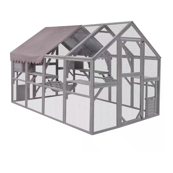
- Page 1 NSTRUCTION MANUAL AIR 52 www.aivituvin.com...
- Page 2 NOTICE Please retain these instructions for future Firmly secure all bolts,screws and knobs before use. Reconfirm that all bolts,screws,and knobs are secure every 90 days. Fasten screws loosely during initial assembly. Do not fully tighten screws until the item is completely assembled.
-
Page 3: Tools Required
TOOLS REQUIRED PHILLIPS DRILL 2PERSON APPROXIMATELY SCREWDRIVER (RECOMMENDED) ASSEMBLY 60MIN. ASSEMBLY HARDWARE M6.0x80 mm BOLT M6.0x70 mm BOLT 12PCS+1 spare 48PCS+1 spare M4.0x60 mm SCREW M3.5x50 mm SCREW 27PCS+1 spare 20PCS+1 spare M3.5x40 mm SCREW M3.5x30 mm SCREW 52PCS+1 spare 8PCS+1 spare M3.5x25 mm SCREW 16PCS+1 spare... - Page 4 Back Left Front Right...
- Page 5 PARTS CARTON 1/4 Lower left panel -front & back Back panel-down & middle Front panel-down & middle Back panel- upper & middle Front panel- upper & middle Waterproof Cover Hardware bag Layer Bottom of small house 2PCS 5PCS...
- Page 6 PARTS CARTON 2/4 Upper right panel- front & back Side panel Upper left panel-front & back 2PCS 2PCS 2PCS Bridge Left roof Roof supporting bar 2PCS 3PCS...
- Page 7 PARTS CARTON 3/4 Lower right panel -front & back Lower left panel -front & back Right roof 2PCS Right panel of small house Side panel Roof of small house 2PCS 2PCS 2PCS Left panel of small house Back panel of small house 2PCS 2PCS...
- Page 8 PARTS CARTON 4/4 Side panel Side supporting bar Layer supporting bar 6PCS 4PCS 10PCS Laryer supporting bar with hook Laryer supporting bar with hook fitting ( The hook fitting is on the fitting ( The hook fitting is on the right side) left side) 2PCS...
-
Page 9: Product Assembly
PRODUCT ASSEMBLY Connect the front panels, screw Part A, B, D, E, H, I by 14XP3. Attach side panel Part K to front side by 2XP4 screws in middle position and 2XP2 bolts in side position each side. - Page 10 PRODUCT ASSEMBLY ① Connect the back panels, screw Part A,B,C,E,G,I by 13XP3. ② Bolt the layer supporting bar Part N by 4XP2. Attach side panel Part K to back side by 2XP4 screws in middle position and 2XP2 bolts in side position each side.
- Page 11 PRODUCT ASSEMBLY Bolt 2 pieces of Part K together by 2XP1, then attach to front and back by 4XP1. Bolt the other side 2 pieces of Part K together by 2XP1, then attach to front and back by 4XP1.
- Page 12 PRODUCT ASSEMBLY Bolt the layer support bars Part N ,N1& N2 by 12XP2. (Position as shows in the picture) Bolt the layer support bars Part N ,N1 & N2 to the other side by 12XP2. (Position as shows in the picture)
- Page 13 PRODUCT ASSEMBLY Attach layer Part O by 4XP5 screws. (Position as shows in the picture) ① Attach layer Part O by 8XP5 screws. (Position as shows in the picture) ② Attach layer Part Q by 4XP5 screws. (Position as shows in the picture)
- Page 14 PRODUCT ASSEMBLY ① Attach layer Part O to the other side by 8XP5 screws. (Position as shows in the picture) ② Attach layer Part Q the other side by 4XP5 screws. (Position as shows in the picture)
- Page 15 PRODUCT ASSEMBLY ① Attach the 2 small houses, screw back panel Part U to side panel Part S&T by 4XP6, screw roof Part R by 4XP7. ② Screw the small house to the layer from the bottom by 4XP7 each.
- Page 16 PRODUCT ASSEMBLY Hook the bridge Part P to layers. Bolt side supporting bar Part M by 6XP2.
- Page 17 PRODUCT ASSEMBLY Bolt side supporting bar Part M to the other side by 6XP2. Attach roof Part F by 12XP5 screws. Velcro tape...
- Page 18 PRODUCT ASSEMBLY Attach roof Part V to the other side by 12XP5 screws. Velcro tape Open the door, walk into the cat run, and lock roof supporting bar Part L by 12XP4 screws.
- Page 19 PRODUCT ASSEMBLY Stick the Cover Part J by Velcro. Finish...
- Page 20 WARNING Manufacturer and seller expressly disclaim any and all liability for personal injury,property damage or loss,whether direct,indirect,or incidental,resulting from the incorrect attachment,improper use,inadequate miantenance,or neglect of this...
Need help?
Do you have a question about the AIR 52 and is the answer not in the manual?
Questions and answers
need manual for the little version of Air52-M
The manual for the aivituvin AIR 52 model can be found at www.aivituvin.com.
This answer is automatically generated