Table of Contents
Advertisement
Advertisement
Table of Contents

Summary of Contents for NXT Power INTEGRITY MAX L/T UPS Series
- Page 1 INTEGRITY MAX L/T UPS Line NPTU2000-O-N NPTU3000-O-N...
-
Page 2: Table Of Contents
Table of Contents 1. Safety Instructions and Storage/ Battery Care ............. 1 2. UPS Functional Descriptions .................. 2 2.1 Front Panel Display ..................... 2 2.2 Rear Panel ......................3 2.3 Communication Port Explanation ............... 4 3. Installation and Operation ..................4 3.1 Unpacking ...................... -
Page 3: Safety Instructions And Storage/ Battery Care
1. Safety Instructions and Storage/ Battery Care SAVE THESE INSTRUCTIONS - This manual contains important instructions that should be followed during installation and maintenance of the UPS and batteries. Read the instructions carefully to become familiar with the equipment before starting to install. Notify the carrier and dealer if there is any damage. -
Page 4: Ups Functional Descriptions
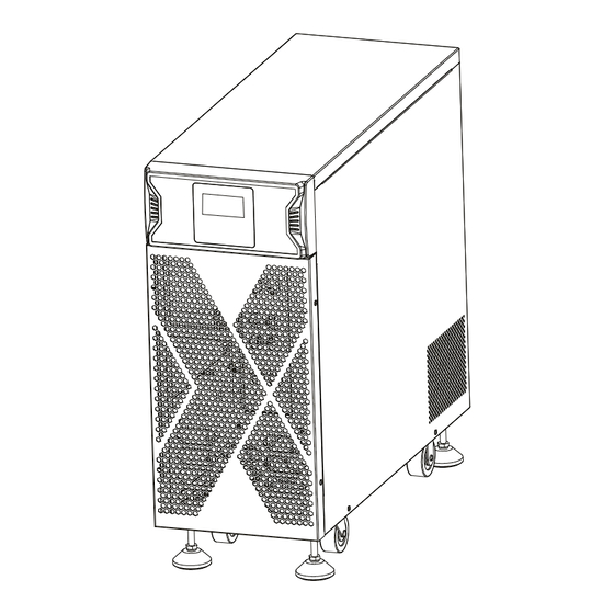
2. UPS Functional Descriptions 2.1 Front Panel Display 2.1.1 Tower < Convertible Type (Rack / Tower)> LCD panel LCD Panel Symbol Description UPS On/Alarm Silence UPS OFF Switch Special functions log in/out To re-confirm the change of UPS Setting Go to next page Go to previous page or change the setting of the UPS. -
Page 5: Rear Panel
2.2 Rear Panel IN TER FAC E U SB R S2 3 2 AC OU TPU T 1. Emergency Power Off (EPO) / Remote ON/OFF (ROO) Dry contact signal inputs 2. USB port 3. RS-232 port 4. Fan 5. External battery connector 6. -
Page 6: Communication Port Explanation
2.3 Communication Port Explanation The UPS is equipped with a true RS-232 communication port as standard to provide communication with bundled UPS monitoring software for remote monitoring of the UPS status using a PC. You may use optional interfaces cards for R2E (RS-232), RSE (RS-485), USE (second USB), DCE (Dry Contact), and SNMP. However, the R2E card, RSE card and USE card must not be used simultaneously. -
Page 7: Operation
3.3 Operation 3.3.1 LCD Panel Line mode start up Please ensure the outlet of power source is proper grounded. Ensure the voltage rating of power source is matched with UPS spec. Plug in UPS to the AC source UPS will start initializing after AC input power is available 5 seconds. LED/LCD indicator will be all lit and dim once and fan will start spinning. - Page 8 The procedures to release UPS from locked up status as below: (a) Check and record the error code. (b) Check user’s manual to understand possible cause, solve the problem or call service provider. (c) Press OFF key and hold for 5 seconds until twice beep heard. (d) Unplug AC input power cord or turn off power source switch.
- Page 9 Except for Buzzer (figures Q1 and Q2) and Self-test (figures R1 and R2) all of the other default settings may be changed by pressing the scroll up key. Figures S1 and S2 indicate the bypass input acceptable window. It follows the inverter output voltage. (i)Bypass Sensitivity Low: many selectable output voltages±15% and (ii)Bypass Sensitivity High: many selectable output voltages±10%.
-
Page 10: Ups System Block Diagram
4. UPS System Block Diagram Figure 4.1 Figure 4.1 illustrates the True On-Line Double Conversion architecture of the UPS system. The major modules consist of: 1) An AC-to-DC power converter (rectifier) with PFC control circuit 2) A DC-to-AC high frequency inverter 3) An intelligent battery charger 4) A bank of stationary, maintenance-free batteries 5) A DC-to-DC push/pull converter control circuit... -
Page 11: Maintenance Guide
5. Maintenance Guide 5.1 Troubleshooting If the UPS malfunctions during operation please check that all lines are connected properly and that the utility specificatio ns are correct. Refer to the table below to troubleshoot. Should the problem persist please contact your local dealer for assistance. Situation Check Items Solution... -
Page 12: Communication Software
6. Communication Software 6.1 Hardware Setup Connect to either RS-232 communication or USB communication. Connect a male RS-232 connector or a USB cable* to the UPS communication port. Connect the female RS-232 connector or the other end of the USB cable to the computer. *Note: RS-232 and USB cables are optional. - Page 13 inches 8.9 x 22 x 22.8 Dimensions (W x H x D) 227 x 560 x 580 Physical 67.4(without Battery) / 101.3(with Battery) Weight 30.6 (without Battery) / 46(with Battery) Battery Mode Sounds once every 1.5 seconds (Sounds once every 0.2 seconds for low-voltage battery alarm) General Alarm Sounds once every 3 seconds Audible Alarm...
- Page 16 192321172093000...


Need help?
Do you have a question about the INTEGRITY MAX L/T UPS Series and is the answer not in the manual?
Questions and answers