Table of Contents
Advertisement
Quick Links
Advertisement
Table of Contents

Related Manuals for Supermicro SuperStorageServer SSG-6019P-ACR12L


Summary of Contents for Supermicro SuperStorageServer SSG-6019P-ACR12L
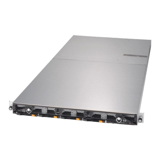
- Page 1 SuperStorageServer ® SSG-6019P-ACR12L USER’S MANUAL Revision 1.0b...
- Page 2 State of California, USA. The State of California, County of Santa Clara shall be the exclusive venue for the resolution of any such disputes. Supermicro's total liability for all claims will not exceed the price paid for the hardware product.
- Page 3 If you have any questions, please contact our support team at: support@supermicro.com This manual may be periodically updated without notice. Please check the Supermicro website for possible updates to the manual revision level. Warnings Special attention should be given to the following symbols used in this manual.
-
Page 4: Table Of Contents
Preface Contents Chapter 1 Introduction 1.1 Overview ..........................8 1.2 Unpacking the System ......................8 1.3 System Features ........................9 1.4 Server Chassis Features ....................10 Control Panel ........................10 Front Features ........................11 Chassis Rear ........................11 1.5 Motherboard Layout ......................12 Quick Reference Table ......................13 Chapter 2 Server Installation 2.1 Overview ..........................16 2.2 Preparing for Setup ......................16 Choosing a Setup Location ....................16... - Page 5 SuperStorageServer SSG-6019P-ACR12L User's Manual Installing the Processor Heatsink Module (PHM) ............31 Removing the Processor Heatsink Module from the Motherboard .......32 Memory Installation ......................33 ESD Precautions .......................33 Precautions ........................33 Introduction to Intel® Optane DC Persistent Memory ............33 Memory Support ......................33 Memory Installation Sequence ..................34 General Memory Population Requirements ..............35...
- Page 6 Preface 4.4 Jumpers ..........................59 Explanation of Jumpers ....................59 4.5 LED Indicators ........................62 Chapter 5 Software 5.1 Microsoft Windows OS Installation ..................64 5.2 Driver Installation ........................66 5.3 SuperDoctor 5 ........................67 ® 5.4 IPMI ............................67 Chapter 6 UEFI BIOS 6.1 Introduction .........................68 6.2 Main Setup .........................69 6.3 Advanced Setup Configurations ..................70 6.4 Event Logs ..........................97...
- Page 7 SuperStorageServer SSG-6019P-ACR12L User's Manual Contacting Supermicro Headquarters Address: Super Micro Computer, Inc. 980 Rock Ave. San Jose, CA 95131 U.S.A. Tel: +1 (408) 503-8000 Fax: +1 (408) 503-8008 Email: marketing@supermicro.com (General Information) support@supermicro.com (Technical Support) Website: www.supermicro.com Europe Address: Super Micro Computer B.V.
-
Page 8: Overview
SuperStorageServer SSG-6019P-ACR12L User's Manual Chapter 1 Introduction 1.1 Overview This chapter provides a brief outline of the functions and features of the SSG-6019P-ACR12L. The SSG-6019P-ACR12L is based on the X11DDW-NT motherboard and the SC802TS-R606WBP chassis. In addition to the motherboard and chassis, several important parts that are included with the system are listed below. -
Page 9: System Features
Chapter 1: Introduction 1.3 System Features The following table provides you with an overview of the main features of the SSG-6019P-ACR12L. Please refer to Appendix C for additional specifications. System Features Motherboard X11DDW-NT Chassis SC802TS-R606WBP Intel® Xeon® 81xx/61xx/51xx/41xx/31xx or 82xx/62xx/52xx/42xx/32xx series processor Socket Type Socket P (LGA 3647) Memory... -
Page 10: Server Chassis Features
SuperStorageServer SSG-6019P-ACR12L User's Manual 1.4 Server Chassis Features Control Panel There are two buttons located on the front of the chassis: a power on/off button and a UID button. In addition there are five LEDs. The locations of these buttons and LEDs on the control panel are described below. -
Page 11: Front Features
Chapter 1: Introduction Front Features The SC802TS-R606WBP is a 1U chassis See the illustration below for the features included on the front of the chassis. Figure 1-2. Front Chassis View Front Chassis Features Item Feature Description Control Panel Control panel (see previous page for details) Loosen the two thumb screws on the front of the chassis to unlock the levers on both sides, then rotate counter clockwise to unlock, clockwise Locking Levers... -
Page 12: Motherboard Layout
SuperStorageServer SSG-6019P-ACR12L User's Manual 1.5 Motherboard Layout Below is a layout of the X11DDW-NT with jumper, connector and LED locations shown. See the table on the following page for descriptions. For detailed descriptions, pinout information and jumper settings, refer to Chapter 4. -
Page 13: Quick Reference Table
(I-)SATA0~3, 4~7 I- SATA 3.0 connectors supported by the Intel PCH (S-)SATA0~3 S-SATA 3.0 connectors supported by the Intel SCU S-SATA connectors with built-in power pins and support of Supermicro SuperDOM (Disk-on (S-)SATA4/S-SATA5 Module) devices SXB1 PCI-E 3.0 (x16 + x16) Left Riser Card slot supported by CPU1 and CPU2... - Page 14 SuperStorageServer SSG-6019P-ACR12L User's Manual Connector Description SXB2 PCI-E 3.0 x16 Right Riser Card slot supported by CPU2 T-SGPIO3 Serial General Purpose I/O port USB0/1 Back panel USB 3.0 ports USB2/3 Back panel USB 3.0 ports USB4/5 USB 3.0 headers Back panel VGA port...
- Page 15 Chapter 1: Introduction VCCP0 12v VCCP1 12v #F-0 #M-0 VR13 VR13 #E-0 #L-0 5+1 PHASE 5+1 PHASE #D-0 #K-0 #C-0 145W #J-0 145W 10.4/11.2G #B-0 #H-0 #A-0 #G-0 VCCP0-(F) VCCP1 SNB CORE SNB CORE DDR-IV DDR-IV PECI : 30 PECI : 31 SOCKET ID : 0 SOCKET ID : 1 DMI3...
-
Page 16: Chapter 2 Server Installation
SuperStorageServer SSG-6019P-ACR12L User's Manual Chapter 2 Server Installation 2.1 Overview This chapter provides advice and instructions for mounting your system in a server rack. If your system is not already fully integrated with processors, system memory etc., refer to Chapter 4 for details on installing those specific components. -
Page 17: Rack Precautions
Chapter 2: Server Installation Rack Precautions • Ensure that the leveling jacks on the bottom of the rack are extended to the floor so that the full weight of the rack rests on them. • In single rack installations, stabilizers should be attached to the rack. In multiple rack in- stallations, the racks should be coupled together. -
Page 18: Mechanical Loading
SuperStorageServer SSG-6019P-ACR12L User's Manual Mechanical Loading Equipment should be mounted into a rack so that a hazardous condition does not arise due to uneven mechanical loading. Circuit Overloading Consideration should be given to the connection of the equipment to the power supply circuitry and the effect that any possible overloading of circuits might have on overcurrent protection and power supply wiring. -
Page 19: Installing The Chassis
Chapter 2: Server Installation 2.3 Installing the Chassis This section provides information on installing the chassis into a rack unit with the rails provided. The Toolless Rail System The SC802 chassis uses a toolless rail system that does not need -- as the name implies -- any hand tool to mount the rails and chassis into the server rack. - Page 20 SuperStorageServer SSG-6019P-ACR12L User's Manual Insert the top hook first, push it downwards to allow its hook to rest and engage the selected mounting hole. When the top hook is rested and engaged into place, push the bottom lock into the lower hole until it clicks and snaps into place Insert until bottom lock snaps into place.
- Page 21 Chapter 2: Server Installation Slide rail mounted equipment is not to be used as a shelf or a work space. The illustration below shows both the left and right rails mounted on a rack, ready to accept the server chassis. Right Rail Left Rail Figure 2-3.
-
Page 22: Sliding The Chassis Onto The Rack Rails
SuperStorageServer SSG-6019P-ACR12L User's Manual Sliding the Chassis onto the Rack Rails Installing the Chassis into a Rack 1. Align the chassis rails with the front of the rack rails. 2. Slide the chassis rails into the rack rails, letting it rest on to the inner rail lips, while keeping the pressure even on both sides. - Page 23 Chapter 2: Server Installation The chassis can then be secured to the rack by two thumb screws located on the left and right of the front side of the chassis. Figure 2-5. Securing the Chassis to the Rack Removing the Rails Removing a rail is basically just the reverse of the installation procedure.
-
Page 24: Chapter 3 Maintenance And Component Installation
SuperStorageServer SSG-6019P-ACR12L User's Manual Chapter 3 Maintenance and Component Installation This chapter provides instructions on installing and replacing main system components. To prevent compatibility issues, only use components that match the specifications and/or part numbers given. Installation or replacement of most components require that power first be removed from the system. -
Page 25: Accessing The System
Chapter 3: Maintenance and Component Installation 3.2 Accessing the System The system is fully accessible by loosening the two front thumbscrews and pulling out the drive drawer completely. Lever Loosen Thumbscrews Lever then pull out levers Pull Out Figure 3-1. Removing the Chassis Cover Removing a Chassis Cover 1. -
Page 26: Motherboard Components
Check that the plastic socket dust cover is in place and none of the socket pins are bent— otherwise, contact your retailer. • Refer to the Supermicro website for updates on CPU support. • Graphics in this manual are for illustration. Your components may look slightly different. -
Page 27: Assembling The Processor Package
Chapter 3: Maintenance and Component Installation Assembling the Processor Package Attach the processor to the thin processor clip to create the processor package. 1. On the top corner of the CPU, locate pin 1 (A), marked by a triangle. Also, locate notch B and notch C (and notch D for F models) on the CPU as shown below. - Page 28 SuperStorageServer SSG-6019P-ACR12L User's Manual CPU (Upside Down) Align Notch D of the CPU w/CPU LGA Lands up and Notch D of the Processor Clip Align Notch C of the CPU Pin 1 and Notch C of the Processor Clip Align Notch B of the CPU...
- Page 29 Chapter 3: Maintenance and Component Installation After creating the processor package assembly, mount it onto the heatsink to create the processor heatsink module (PHM). 1. On the heatsink label, locate "1" and the corner next to it. Turn the heatsink upside down with the thermal grease side facing up, keeping track of the "1"...
-
Page 30: Removing The Dust Cover From The Cpu Socket
SuperStorageServer SSG-6019P-ACR12L User's Manual Removing the Dust Cover from the CPU Socket Remove the dust cover from the CPU socket, exposing the socket pins as shown below. Caution: Do not touch the socket pins. Dust Cover Remove the dust cover from the CPU socket. -
Page 31: Installing The Processor Heatsink Module (Phm)
Chapter 3: Maintenance and Component Installation Installing the Processor Heatsink Module (PHM) 1. Locate the triangle (pin 1) on the CPU socket. Also locate the pin 1 corner of the PHM that is closest to "1" on the heatsink label. To confirm, look at the underside of the PHM and note the hollow triangle in the processor clip and printed triangle on the CPU located next to a screw at the corner. -
Page 32: Removing The Processor Heatsink Module From The Motherboard
SuperStorageServer SSG-6019P-ACR12L User's Manual Removing the Processor Heatsink Module from the Motherboard Before removing the processor heatsink module (PHM), power down as described in Section 3.1. 1. Using a T30 Torx-bit screwdriver, loosen and remove the screws on the PHM from the socket, starting with the screw marked #4, in the sequence of 4, 3, 2, 1. -
Page 33: Memory Installation
Populating these DIMM modules with a pair of memory modules of the same type and size will result in interleaved memory, which will improve memory performance. Note: 2933 MHz memory is supported by the 82xx/62xx series processors only. Check the Supermicro website for possible updates to memory support. -
Page 34: Memory Installation Sequence
SuperStorageServer SSG-6019P-ACR12L User's Manual DDR4 Memory Support for 81xx/61xx/51xx/41xx/31xx Processors Speed (MT/s) Ranks DIMM Capacity (GB) One Slot Two Slots per Channel per Channel DIMM Type One DIMM One DIMM Two DIMMs DRAM Density Data per Channel per Channel per Channel... -
Page 35: General Memory Population Requirements
Chapter 3: Maintenance and Component Installation General Memory Population Requirements 1. Be sure to use the memory modules of the same type and speed on the motherboard. Mixing of memory modules of different types and speeds is not allowed. 2. Using unbalanced memory topology such as populating two DIMMs in one channel while populating one DIMM in another channel on the same motherboard will result in reduced memory performance. -
Page 36: X11Dp Motherboards With 12 Dimm Slots
Please install your processors starting with CPU Socket 1. Warning: In dual-CPU configurations, memory must be installed in the DIMM slots associated with the installed CPUs. Note: Visit the product page on the Supermicro website for possible updates to memory support (www.supermicro.com). -
Page 37: Dimm Installation
Chapter 3: Maintenance and Component Installation DIMM Installation JUIDB1 USB2/3 (3.0) 1. Follow the instructions given in the LAN2 LAN1 IPMI_LAN USB0/1(3.0) JM2_1 10G PHY memory population guidelines listed in C620 JSTBY1 the previous sections to install memory S-SATA 0~3 I-SATA 0~3 I-SATA 4~7 JBT1... -
Page 38: Pci Expansion Card Installation
SuperStorageServer SSG-6019P-ACR12L User's Manual PCI Expansion Card Installation The chassis supports two full height and one low profile PCI-E expansion cards. Installing an Expansion Card 1. Power down the system as described in Section 3.1 and remove the rear cover. -
Page 39: Sas Backplane Information
Chapter 3: Maintenance and Component Installation SAS Backplane Information The SSG-6019P-ACR12L comes with three backplanes for four 3.5" SATA3 or SAS3 HDD drives (BPN-SAS3-802A or BPN-SAS3-802A-1). These backplanes have their own two LED indicators for activity and status as shown in the figure and table below. Note: Two of the four LEDs on the backplanes are currently not used for this server and are not active. -
Page 40: Motherboard Battery
SuperStorageServer SSG-6019P-ACR12L User's Manual Motherboard Battery The motherboard uses non-volatile memory to retain system information when system power is removed. This memory is powered by a lithium battery residing on the motherboard. Replacing the Battery Begin by removing power from the system as described in section 3.1. -
Page 41: Chassis Components
Chapter 3: Maintenance and Component Installation 3.4 Chassis Components Storage Drives The SC802TS chassis supports 12 3.5" storage drives in toolless drive carriers to simplify their removal from the chassis. These carriers also help promote proper airflow. The drives rest on metal brackets that runs the full width of the chassis. They attach to the system by means of three small, horizontal backplanes that supports four 3.5"... - Page 42 SuperStorageServer SSG-6019P-ACR12L User's Manual Backplanes Latch Pull handle 3.5" HDD Figure 3-7. Adding and Replacing Hard Drives...
-
Page 43: Drive Carrier Indicators
Blinking at 1 Hz Attention state—do not remove NVMe device (not supported in VMD mode) Note: Enterprise level hard disk drives are recommended for use in Supermicro chassis and servers. For information on recommended HDDs, visit the Supermicro website at https://www. -
Page 44: Checking The Temperature Of An Nvme Drive
SuperStorageServer SSG-6019P-ACR12L User's Manual Figure 3-4. IPMI Screenshot Replacing the Drive 1. Insert the replacement drive. 2. IPMI > Server Health > NVMe SSD 3. Select Device, Group and slot and click Insert. The drive Status LED indicator flashes red, then turns off. The Activity LED turns blue. -
Page 45: System Fans
Chapter 3: Maintenance and Component Installation System Fans Six fans provide cooling for the chassis. Figure 3-8. System Fans (lifted out from chassis) Replacing a System Fan 1. If necessary, open the top rear cover of the chassis while the system is running to locate the position of the failed fan. -
Page 46: Checking The Server Air Flow
Overheat Temperature Setting Some backplanes allow the overheat temperature to be set at 45, 50, or 55 by changing a jumper setting. For more information, consult the backplane user manual at www.supermicro. com. (Click Support, then the Manuals link.) Responses If the server overheats: 1. -
Page 47: Power Supply
Failed power supplies should be replaced as soon as convenient. The power supply modules are hot-swappable, meaning they can be changed without powering down the system. New units can be ordered directly from Supermicro or authorized distributors. These power supplies are auto-switching capable. This feature enables them to automatically sense the input voltage and operate at a 100-120v or 180-240v as needed by the system. -
Page 48: Power Supply Leds
SuperStorageServer SSG-6019P-ACR12L User's Manual Power Supply LEDs On the rear of the power supply module, an LED displays the status. • Solid Green: When illuminated, indicates that the power supply is on. • Solid Amber: When illuminated, indicates the power supply is plugged in and turned off, or the system is off but in an abnormal state. -
Page 49: Chapter 4 Motherboard Connections
Chapter 4: Motherboard Connections Chapter 4 Motherboard Connections This section describes the connections on the motherboard and provides pinout definitions. Note that depending on how the system is configured, not all connections are required. The LEDs on the motherboard are also described here. A serverboard layout indicating component locations may be found in Chapter 1. -
Page 50: Headers And Connectors
SuperStorageServer SSG-6019P-ACR12L User's Manual 12V 8-pin CPU Power Connectors JPWR1 and JPWR2 are the 8-pin 12V DC power input for the CPU or alternative single power source for a special enclosure when the 24-pin ATX power is not in use. Refer to the table below for pin definitions. - Page 51 Chapter 4: Motherboard Connections RAID Key Header A RAID Key header is located at JRK1 on the motherboard. The RAID key is used to support onboard S-SATA connections. Intel RAID Key Pin Definitions Pins Definition PU 3.3V Stdby PCH RAID KEY SGPIO Header The T-SGPIO3 (Serial General Purpose Input/Output) header is used to communicate with the enclosure management chip on the back panel.
- Page 52 NVMe I C Header Connector JNVI C1 and JNVI C2 are a management headers for the Supermicro AOC NVMe PCI-E peripheral cards. Please connect the I C cables to these connectors. NVMe Slots Use the four NVMe slots (P1_NVME0, P1_NVEM1, P2_NVEM0, and P2_NVME1) to attach high-speed PCI-E storage devices.
-
Page 53: Control Panel
(S-SATA0~3, S-SATA4, S-SATA5). These SATA ports are supported by the Intel C622 chipset. S-SATA4/S-SATA5 can be used with Supermicro SuperDOMs which are yellow SATA DOM connectors with power pins built in, and do not require external power cables. Supermicro SuperDOMs are backward-compatible with regular SATA HDDs or SATA DOMs that need external power cables. - Page 54 SuperStorageServer SSG-6019P-ACR12L User's Manual Power Button Ground Reset Button Ground Power Fail LED 3.3V UID LED OH/PWR Fail/Fan Fail LED 3.3V Stby NIC2 Active LED 3.3V Stby NIC1 Active LED 3.3V Stby HDD LED 3.3V PWR LED Ground Figure 4-1. JF1: Control Panel Pins Power Button The Power Button connection is located on pins 1 and 2 of JF1.
- Page 55 Chapter 4: Motherboard Connections Power Fail LED The Power Fail LED connection is located on pins 5 and 6 of JF1. Refer to the table below for pin definitions. Power Fail LED Pin Definitions (JF1) Pins Definition 3.3V PWR Supply Fail OH/Fan Fail/PWR Fail/UID LED Connect an LED cable to pins 7 and 8 of the Front Control Panel (JF1) to use UID/Overheat/ Fan Fail/Power Fail LED connections.
-
Page 56: Ports
SuperStorageServer SSG-6019P-ACR12L User's Manual Power LED The Power LED connection is located on pins 15 and 16 of JF1. Refer to the table below for pin definitions. Power LED Pin Definitions (JF1) Pins Definition 3.3V PWR LED NMI Button The non-maskable interrupt (NMI) button header is located on pins 19 and 20 of JF1. Refer to the table below for pin definitions. -
Page 57: Ethernet Ports
LED. The UID Indicator provides easy identification of a system unit that may be in need of service. Note: UID can also be triggered via IPMI on the motherboard. For more information on IPMI, please refer to the IPMI User's Guide posted on our website at http://www.supermicro.com. UID Switch Pin Definitions... - Page 58 SuperStorageServer SSG-6019P-ACR12L User's Manual Universal Serial Bus (USB) Ports There are four USB 3.0 ports (USB0/1/2/3) located on the I/O back panel. In addition, there is one USB 3.0 header (USB4/5) on the motherboard to provide front access USB connection.
-
Page 59: Jumpers
Chapter 4: Motherboard Connections 4.4 Jumpers Explanation of Jumpers To modify the operation of the motherboard, jumpers are used to choose between optional settings. Jumpers create shorts between two pins to change the function associated with it. Pin 1 is identified with a square solder pad on the printed circuit board. See the motherboard layout page for jumper locations. - Page 60 SuperStorageServer SSG-6019P-ACR12L User's Manual VGA Enable/Disable JPG1 allows you to enable or disable the VGA port using the onboard graphics controller. The default setting is Enabled. VGA Enable/Disable Jumper Settings Jumper Setting Definition Pins 1-2 Enabled Pins 2-3 Disabled LAN1/2 Enable/Disable Change the setting of jumper JPL1 to enable or disable the LAN1 and LAN2 Ethernets ports..
- Page 61 Chapter 4: Motherboard Connections C Bus for VRM Jumpers JVRM1 and JVRM2 allow the BMC or the PCH to access CPU and memory VRM controllers. See the table below for jumper settings. Jumper Settings Jumper Setting Definition Pins 1-2 BMC (Normal) Pins 2-3 Management Engine (ME) Recovery Use jumper JPME1 to select ME Firmware Recovery mode, which will limit resource...
-
Page 62: Led Indicators
SuperStorageServer SSG-6019P-ACR12L User's Manual 4.5 LED Indicators IPMI LAN LEDs A dedicated IPMI LAN, located on the back panel, has two LED indicators. The amber LED on the right of the IPMI LAN port indicates activity, while the LED on the left indicates the speed of the connection. - Page 63 Chapter 4: Motherboard Connections Unit ID LED A rear UID LED indicator at LE1 is located near the UID switch on the back panel. This UID indicator provides easy identification of a system.unit that may need service. UID LED LED Indicator LED Color Definition Blue: On...
-
Page 64: Chapter 5 Software
USB/SATA DVD drive, or a USB flash drive, or the IPMI KVM console. 2. Retrieve the proper RST/RSTe driver. Go to the Supermicro web page for your motherboard and click on "Download the Latest Drivers and Utilities", select the proper driver, and copy it to a USB flash drive. - Page 65 Chapter 5: Software 4. During Windows Setup, continue to the dialog where you select the drives on which to install Windows. If the disk you want to use is not listed, click on “Load driver” link at the bottom left corner. Figure 5-2.
-
Page 66: Driver Installation
The Supermicro website contains drivers and utilities for your system at https://www. supermicro.com/wftp/driver. Some of these must be installed, such as the chipset driver. After accessing the website, go into the CDR_Images (in the parent directory of the above link) and locate the ISO file for your motherboard. Download this file to to a USB flash drive or a DVD. -
Page 67: Superdoctor ® 5
5.3 SuperDoctor ® The Supermicro SuperDoctor 5 is a program that functions in a command-line or web-based interface for Windows and Linux operating systems. The program monitors such system health information as CPU temperature, system voltages, system power consumption, fan speed, and provides alerts via email or Simple Network Management Protocol (SNMP). -
Page 68: Chapter 6 Uefi Bios
SuperStorageServer SSG-6019P-ACR12L User's Manual Chapter 6 UEFI BIOS 6.1 Introduction This chapter describes the AMIBIOS™ Setup utility for the X11DDW-NT motherboard. The BIOS is stored on a chip and can be easily upgraded using a flash program. Note: Due to periodic changes to the BIOS, some settings may have been added or deleted and might not yet be recorded in this manual. -
Page 69: Main Setup
Note: The time is in the 24-hour format. For example, 5:30 P.M. appears as 17:30:00. The date's default value is 01/01/2015 after RTC reset. Supermicro X11DDW-L BIOS Version This item displays the version of the BIOS ROM used in the system. -
Page 70: Advanced Setup Configurations
SuperStorageServer SSG-6019P-ACR12L User's Manual 6.3 Advanced Setup Configurations Use the arrow keys to select Boot Setup and press <Enter> to access the submenu items. Warning: Take caution when changing the Advanced settings. An incorrect value, a very high DRAM frequency, or an incorrect DRAM timing setting may make the system unstable. When this occurs, revert to the default to the manufacture default settings. - Page 71 Chapter 6: UEFI BIOS INT19 (Interrupt 19) Trap Response Interrupt 19 is the software interrupt that handles the boot disk function. When this item is set to Immediate, the ROM BIOS of the host adaptors will "capture" Interrupt 19 at bootup immediately and allow the drives that are attached to these host adaptors to function as bootable disks.
- Page 72 SuperStorageServer SSG-6019P-ACR12L User's Manual Throttle on Power Fail Use this feature to decrease system power by throttling CPU frequency when one power supply has failed. The options are Disabled and Enabled. CPU Configuration Processor Configuration The following CPU information will display: •...
- Page 73 Chapter 6: UEFI BIOS Intel Virtualization Technology Use feature to enable the Vanderpool Technology. This technology allows the system to run several operating systems simultaneously. The options are Disable and Enable. PPIN Control Select Unlock/Enable to use the Protected-Processor Inventory Number (PPIN) in the system. The options are Unlock/Disable and Unlock/EnablE Hardware Prefetcher (Available when supported by the CPU) If set to Enabled, the hardware prefetcher will prefetch streams of data and instructions from...
- Page 74 SuperStorageServer SSG-6019P-ACR12L User's Manual Advanced Power Management Configuration CPU P State Control This feature allows the user to configure the following CPU power settings Speedstep (Pstates) Intel SpeedStep Technology allows the system to automatically adjust processor voltage and core frequency to reduce power consumption and heat dissipation. The options are Disabled and Enabled.
- Page 75 Chapter 6: UEFI BIOS Enhanced Halt State (C1E) Select Enabled to use Enhanced Halt-State technology, which will significantly reduce the CPU's power consumption by reducing the CPU's clock cycle and voltage during a Halt-state. The options are Disable and Enable. Package C State Control Package C State This feature allows the user to set the limit on the C State package register.
- Page 76 SuperStorageServer SSG-6019P-ACR12L User's Manual Degrade Precedence Use this feature to set degrade precedence when system settings are in conflict. Select Topology Precedence to degrade Features. Select Feature Precedence to degrade Topology. The options are Topology Precedence and Feature Precedence. Link L0p Enable Select Enable for Link L0p support.
- Page 77 Chapter 6: UEFI BIOS tCCD_L Relaxation If this feature is set to Enable, SPD (Serial Presence Detect) will override tCCD_L ("Col- umn to Column Delay-Long", or “Command to Command Delay-Long” on the column side.) If this feature is set to Disable, tCCD_L will be enforced based on the memory frequency.
- Page 78 SuperStorageServer SSG-6019P-ACR12L User's Manual SDDC Plus One Single Device Data Correction (SDDC) organizes data in a single bundle (x4/x8 DRAM). If any or all the bits become corrupted, corrections occur. The x4 condition is corrected on all cases. The x8 condition is corrected only if the system is in Lockstep Mode. The options are Disable and Enable.
- Page 79 Chapter 6: UEFI BIOS IOU2 (II0 PCIe Br3) This item configures the PCI-E port Bifuraction setting for a PCI-E port specified by the user. The options are x4x4x4x4, x4x4x8, x8x4x4, x8x8, x16, and Auto. MCP0 (II0 PCIe Br4) This item configures the PCI-E port Bifuraction setting for a PCI-E port specified by the user.
- Page 80 SuperStorageServer SSG-6019P-ACR12L User's Manual MCP1 (II0 PCIe Br5) This item configures the PCI-E port Bifuraction setting for a PCI-E port specified by the user. The options are x4x4x4x4, x4x4x8, x8x4x4, x8x8, x16, and Auto. CPU2 PcieBr1D00F0 - Port 1A/PcieBr1D01F0 - Port 1B/RSC-R1UW-2E16...
- Page 81 Chapter 6: UEFI BIOS Interrupt Remapping Select Enable for Interrupt Remapping support to enhance system performance. The options are Enable and Disable. PassThrough DMA Use this feature to allow devices such as network cards to access the system memory without using a processor. Select Enable to use the Non-Isoch VT_D Engine Pass Through Direct Memory Access (DMA) support.
- Page 82 SuperStorageServer SSG-6019P-ACR12L User's Manual VMD Config for PStack1 Intel® VMD for Volume Management Device Select Enable to use the Intel Volume Management Device Technology for this stack. The options are Disable and Enable. *If the item "Intel VMD for Volume Management Device" above is set to Enable,...
- Page 83 Chapter 6: UEFI BIOS *If the item "Intel VMD for Volume Management Device" above is set to Enable, the following items will be dislayed: VMD port 1A~VMD port 1D (Available when the device is detected by the system) Select Enable to use the Intel Volume Management Device Technology for this spe- cific root port.
- Page 84 SuperStorageServer SSG-6019P-ACR12L User's Manual Hot Plug Capable (Available when the device is detected by the system) Use this feature to enable hot plug support for PCIe root ports 3A~3D. The options are Disable and Enable. PCI-E Completion Timeout Disable Use this feature to enable PCI-E Completion Timeout support for electric tuning. The options are Yes, No, and Per-Port.
- Page 85 Chapter 6: UEFI BIOS PCH SATA Configuration When this submenu is selected, the AMI BIOS automatically detects the presence of the SATA devices that are supported by the Intel PCH chip and displays the following items: SATA Controller This item enables or disables the onboard SATA controller supported by the Intel PCH chip.
- Page 86 SuperStorageServer SSG-6019P-ACR12L User's Manual Port 0 ~ Port 7 SATA Device Type Use this item to specify if the SATA port specified by the user should be connected to a Solid State drive or a Hard Disk Drive. The options are Hard Disk Drive and Solid State Drive.
- Page 87 Chapter 6: UEFI BIOS Port 0 ~ Port 5 Spin Up Device On an edge detect from 0 to 1, set this item to allow the PCH to initialize the device. The options are Disabled and Enabled. Port 0 ~ Port 5 SATA Device Type Use this item to specify if the SATA port specified by the user should be connected to a Solid State drive or a Hard Disk Drive.
- Page 88 SuperStorageServer SSG-6019P-ACR12L User's Manual MMCFG Base Use this item to select the low base address for PCIE adapters to increase base memory. The options are 1G, 1.5G, 1.75G, 2G, 2.25G. and 3G. NVMe Firmware Source Use this item to select the NVMe firmware to support booting. The options are Vendor Defined Firmware and AMI Native Support.
- Page 89 Chapter 6: UEFI BIOS Onboard Video Option ROM Use this item to select the Onboard Video Option ROM type. The options are Disabled, Legacy, and EFI. Network Stack Configuration Network Stack Select Enabled to enable PXE (Preboot Execution Environment) or UEFI (Unified Extensible Firmware Interface) for network stack support.
- Page 90 SuperStorageServer SSG-6019P-ACR12L User's Manual Device Settings This item displays the base I/O port address and the Interrupt Request address of a serial port specified by the user. Note: This item is hidden when Serial Port 1 is set to Disabled.
- Page 91 Chapter 6: UEFI BIOS *If the item above set to Enabled, the following items will become available for user's configuration: COM2/SOL Console Redirection Settings This feature allows the user to specify how the host computer will exchange data with the client computer, which is the remote computer used by the user.
- Page 92 SuperStorageServer SSG-6019P-ACR12L User's Manual VT-UTF8 Combo Key Support Select Enabled to enable VT-UTF8 Combination Key support for ANSI/VT100 terminals. The options are Disabled and Enabled. Recorder Mode Select Enabled to capture the data displayed on a terminal and send it as text messages to a remote server.
- Page 93 Chapter 6: UEFI BIOS Terminal Type Use this feature to select the target terminal emulation type for Console Redirection. Select VT100 to use the ASCII character set. Select VT100+ to add color and function key support. Select ANSI to use the extended ASCII character set. Select VT-UTF8 to use UTF8 encoding to map Unicode characters into one or more bytes.
- Page 94 SuperStorageServer SSG-6019P-ACR12L User's Manual WHEA Support Select Enabled to support the Windows Hardware Error Architecture (WHEA) platform and provide a common infrastructure for the system to handle hardware errors within the Windows OS environment to reduce system crashes and to enhance system recovery and health monitoring.
- Page 95 Note 1: If the option for this item (TXT Support) is set to Enabled, be sure to disable EV DFX (Device Function On-Hide) support for the system to work properly. (EV DFX is under "IIO Configuration" in the "Chipset/North Bridge" submenu). Note 2: For more information on TPM, please refer to the TPM manual at http://www. supermicro.com/manuals/other.
- Page 96 SuperStorageServer SSG-6019P-ACR12L User's Manual iSCSI Configuration iSCSI Initiator Name This feature allows the user to enter the unique name of the iSCSI Initiator in IQN format. Once the name of the iSCSI Initiator is entered into the system, configure the proper settings for the following items.
-
Page 97: Event Logs
Chapter 6: UEFI BIOS 6.4 Event Logs Use this feature to configure Event Log settings. Change SMBIOS Event Log Settings Enabling/Disabling Options SMBIOS Event Log Change this item to enable or disable all features of the SMBIOS Event Logging during system boot. - Page 98 SuperStorageServer SSG-6019P-ACR12L User's Manual MECI The Multiple Event Count Increment (MECI) counter counts the number of occurences that a duplicate event must happen before the MECI counter is incremented. This is a numeric value. The default value is 1. METW The Multiple Event Time Window (METW) defines number of minutes must pass between duplicate log events before MECI is incremented.
-
Page 99: Ipmi
Chapter 6: UEFI BIOS 6.5 IPMI Use this feature to configure Intelligent Platform Management Interface (IPMI) settings. BMC Firmware Revision This item indicates the IPMI firmware revision used in your system. IPMI Status (Baseboard Management Controller) This item indicates the status of the IPMI firmware installed in your system. System Event Log ... - Page 100 SuperStorageServer SSG-6019P-ACR12L User's Manual BMC Network Configuration BMC Network Configuration Configure IPV4 support IPMI LAN Selection This item displays the IPMI LAN setting. The default setting is Failover. IPMI Network Link Status This item displays the IPMI Network Link status. The default setting is Dedicated LAN.
-
Page 101: Security
Chapter 6: UEFI BIOS This section displays configuration features for IPV6 support. LAN Channel 1 IPV6 Support Use this feature to enable IPV6 support. The options are Enabled and Disabled. Configuration Address Source This feature allows the user to select the source of the IP address for this computer. If Static is selected, you will need to know the IP address of this computer and enter it to the system manually in the field. - Page 102 SuperStorageServer SSG-6019P-ACR12L User's Manual Administrator Password Use this feature to set the administrator password which is required to enter the BIOS setup utility. The length of the password should be from 3 characters to 20 characters long. User Password Use this feature to set the user password which is required to enter the BIOS setup utility.
- Page 103 Chapter 6: UEFI BIOS Key Management This submenu allows the user to configure the following Key Management settings. Provision Factory Default Keys Select Enabled to install the default Secure-Boot keys set by the manufacturer. The op- tions are Disabled and Enabled. ...
- Page 104 SuperStorageServer SSG-6019P-ACR12L User's Manual Authorized Signatures Set New Select Yes to load the database from the manufacturer's defaults. Select No to load the DB from a file. The options are Yes and No. Append Select Yes to add the database from the manufacturer's defaults to the existing DB.
-
Page 105: Boot
Chapter 6: UEFI BIOS OsRecovery Signature This item uploads and installs an OSRecovery Signature. You may insert a factory default key or load from a file. The file formats accepted are: 1) Public Key Certificate a. EFI Signature List b. - Page 106 SuperStorageServer SSG-6019P-ACR12L User's Manual Boot Mode Select Use this feature to select the type of devices that the system is going to boot from. The options are Legacy, UEFI (Unified Extensible Firmware Interface), and Dual. Fixed Boot Order Priorities This feature prioritizes the order of a bootable device from which the system will boot. Press <Enter>...
-
Page 107: Save & Exit
Chapter 6: UEFI BIOS UEFI Application Boot Priorities This feature sets the system boot order of detected devices. • Boot Option #1 Hard Disk Drive BBS Priorities This feature sets the system boot order of detected devices. • Boot Option #1 NETWORK Drive BBS Priorities ... - Page 108 SuperStorageServer SSG-6019P-ACR12L User's Manual Save Changes and Reset After completing the system configuration changes, select this option to save the changes you have made. This will not reset (reboot) the system. Save Changes When you have completed the system configuration changes, select this option to leave the BIOS setup utility and reboot the computer for the new system configuration parameters to take effect.
-
Page 109: Appendix A Bios Codes
Appendix A: BIOS Codes Appendix A BIOS Codes A.1 BIOS Error POST (Beep) Codes During the POST (Power-On Self-Test) routines, which are performed each time the system is powered on, errors may occur. Non-fatal errors are those which, in most cases, allow the system to continue the boot-up process. - Page 110 When BIOS performs the Power On Self Test, it writes checkpoint codes to I/O port 0080h. If the computer cannot complete the boot process, a diagnostic card can be attached to the computer to read I/O port 0080h (Supermicro p/n AOC-LPC80-20). For information on AMI updates, please refer to http://www.ami.com/products/.
-
Page 111: Appendix B Standardized Warning Statements For Ac Systems
Supermicro's Technical Support department for assistance. Only certified technicians should attempt to install or configure components. Read this appendix in its entirety before installing or configuring components in the Supermicro chassis. These warnings may also be found on our website at http://www.supermicro.com/about/... - Page 112 Appendix B: Standardized Warning Statements Warnung WICHTIGE SICHERHEITSHINWEISE Dieses Warnsymbol bedeutet Gefahr. Sie befinden sich in einer Situation, die zu Verletzungen führen kann. Machen Sie sich vor der Arbeit mit Geräten mit den Gefahren elektrischer Schaltungen und den üblichen Verfahren zur Vorbeugung vor Unfällen vertraut. Suchen Sie mit der am Ende jeder Warnung angegebenen Anweisungsnummer nach der jeweiligen Übersetzung in den übersetzten Sicherheitshinweisen, die zusammen mit diesem Gerät ausgeliefert wurden.
- Page 113 SuperStorageServer SSG-6019P-ACR12L User's Manual . ٌ ا ك ً ف حالة و ٌ يك أى تتسبب ف اصابة جسذ ة ٌ هذا الزهز ع ٌ خطز !تحذ ز قبل أى تعول عىل أي هعذات،يك عىل علن بالوخاطز ال ا ٌجوة عي الذوائز...
- Page 114 Appendix B: Standardized Warning Statements Warnung Vor dem Anschließen des Systems an die Stromquelle die Installationsanweisungen lesen. ¡Advertencia! Lea las instrucciones de instalación antes de conectar el sistema a la red de alimentación. Attention Avant de brancher le système sur la source d'alimentation, consulter les directives d'installation. .יש...
- Page 115 SuperStorageServer SSG-6019P-ACR12L User's Manual Warnung Dieses Produkt ist darauf angewiesen, dass im Gebäude ein Kurzschluss- bzw. Überstromschutz installiert ist. Stellen Sie sicher, dass der Nennwert der Schutzvorrichtung nicht mehr als: 250 V, 20 A beträgt. ¡Advertencia! Este equipo utiliza el sistema de protección contra cortocircuitos (o sobrecorrientes) del edificio.
- Page 116 Appendix B: Standardized Warning Statements Power Disconnection Warning Warning! The system must be disconnected from all sources of power and the power cord removed from the power supply module(s) before accessing the chassis interior to install or remove system components. 電源切断の警告...
- Page 117 SuperStorageServer SSG-6019P-ACR12L User's Manual يجب فصم اننظاو من جميع مصادر انطاقت وإ ز انت سهك انكهرباء من وحدة امداد انطاقت قبم انىصىل إىن امنناطق انداخهيت نههيكم نتثبيج أو إ ز انت مكىناث الجهاز 경고! 시스템에 부품들을 장착하거나 제거하기 위해서는 섀시 내부에 접근하기 전에 반드시 전원...
- Page 118 Appendix B: Standardized Warning Statements Attention Il est vivement recommandé de confier l'installation, le remplacement et la maintenance de ces équipements à des personnels qualifiés et expérimentés. !אזהרה .צוות מוסמך בלבד רשאי להתקין, להחליף את הציוד או לתת שירות עבור הציוד واملدربيه...
- Page 119 SuperStorageServer SSG-6019P-ACR12L User's Manual Warnung Diese Einheit ist zur Installation in Bereichen mit beschränktem Zutritt vorgesehen. Der Zutritt zu derartigen Bereichen ist nur mit einem Spezialwerkzeug, Schloss und Schlüssel oder einer sonstigen Sicherheitsvorkehrung möglich. ¡Advertencia! Esta unidad ha sido diseñada para instalación en áreas de acceso restringido. Sólo puede obtenerse acceso a una de estas áreas mediante la utilización de una herramienta especial,...
- Page 120 Appendix B: Standardized Warning Statements Battery Handling Warning! There is the danger of explosion if the battery is replaced incorrectly. Replace the battery only with the same or equivalent type recommended by the manufacturer. Dispose of used batteries according to the manufacturer's instructions 電池の取り扱い...
- Page 121 SuperStorageServer SSG-6019P-ACR12L User's Manual هناك خطر من انفجار يف حالة اسحبذال البطارية بطريقة غري صحيحة فعليل اسحبذال البطارية فقط بنفس النىع أو ما يعادلها مام أوصث به الرشمة املصنعة جخلص من البطاريات املسحعملة وفقا لحعليامت الرشمة الصانعة 경고! 배터리가 올바르게 교체되지 않으면 폭발의 위험이 있습니다. 기존 배터리와 동일하거나 제...
- Page 122 Appendix B: Standardized Warning Statements ¡Advertencia! Puede que esta unidad tenga más de una conexión para fuentes de alimentación. Para cortar por completo el suministro de energía, deben desconectarse todas las conexiones. Attention Cette unité peut avoir plus d'une connexion d'alimentation. Pour supprimer toute tension et tout courant électrique de l'unité, toutes les connexions d'alimentation doivent être débranchées.
- Page 123 SuperStorageServer SSG-6019P-ACR12L User's Manual Backplane Voltage Warning! Hazardous voltage or energy is present on the backplane when the system is operating. Use caution when servicing. バックプレーンの電圧 システムの稼働中は危険な電圧または電力が、 バックプレーン上にかかっています。 修理する際には注意く ださい。 警告 当系统正在进行时,背板上有很危险的电压或能量,进行维修时务必小心。 警告 當系統正在進行時,背板上有危險的電壓或能量,進行維修時務必小心。 Warnung Wenn das System in Betrieb ist, treten auf der Rückwandplatine gefährliche Spannungen oder Energien auf.
- Page 124 Appendix B: Standardized Warning Statements هناك خطز مه التيار الكهزبايئ أوالطاقة املىجىدة عىل اللىحة عندما يكىن النظام يعمل كه حذ ر ا عند خدمة هذا الجهاس 경고! 시스템이 동작 중일 때 후면판 (Backplane)에는 위험한 전압이나 에너지가 발생 합니다. 서비스 작업 시 주의하십시오. Waarschuwing Een gevaarlijke spanning of energie is aanwezig op de backplane wanneer het systeem in gebruik is.
- Page 125 SuperStorageServer SSG-6019P-ACR12L User's Manual תיאום חוקי החשמל הארצי !אזהרה .התקנת הציוד חייבת להיות תואמת לחוקי החשמל המקומיים והארציים تركيب املعدات الكهربائية يجب أن ميتثل للقىاويه املحلية والىطىية املتعلقة بالكهرباء 경고! 현 지역 및 국가의 전기 규정에 따라 장비를 설치해야 합니다.
- Page 126 Appendix B: Standardized Warning Statements Attention La mise au rebut ou le recyclage de ce produit sont généralement soumis à des lois et/ou directives de respect de l'environnement. Renseignez-vous auprès de l'organisme compétent. סילוק המוצר !אזהרה .סילוק סופי של מוצר זה חייב להיות בהתאם להנחיות וחוקי המדינה التخلص...
- Page 127 SuperStorageServer SSG-6019P-ACR12L User's Manual Warnung Gefährlich Bewegende Teile. Von den bewegenden Lüfterblätter fern halten. Die Lüfter drehen sich u. U. noch, wenn die Lüfterbaugruppe aus dem Chassis genommen wird. Halten Sie Finger, Schraubendreher und andere Gegenstände von den Öffnungen des Lüftergehäuses entfernt.
- Page 128 Verbindungskabeln, Stromkabeln und/oder Adapater, die Ihre örtlichen Sicherheitsstandards einhalten. Der Gebrauch von anderen Kabeln und Adapter können Fehlfunktionen oder Feuer verursachen. Die Richtlinien untersagen das Nutzen von UL oder CAS zertifizierten Kabeln (mit UL/CSA gekennzeichnet), an Geräten oder Produkten die nicht mit Supermicro gekennzeichnet sind.
- Page 129 .قيرح وأ لطع يف ببستي دق ىرخأ تالوحمو تالباك يأ مادختسا .ميلسلا سباقلاو لصوملا مجح لبق نم ةدمتعملا تالباكلا مادختسا تادعملاو ةيئابرهكلا ةزهجألل ةمالسلا نوناق رظحيUL وأCSA ( ةمالع لمحت يتلاوUL/CSA) لبق نم ةددحملاو ةينعملا تاجتنملا ريغ ىرخأ تادعم يأ عمSupermicro.
- Page 130 사항을 준수하여 제공되거나 지정된 연결 혹은 구매 케이블, 전원 케이블 및 AC 어댑터를 사용하십시오. 다른 케이블이나 어댑터를 사용하면 오작동이나 화재가 발생할 수 있습니다. 전기 용품 안전법은 UL 또는 CSA 인증 케이블 (코드에 UL / CSA가 표시된 케이블)을 Supermicro 가 지정한 제품 이외의 전기 장치에 사용하는 것을 금지합니다. Stroomkabel en AC-Adapter...
-
Page 131: Appendix C System Specifications
Appendix C: System Specifications Appendix C System Specifications Processors Intel® Xeon® 81xx/61xx/51xx/41xx/31xx or 82xx/62xx/52xx/42xx/32xx series processor Note: Please refer to the motherboard specifications pages on our website for updates to supported processors. Chipset Intel C622 chipset BIOS 256 Mb SPI AMI BIOS® SM Flash UEFI BIOS Memory Twelve DIMM slots support up to 3 TB of ECC DDR4-2933/2666/2400/2133 MHz speed NVDIMM, RDIMM (Registered DIMM), LRDIMM (Load-Reduced DIMM) or 3DS LRDIMM memory. - Page 132 SuperStorageServer SSG-6019P-ACR12L User's Manual Regulatory Compliance Electromagnetic Emissions: FCC Class A, EN 55032 Class A, EN 61000-3-2/3-3, CISPR 32 Class A Electromagnetic Immunity: EN 55024/CISPR 24, (EN 61000-4-2, EN 61000-4-3, EN 61000-4-4, EN 61000-4-5, EN 61000-4-6, EN 61000-4-8, EN 61000-4-11), CNS14336-1, CNS13438, GB4943.1-2011, GB9254-2008(Class A) and GB17625.1-2012...
-
Page 133: Appendix D Uefi Bios Recovery
Warning: Do not upgrade the BIOS unless your system has a BIOS-related issue. Flashing the wrong BIOS can cause irreparable damage to the system. In no event shall Supermicro be liable for direct, indirect, special, incidental, or consequential damages arising from a BIOS update. - Page 134 SuperStorageServer SSG-6019P-ACR12L User's Manual The file system supported by the recovery block is FAT (including FAT12, FAT16, and FAT32) which is installed on a bootable or non-bootable USB-attached device. However, the BIOS might need several minutes to locate the SUPER.ROM file if the media size becomes too large due to the huge volumes of folders and files stored in the device.
- Page 135 Appendix D: UEFI BIOS Recovery Note: At this point, you may decide if you want to start the BIOS recovery. If you decide to proceed with BIOS recovery, follow the procedures below. 4. When the screen as shown above displays, use the arrow keys to select the item "Proceed with flash update"...
- Page 136 SuperStorageServer SSG-6019P-ACR12L User's Manual 7. Press <Del> continuously during system boot to enter the BIOS Setup utility. From the top of the tool bar, select Boot to enter the submenu. From the submenu list, select Boot Option #1 as shown below. Then, set Boot Option #1 to [UEFI AP:UEFI: Built-in EFI Shell].
- Page 137 Appendix D: UEFI BIOS Recovery 9. The screen above indicates that the BIOS update process is complete. When you see the screen above, unplug the AC power cable from the power supply, clear CMOS, and plug the AC power cable in the power supply again to power on the system. 10.
-
Page 138: Appendix E Cpu-Based Raid For Nvme
SuperStorageServer SSG-6019P-ACR12L User's Manual Appendix E CPU-Based RAID for NVMe Intel Virtual RAID on CPU (Intel VROC) is an enterprise RAID solution for NVMe SSDs ® directly attached to Intel Xeon Scalable processors. Intel Volume Management Device (VMD) is an integrated controller inside the CPU PCI-E root complex. - Page 139 Appendix E: CPU-Based RAID for NVMe Additional Information Additional information is available on the product page for the Supermicro add-on card and the linked manuals. www.supermicro.com/products/accessories/addon/AOC-VROCxxxMOD.cfm E.1 Hardware Key The Intel VROC hardware key is a license key that detects the Intel VROC SKU and activates the function accordingly.
- Page 140 SuperStorageServer SSG-6019P-ACR12L User's Manual E.2 Enabling NVMe RAID RAID for NVMe SSDs must be enabled through the UEFI BIOS. 1. Install the patch as described in the Restrictions and Requirements section on a previous page. 2. Reboot the server. 3. Press [DEL] key to enter BIOS.
- Page 141 Appendix E: CPU-Based RAID for NVMe 6. Press [F4] to save the configuration and reboot the system. 7. Press [DEL] to enter BIOS. 8. Switch to Advanced > Intel® Virtual RAID on CPU > All Intel VMD Controllers > Create RAID Volume. 9.
- Page 142 SuperStorageServer SSG-6019P-ACR12L User's Manual E.3 Status Indications An LED indicator on the drive carrier shows the RAID status of the drive. Drive Carrier Status LED Indicator Status State (red) Normal function Locating 4 Hz blink Fault Solid on Rebuilding 1 Hz Blink IBPI SFF 8489 Defined Status LED States E.4 Hot Swap Drives...
Need help?
Do you have a question about the SuperStorageServer SSG-6019P-ACR12L and is the answer not in the manual?
Questions and answers