Table of Contents
Advertisement
Quick Links
WARRANTY
EGO SYStems Inc. warrants the return policy to its original purchaser as follows; All EGO
SYS products, under normal use, will be free from faulty as long as the purchaser owns this
product.
The terms of warranty is 15 months to EGO SYS distributors considering a 3-month temporary
stock period ahead of being sold to the end user. Therefore, the actual terms of warranty is 12
months to the end user.
EGO SYS will, at its sole option, repair or replace a product, which is found to be defective. This
warranty shall be null and void if, in the sole opinion of EGO SYS, a product failure is the result of
misuse, abuse, modification, or misapplication. Except as expressly provided above, EGO SYS
products are provided 'as is' without any kind of warranty. No claim is made for merchantability or
fitness for any purpose. In no event will EGO SYS be liable for any direct, indirect, consequential, or
incidental damages arising out of use of the product. The purchaser must contact EGO SYS or its
regional representative to receive prior approval before returning a faulty unit. All such returns must
be shipped to EGO SYS' headquarters in Seoul, Korea as being packaged in the original or equivalent
protective packaging material (Rack, PCI card, Power Cables, connection cables), with freight
prepaid and adequate insurance.
If the returned product is deemed to be defective, the repaired or replacement product will be
back to you at no extra charge via the carrier chosen by EGO SYS.
T R A D E M A R K S
ESI, Waveterminal U24 and U24 are trademarks of EGO SYStems Inc. IBM is a registered trademark
of International Business Machines Corporation. Windows is a trademark of Microsoft Corporation.
Apple, Macintosh and Power Macintosh are trademarks of Apple Computer, Inc. Other product and
brand names are trademarks or registered trademarks of their respective companies.
R A D I O F R E Q U E N C Y I N T E R F E R E N C E
NOTE: This equipment has been tested and found to comply with the limits for a Class A device,
pursuant to Part 15 of the FCC Rules, and EN50 081-1/2:1992 of CE Test Specifications. This
equipment generates, uses, and can radiate radio frequency energy. If not installed and used in
accordance with the instruction, it may cause interference to radio communications.
C O R R E S P O N D E N C E
For technical support inquiries, contact your nearest Waveterminal U24 dealer or contact us directly.
Direct all other correspondence to:
EGO SYStems Inc.
Suite 1003, Shinhan Bldg. 45-11 Yoido-dong
Youngdungpo-gu, Seoul, Korea
Tel: +82 2 780-4451~3 Fax: +82 2 780-4454
Web Site:
www.egosys.net
E-mail:
webmaster@egosys.net
Second Edition July. 2002
* All features and specifications subject to change without notice.
1
Advertisement
Table of Contents

Related Manuals for ESI Waveterminal U24


Summary of Contents for ESI Waveterminal U24
- Page 1 EGO SYS. T R A D E M A R K S ESI, Waveterminal U24 and U24 are trademarks of EGO SYStems Inc. IBM is a registered trademark of International Business Machines Corporation. Windows is a trademark of Microsoft Corporation.
-
Page 2: Table Of Contents
C O N T E N T S 1. Overview______________________________________________ 3 2. Features ______________________________________________ 4 3. System Requirement ____________________________________ 5 4. Hardware Installation ___________________________________ 6 5. External Connections ___________________________________ 8 6. Driver Installation in PC________________________________ 12 1) XP ________________________________________________ 12 2) 98SE, ME, 2000 _____________________________________ 24 3) Launching MME Control Panel________________________ 29 4) Launching ASIO2.0 Control panel _____________________ 30... -
Page 3: Overview
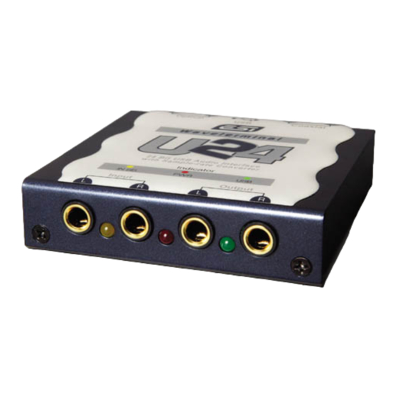
1. Overview Thank you for choosing ESI Waveterminal U24, an USB digital audio interface. Waveterminal U24 (U24) is an USB digital audio interface with 24-bit A/D, D/A for Apple Macintosh computers and IBM PC compatible system. U24 can be used with your digital audio recording software to record and playback simultaneously (full duplex) through stereo analog or stereo digital audio sources with exceptional audio quality. -
Page 4: Features
2. Features 24-bit Analog-to-Digital and Digital-to-Analog Converters Highest quality 24-bit AD/DA converters in U24 provide unmatched sound quality with exceptionally low noise. 2-In/2-Out Analog Audio Inputs and Outputs and Headphone connector U24 provides 1/4” phone jacks for use with –10dBV nominal level consumer audio equipment. -
Page 5: System Requirement
Functions as an independent Signal Converter When Digital In Clock Source is selected, U24 can be operated as an independent signal converter. In this mode, U24 is completely disconnected with the computer, but it will send out any incoming signal to both analog and digital output ports. ASIO2.0 and MME driver support You can use U24 with ASIO2.0 applications such as a Cubase, Nuendo and also MME applications such as Cakewalk, Samplitude. -
Page 6: Hardware Installation
4. Hardware Installation Before you begin, make sure you have read your computer’s manual on installing USB devices. Your computer’s manual should describe the precautions you should take. Shutting down computer wouldn’t need for installing an USB device to the computer. However, we will take it from the start to make sure you can follow every detail of installation. - Page 7 Turn on the computer. You will see “PWR” LED on U24 lights in red. U24 get the power from the computer via USB cable so you don’t need to attach any external power supplier. Series A Plug is used for those devices on which the external cable is permanently attached like Mouse, Keyboard and USB hub etc…...
-
Page 8: External Connections
5. External Connections U24 has many features that can enhance your audio production environment. If you are serious enough to about your digital audio, you may want to take time to read through this section carefully. While you may not need all of these features, and simply opt to plug in the cables to get started right away, you should at least be aware of U24’s capabilities –... - Page 9 TIP: Analog Out L can be used as Headphone connector Coaxial Out / Coaxial In USB plug In Optical Out / Optical In Rear panel of U24 Digital Input of Digital Output of external digital external digital devices CD, MD, devices CD, MD,...
- Page 10 C A B L E S & A D A P T E R S Let’s talk about the cables and connectors those can be used with U24. Analog connector U24 uses 1/4” phone connectors for analog input/output connectors. The wiring method for unbalanced connections with XLR connectors to ¼”...
- Page 11 Digital connector 1. Coaxial connector S/PDIF (IEC-958) uses 75ohm Coaxial cable and RCA connectors. U24 uses RCA connector that is the same cable as used in video transmission. Shown below is conventional RCA connector and you can use this for transmitting/receiving S/PDIF digital audio data from/to U24.
-
Page 12: Driver Installation In Pc
6. Driver Installation in PC 1) XP If the hardware installation was done properly, your computer will look for the Windows native drivers need to use U24 and start to install them. After Windows native driver was done properly, you must keep going to next exclusive U24 driver. - Page 13 2. Check ‘I accept the agreement’ and click “Install”.
- Page 14 3. Exclusive U24 driver will be installed. 4. Click “Reboot now”...
- Page 15 5. After install the software, Go to Device Manager again. It looks nothing changed. However, your Windows now recognized U24 exclusive driver.
- Page 16 6. Right mouse click and click Properties.
- Page 17 7. Click “update Driver”.
- Page 18 8. Choose “Install from a list or specific locations”. 9. Choose “Don’t search. I will choose the driver to install”.
- Page 19 10. Choose ‘Waveterminal U24’...
- Page 23 11. After rebooting your computer, open your system’s Device Manager and confirms that “Waveterminal U24” is shown under “Universal Serial Bus Controllers.” Now you’re ready to use ASIO driver software and also MME softwares with control panel.
-
Page 24: 98Se, Me, 2000
) 98SE, ME, 2000 When you install U24 driver in next step, ‘USB device’ will be disappeared. 1. Insert the provided Driver CD or diskette into the CD-Rom drive or floppy disk drive and copy all the files to a folder at your hard disk. - Page 25 2. Check ‘I accept the agreement’ and click “Install”. 3. Now, U24 driver will be installed.
- Page 26 4. Click “Reboot now” 5. In order to complete the installation and reboot again.
- Page 28 6. After rebooting your computer, open your system’s Device Manager and confirm that “Waveterminal U24” is shown under “Universal Serial Bus Controllers”.
-
Page 29: Launching Mme Control Panel
3) Launching MME Control Panel After exclusive U24 driver was done properly, click ‘U2xpanel.exe’. 'U2xpan.exe' will be appeared. * Caution: Even Two U24 control panel looks different, they have same functions and its same name. See page 33 for MME control panel functions. -
Page 30: Launching Asio2.0 Control Panel
4) Launching ASIO2.0 Control panel C U B A S E V S T After launching Cubase, Go to ‘Option’ -> ‘Audio Setup’ -> System. Select ‘‘Waveterminal U2A/U24 ASIO driver’ for the ASIO Device. -
Page 31: Control Panel Reference. Mme & Asio
5) Control Panel Reference. MME & ASIO This control panel is pretty simple. However you should be careful with ‘System performance’ in Dithering menu. In the case of U24, You have to choose the bit-rate of your recordings in ‘Recording resolution’. If your music file is 24bit recording and you're going to play it back via U24's 16bit, you can use dithering to increase quality. - Page 33 Caution: Even Two U24 control panel looks different, they have same functions and its same name. I N P U T / O U T P U T L E V E L F A D E R S 1. Level Faders Click and drag to change the input and output levels.
- Page 34 1. COAXIAL Selects the Coaxial input port (RCA type S/PDIF format) on the U24 as the digital input source. 2. OPTICAL Selects the Optical input port (Tos-link, S/PDIF format) on the U24 as the digital input source. C L O C K S O U R C E Clock Source determines that U24 will reference to.
- Page 35 A N A L O G O U T M I X E R This is where you select the source that is routed to the Analog Output jacks of U24. You can select either Analog In or Digital In for input monitoring.
- Page 36 3. USB WAVE OUT Output of wave device selected to USB Audio Device is routed to the Digital Output port for monitoring. M I X M O D E When more than one output source is selected to be played back simultaneously in the Analog or Digital Out Mixer, you are actually combining the data of two digital audio signals together, resulting in an overall gain of about 6dB/bit for each signal combined.
- Page 37 S A M P L E R A T E Sample rate determines the number of samples per second that is used to convert analog audio to digital audio. As most of you may know, sample rate for CD-DA is 44.1kHz and professional digital audio masters are usually recorded at 48kHz sample rate.
- Page 38 However, you cannot change the sampling rate of .wav file that playback through the application. If you try to convert it, it only sounds like sampling up (faster speed than normal) or sampling down (slower than normal). D I G I T A L O U T ( I E C 9 5 8 )
-
Page 39: Driver Installation In Mac
7. Driver Installation in MAC 1) Apple Sound Manager and ASIO2.0 U24 works best when using it with ASIO compatible audio software. However, you can also use it as a default Sound Manager device instead of built-in device in your Macintosh computer. There are different driver installation procedures for these two cases. - Page 40 You need to restart your Macintosh. 2. Locate the “EgoSys Waveterminal U24” file in the CD-ROM, and drag it into the “ASIO Drivers” folder of your desired application (PEAK, Logic Audio, for example).
-
Page 41: Mac Control Panel Reference
2) MAC Control Panel Reference If you use U24 as a Sound Manager device, you should use “U24 Control Panel” to modify the settings. If you use U24 as an ASIO compatible device, you should use the control panel, which can be accessed from audio applications. The exact procedure for this depends on the application you are using. - Page 42 This control panel is pretty simple. However you should be careful with ‘System performance’ in Dithering menu. You have to choose the bit-rate of your recordings in ‘Recording resolution’. If your music file is 24bit recording and you're going to play it back via U24's 16bit, you can use dithering to increase quality.
- Page 43 U S B W A V E S E L E C T Select the input source type for audio recording. 1. ANALOG IN Selects the analog input port (-10dBV unbalanced) on the U24 as the USB wave input source. 2.
- Page 44 this mode if you are recording audio signal, playing back audio file or using Real-time Sampling Rate Converter. 2. DIGITAL IN Selects the digital audio input’s data as the clock source. Selecting this mode causes U24 functions as an independent operation status from computer.
- Page 45 output ports. Analog audio signal can be converted to digital audio data, digital audio data would be converted to analog audio signal and even digital audio data can be transferred to different connector type. A N A L O G O U T M I X E R This is where you select the source that is routed to the Analog Output...
- Page 46 2. DIGITAL IN Signal connected to Digital Input port of U24 is routed to the Digital Output port for input monitoring. 3.USB WAVE OUT Output of wave device selected to USB Audio Device is routed to the Digital Output port for monitoring. M I X M O D E When more than one output source is selected to be played back...
- Page 47 select the Soft mode or manually adjust the levels of each output source you have selected. S A M P L E R A T E Sample rate determines the number of samples per second that is used to convert analog audio to digital audio. As most of you may know, sample rate for CD-DA is 44.1kHz and professional digital audio masters are usually recorded at 48kHz sample rate.
- Page 48 up to 32kHz (11x 3). Real Time Sample Rate Converting functions only for incoming digital signal. Connect digital source to Coaxial/Optical Input port and choose desired sampling rate. Now the sampling rate of the signal you can get from digital output port is converted. However, you cannot change the sampling rate of .wav file that playback through the application.
-
Page 49: Using U24 In Pc
8. Using U24 in PC 1)Working with Applications -MME S O N A R C A K E W A L K Running Cake Walk for the first time after hardware and drivers of U24 are installed correctly, initiate “Wave Profiler” to adjust proper buffer size for the new audio device. - Page 50 W A V E L A B Start Wave Lab and open the Preferences window under Options menu. Tab the “Audio Card” and you will find the Playback/Recording device set up section. Choose “USB Audio Device” to use U24 with Wave Lab.
- Page 51 S O U N D F O R G E Open Preferences window under Options menu. You can find I/O device set up section by clicking “Wave” tab. Choose “USB Audio Device” for both Playback and Record section.
-
Page 52: Working With Applications -Asio2.0
2) Working with Applications -ASIO2.0 If you have properly installed U24 ASIO driver software, you can find U24 control panel in your applications’ audio setup menu. Just click ‘ASIO Control Panel’ or ‘Control Panel’ in your application. U24 ASIO control panel will be appearing. -Cubase... - Page 53 - Logic...
- Page 54 -Nuendo...
-
Page 55: Using U24 In Mac
2 . X 1. Choose the menu Audio > Sound Out > ASIO. 2. Choose “EgoSys Waveterminal U24” from “Driver” popup menu. 3. The clock source should be “internal” unless you need digital sync. 4. Choose the right playback sample rate and channels (refer to the Peak manual). - Page 57 3. Click the triangle button of “ASIO” to see the options. (Do not turn on “ASIO” yet.) 4. Choose “EgoSys Waveterminal U24” from “Driver” popup. Turn on “ASIO” by clicking the check box. When Logic asks to reboot Logic Audio, click “Try (Re)Launch” button.
-
Page 59: Specifications
SPECIFICATIONS 1. Input LEVEL -10dBV Unbalance : -10dBV Nominal, +6.5dBV Max 2. Output LEVEL - -10dBV Unbalance : -10dBV Nominal, +3.0dBV Max 3. Input Impedance - Unbalanced Mode 10K 4. Output Impedance - Unbalanced Mode 100 5. Analog Input Gain/Attenuation Analog 0dB ~ 18dB, 0.5dB Step Size Digital -72dB ~ 0dB, About 0.5dB Step Size...
Need help?
Do you have a question about the Waveterminal U24 and is the answer not in the manual?
Questions and answers