
Related Manuals for Toro TimeCutter SWX 4250


Summary of Contents for Toro TimeCutter SWX 4250
- Page 1 Form No. 3394-187 Rev C TimeCutter ® SWX 4250 Riding Mower Model No. 74787—Serial No. 315000001 and Up *3394-187* C Register at www.Toro.com. Original Instructions (EN)
-
Page 2: Figure 1
Other additional information, contact an Authorized Service states or federal areas may have similar laws. Dealer or Toro Customer Service and have the model This spark ignition system complies with Canadian and serial numbers of your product ready. -
Page 3: Table Of Contents
Washing the Underside of the Mower Safety ............... 4 Deck.............. 44 Safe Operating Practices........4 Storage ..............45 Toro Riding Mower Safety........6 Cleaning and Storage ........45 Slope Indicator ........... 7 Troubleshooting ............47 Safety and Instructional Decals ......8 Schematics ............. -
Page 4: Safety
Data indicates that operators, age 60 years and addition to the instructions found in the ANSI standard above, are involved in a large percentage of riding below can be found in Toro Riding Mower Safety at mower-related injuries. Operators should evaluate the end of this section. - Page 5 Towing Safety • Do not make sudden turns or rapid speed changes. • Remove or mark obstacles such as rocks, tree • Do not attach towed equipment except at the hitch limbs, etc. from the mowing area. Tall grass can point.
-
Page 6: Toro Riding Mower Safety
Use only genuine Toro replacement parts to ensure that original standards are maintained. Toro Riding Mower Safety The following list contains safety information specific to Toro products or other safety information that you must know that may not be included in the ANSI standards. •... -
Page 7: Slope Indicator
Slope Indicator g011841 Figure 3 This page may be copied for personal use. 1. The maximum slope you can safely operate the machine on is 15 degrees. Use the slope chart to determine the degree of slope of hills before operating. Do not operate this machine on a slope greater than 15 degrees. Fold along the appropriate line to match the recommended slope. -
Page 8: Safety And Instructional Decals
Safety and Instructional Decals Safety decals and instructions are easily visible to the operator and are located near any area of potential danger. Replace any decal that is damaged or lost. decal93-7009 93-7009 1. Warning—don't operate the mower with the deflector up or removed;... - Page 9 decalbatterysymbols Battery Symbols Some or all of these symbols are on your battery 1. Explosion hazard 6. Keep bystanders a safe distance from the battery. 2. No fire, open flame, or 7. Wear eye protection; smoking. explosive gases can cause blindness and other injuries 8.
- Page 10 decal131-3955 131-3955 1. On 2. Off decal131-3620 131-3620 1. Pedal position—forward 3. Pedal position—reverse 2. Pedal position—neutral decal132-6863 132-6863 decal131-3621b 131-3621 1. Crushing/dismemberment hazard of bystanders—keep bystanders away from the machine; do not activate Key Choice switch (allows mowing in reverse) with bystanders nearby.
- Page 11 decal121-0772 121-0772 1. Fast 4. Choke 2. Continuous variable setting 5. Power take-off (PTO), Blade control switch 3. Slow...
- Page 12 decal132-0870 132-0870 1. Warning—read the Operator's Manual. 3. Bodily harm hazard—no riders; look 5. Ramp tipping hazard—when loading behind you when mowing in reverse. onto a trailer, do not use dual ramps; only use a single ramp wide enough for the machine and that has an incline less than 15 degrees;...
-
Page 13: Product Overview
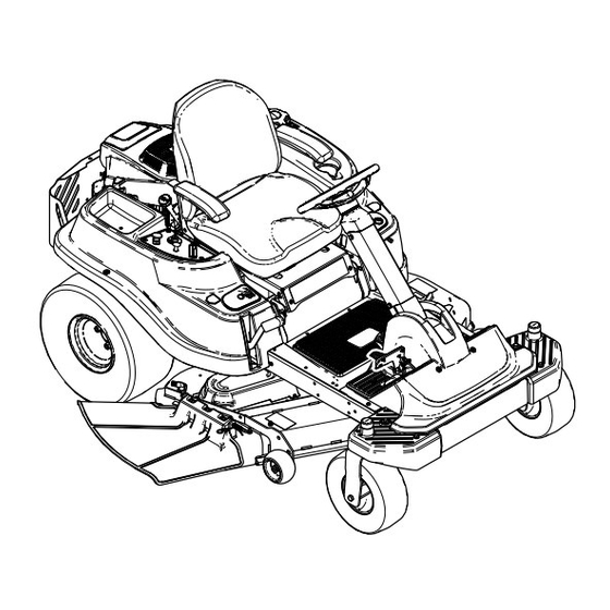
Product Overview g028247 Figure 4 1. Engine 5. Key Choice ® control 9. Anti-scalp roller 13. Rear drive wheel 2. Seat 6. Mower deck 10. Deflector 14. Control panel 3. Gas tank cap 7. Front caster wheel 11. Height-of-cut lever 4. - Page 14 Choke Control Engage the parking brake by one of the following actions: Use the choke to start a cold engine. Pull the choke • Pressing the SmartPark ™ switch to the On position knob up to engage it. Push down on the choke knob (Figure to disengage it (Figure...
-
Page 15: Operation
Operation DANGER In certain conditions during fueling, static Note: Determine the left and right sides of the electricity can be released causing a spark machine from the normal operating position. which can ignite the gasoline vapors. A fire or explosion from gasoline can burn you and Adding Fuel others and can damage property. -
Page 16: Checking The Engine-Oil Level
Add the correct amount of gas stabilizer/conditioner new, placing additional load on the engine. Allow to the gas. 40 to 50 hours of break-in time for new machines to develop full power and best performance. Note: A fuel stabilizer/conditioner is most effective when mixed with fresh gasoline. - Page 17 Understanding the Safety-Interlock System WARNING If safety-interlock switches are disconnected or damaged, the machine could operate unexpectedly causing personal injury. • Do not tamper with the interlock switches. • Check the operation of the interlock switches daily, and replace any damaged switches before operating the machine.
-
Page 18: Starting The Engine
Starting the Engine Raise from the seat. Note: The engine should remain running. Important: Do not engage the starter for more than 5 seconds at a time. Engaging the starter Return to the seat, disengage the parking brake motor for more than 5 seconds can damage the by pushing the SmartPark switch to the Off starter motor. -
Page 19: Operating The Blades
Operating the Blades Stopping the Engine Disengage the blades by pushing the The blade control switch, represented by a power blade-control switch to Off (Figure 13). take-off (PTO) symbol, engages and disengages power to the mower blades. This switch controls Move the throttle lever to the Fast position. -
Page 20: Stopping The Machine
DANGER A child or bystander could be backed over by a riding mower with blades engaged and cause serious personal injury or death. • Do not mow in reverse unless absolutely necessary. • Always look backward and down before backing up. g027750 Figure 14 •... -
Page 21: Adjusting The Height-Of-Cut
Adjusting the Height-of-Cut Note: The transport position is the highest height-of-cut position or cutting height 115 mm (4.5 inches) as shown in Figure g027751 Figure 16 Adjusting the Anti-Scalp Rollers Whenever you change the height-of-cut, adjust the height of the anti-scalp rollers. Note: Adjust the anti-scalp rollers so the rollers do not touch the ground in normal, flat mowing areas. -
Page 22: Positioning The Seat
Positioning the Seat The seat can move forward and backward. Position the seat where you have the best control of the machine and are most comfortable. g017303 Figure 19 1. Bypass-lever locations 3. Lever position for pushing the machine 2. Lever position for operating the machine g027632 Figure 18... -
Page 23: Grass Deflector
Grass Deflector Tie down the machine near the front caster wheels and the rear bumper (Figure 20). The mower has a hinged grass deflector that Note: Avoid the steering components when disperses clippings to the side and down toward the tying down the machine at the front caster turf. - Page 24 WARNING Loading a machine onto a trailer or truck increases the possibility of tip-over and could cause serious injury or death. • Use extreme caution when operating a machine on a ramp. • Use only a full-width ramp; do not use individual ramps for each side of the machine.
-
Page 25: Operating Tips
If a blade is Mowing Direction damaged or worn, replace it immediately with a genuine Toro replacement blade. Alternate the mowing direction to keep the grass standing straight. This also helps disperse clippings which enhances decomposition and fertilization. -
Page 26: Maintenance
Maintenance Note: Determine the left and right sides of the machine from the normal operating position. Recommended Maintenance Schedule(s) Maintenance Service Maintenance Procedure Interval • Change the engine oil. After the first 5 hours • Check the engine-oil level. • Clean the air intake screen. Before each use or daily •... -
Page 27: Pre-Maintenance Procedures
Pre-Maintenance Lubrication Procedures Greasing the Bearings Raising the Seat Service Interval: Every 25 hours—Grease all the lubrication points. Make sure that the parking brake is engaged, and lift Grease Type: No. 2 general-purpose, lithium-based the seat forward. grease The following components can be accessed by raising Park the machine on a level surface, and the seat: disengage the blade-control switch. -
Page 28: Engine Maintenance
Engine Maintenance Servicing the Air Cleaner Note: Service the air cleaner more frequently (every few hours) if operating conditions are extremely dusty or sandy. g027802 Figure 27 Removing the Elements Park the machine on a level surface and disengage the blade-control switch (PTO). Servicing the Foam Element Engage the parking brake, stop the engine, remove the key, and wait for all moving parts to... -
Page 29: Servicing The Engine Oil
Servicing the Engine Oil Oil Type: Detergent oil (API service SF, SG, SH, SJ, or SL) Crankcase Capacity: 2.4 L (2.5 US qt) Viscosity: See the table below. g029683 Figure 28 Checking the Engine-Oil Level Service Interval: Before each use or daily Note: Check the oil when the engine is cold. - Page 30 Disengage the PTO and ensure the parking brake is engaged. Stop the engine, remove the key, and wait for all moving parts to stop before leaving the operating position. Drain the engine oil. g027799 g029570 Figure 30...
-
Page 31: Servicing The Spark Plug
Change the engine oil filter (Figure 31). g027484 Figure 32 Servicing the Spark Plug g027477 Service Interval: Every 100 hours/Yearly (whichever Figure 31 comes first)—Check the spark plug(s). Note: Every 200 hours/Every 2 years (whichever Ensure that the oil-filter gasket touches comes first)—Replace the spark plug(s). -
Page 32: Cleaning The Cooling System
Installing the Spark Plug Tighten the spark plug(s) to 25–30 N-m (18.5–22.1 ft-lb). g027478 Figure 33 Note: Due to the deep recess around the spark plug, blowing out the cavity with compressed air is usually the most effective method for cleaning. The spark plug is most accessible when the blower housing is removed for cleaning. -
Page 33: Fuel System Maintenance
Replacing the In-Line Fuel Fuel System Filter Maintenance Service Interval: Every 100 hours/Yearly (whichever DANGER comes first)—Check the in-line fuel filter. In certain conditions, gasoline is extremely Every 200 hours/Every 2 years (whichever flammable and highly explosive. A fire or comes first)—Replace the in-line fuel filter. -
Page 34: Electrical System Maintenance
Electrical System WARNING Incorrect battery cable routing could Maintenance damage the machine and cables causing sparks. Sparks can cause the battery WARNING gasses to explode, resulting in personal injury. CALIFORNIA • Always disconnect the negative Proposition 65 Warning (black) battery cable before Battery posts, terminals, and related disconnecting the positive (red) accessories contain lead and lead... -
Page 35: Servicing The Fuses
Servicing the Fuses disconnect the charger leads from the battery posts (Figure 38). The electrical system is protected by fuses. It requires no maintenance; however, if a fuse blows, check the component/circuit for a malfunction or short. Fuse: • Main F1-30 amp, blade-type •... -
Page 36: Drive System Maintenance
Drive System Maintenance Checking the Tire Pressure Service Interval: Every 25 hours—Check tire pressure. Maintain the air pressure in the front and rear tires as specified. Uneven tire pressure can cause uneven cut. Check the pressure at the valve stem (Figure 40). -
Page 37: Mower Maintenance
If a blade is damaged or worn, replace it immediately with a Checking for Bent Blades genuine Toro replacement blade. For convenient sharpening and replacement, you may want to keep Note: The machine must be on a level surface for extra blades on hand. - Page 38 1. Blade, side previously measured to exceed 1/8 inch (3mm), the blade spindle 2. Measurement position used previously could be bent. Contact an Authorized Toro 3. Opposing side of blade being moved into measurement Dealer for service. position If the variance is within constraints, move to the next blade..
-
Page 39: Leveling The Mower Deck
Important: The curved part of the blade must be pointing upward toward the inside of the mower to ensure proper cutting. Install the curved washer (cupped side toward the blade) and the blade bolt (Figure 47). Torque the blade bolt to 35-65 ft-lb (47-88 N-m). Leveling the Mower Deck Check to ensure the mower deck is level any time you install the mower or when you see an uneven cut on... - Page 40 Check the side-to-side adjustments again. Repeat this procedure until the measurements are correct. Continue leveling the deck by checking the front-to-rear blade slope; refer to Adjusting the Front-to-Rear Blade Slope (page 40). Adjusting the Front-to-Rear Blade Slope Check the front-to-rear blade level any time you install the mower.
-
Page 41: Removing The Mower
g014634 Figure 53 1. Adjusting rod 3. Lock nut 2. Adjusting block g014635 Figure 54 To raise the front of the mower, tighten the adjustment nut. To lower the front of the mower, 1. Front support rod 3. Deck bracket loosen the adjustment nut. -
Page 42: Mower Belt Maintenance
3. Outside pulley 7. Mower deck handles 4. Spring Using a spring removal tool, (Toro part no. 92-5771), remove the idler spring from the deck hook to remove tension on the idler pulley and Route the new belt around the engine pulley and... -
Page 43: Replacing The Grass Deflector
Replacing the Grass Deflector Service Interval: Before each use or daily—Inspect the grass deflector for damage WARNING An uncovered discharge opening could allow the lawn mower to throw objects in the operator’s or bystander’s direction and result in serious injury. Also, contact with the blade could occur. -
Page 44: Cleaning
Cleaning Cleaning under the Front of the Machine Service Interval: After each use—Check and clean the front of the mower. Remove debris under the front of the machine with compressed air or by hand with a brush (Figure 59). Note: Do not use water to clean under the front of the machine, this can cause build up of debris. -
Page 45: Storage
Storage Cleaning and Storage Disengage the blade control switch, move the motion controls outward to the park position, stop the engine, and remove the key. Remove grass clippings, dirt, and grime from the external parts of the entire machine, especially the engine. - Page 46 Clean any dirt and chaff from the top of the mower. Scrape any heavy buildup of grass and dirt from the underside of the mower, then wash the mower with a garden hose. Check the condition of the drive and mower belts.
-
Page 47: Troubleshooting
Troubleshooting Problem Possible Cause Corrective Action The engine overheats. 1. The engine load is excessive. 1. Reduce ground speed. 2. The oil level in the crankcase is low. 2. Add oil to the crankcase. 3. The cooling fins and air passages 3. - Page 48 Problem Possible Cause Corrective Action There is abnormal vibration. 1. The engine mounting bolts are loose. 1. Tighten the engine mounting bolts. 2. The engine pulley, idler pulley, or blade 2. Tighten the appropriate pulley. pulley is loose. 3. The engine pulley is damaged. 3.
-
Page 49: Schematics
Schematics g027754 Electrical Diagram (Rev. A) - Page 50 Notes:...
- Page 51 Notes:...
- Page 52 Toro importer. If all other remedies fail, you may contact us at Toro Warranty Company. Australian Consumer Law: Australian customers will find details relating to the Australian Consumer Law either inside the box or at your local Toro Dealer.