Sharp XE-A303 Manual
Electronic cash register
Hide thumbs
Also See for XE-A303:
- Instruction manual (504 pages) ,
- Bedienungsanleitung (104 pages) ,
- Instruction manual (104 pages)
Advertisement
Quick Links
For quick set-up, follow the steps shown below. Note that malfunction may occur
if you do not follow the steps. For further information, please read the instruction
manual. For installing the cash register, find a stable surface near an AC outlet
where the cash register will not subject to water sources or direct sunlight.
1
Installing The Cash Register
Install the cash register using the fixing
angle bracket provided with the register.
• Thoroughly clean the location where the
fixing angle bracket (B) is to be placed.
• Peel off the adhesive tape on the fixing
angle bracket.
• Hook the angle bracket onto the hook
(A) that is located at the bottom rear
of the register.
• Firmly stick the fixing angle bracket to the
table surface that you cleaned above.
To remove the resister from the fixing
angle bracket:
• Lift up the front of the register and pull
the register towards you.
2
Initialising the Cash Register
To ensure the cash register operates properly, initialise it using the following
procedure.
• Make sure the power cord is not inserted into the AC outlet.
• Insert the manager (MA) key into the mode lock and turn it to the PGM position.
• While holding down both the
The buzzer will sound three times and "***MRS.***" will be displayed.
• The cash register has now been initialised.
The register display will show "0.00" with "PGM".
CAUTION: To charge the rechargeable batteries, keep the power on for one or two days.
Leave the register with the mode switch in a position other than
NOTE: If you press a key by mistake, an error message may be displayed. Press the
clear the message after installing paper rolls.
3
Preparing the Printer
• Lift the rear of the printer cover and detach it.
• Remove the white retainer at the position
shown at the right.
NOTE: Please keep this retainer for future
use when transferring the cash register.
• Move the print head release lever upwards
as illustrated at the right.
CL
JOURNAL
key and the
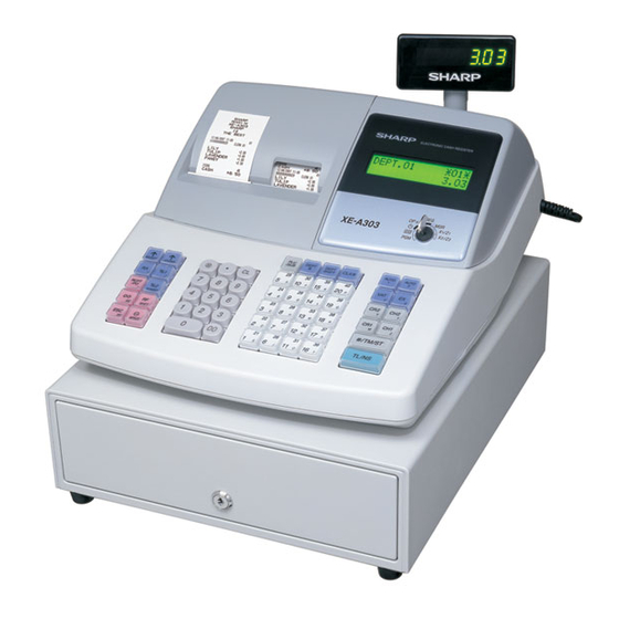
Model XE-A303
Model XE-A303
Important Notice
The cash register will
operate correctly only
after the following steps
have been carried out.
key, insert the plug into the AC outlet.
.
REG
OPX/Z
MGR
X1/Z1
X2/Z2
PGM
Mode Lock
REG
OPX/Z
MGR
X1/Z1
X2/Z2
PGM
Mode Lock
CL
key to
REG
OPX/Z
MGR
X1/Z1
X2/Z2
PGM
Mode Lock
Advertisement

Related Manuals for Sharp XE-A303


Summary of Contents for Sharp XE-A303
- Page 1 Model XE-A303 Model XE-A303 For quick set-up, follow the steps shown below. Note that malfunction may occur if you do not follow the steps. For further information, please read the instruction manual. For installing the cash register, find a stable surface near an AC outlet where the cash register will not subject to water sources or direct sunlight.
- Page 2 Installing The Paper Rolls • Cut off approximately one revolution of each paper roll. Make sure the paper end is cut as illustrated below. For receipt paper installation • Set a paper roll in the paper cradle of the receipt side (left side) as illustrated below.
- Page 3 Entering A Basic Sale OPX/Z X1/Z1 Insert the operator key into the mode lock and turn to the REG position. X2/Z2 The cash register has forty department buttons in white through which to enter your sales. The purpose of these are to assist you in analysing your business. Mode Lock (For example, department 1 could be used for food sales and department 2 for non food sales etc).
- Page 4 Reporting OPX/Z X1/Z1 The cash register has two reporting types. Use the reading function (X) when X2/Z2 you need to take a reading of sales information entered since the last reset. This reading can be taken any number of times without clearing totals. Mode Lock Use the resetting function (Z) when you need to clear the registers memory.