Table of Contents
Advertisement
Quick Links
Advertisement
Table of Contents
Troubleshooting

Related Manuals for Dover Markem-Imaje LASER 7031


Summary of Contents for Dover Markem-Imaje LASER 7031
- Page 1 Book for service engineers Internal use only...
- Page 3 Contents A70622-D1 3/192...
- Page 4 Contents Notes: A70622-D1 4/192...
-
Page 5: Table Of Contents
Contents Safety Printer Description Overview Working principle MI 7000 series Marking head 7031 HD LASER head Cabinet Dimensions Printhead Dimensions Controller Connection Electronic Compartment Operator interface Marking Features ES500 Fume extractor FS400 Cooling System Other Fume extractors Pre-Installation Installation Training Policy Installation Guide Pre-installation Form... - Page 6 Contents Safety Tunnel After Sales After sales policy Technical Claims Maintenance checklists Standard/Access/Premium Agreement Checklist for Access agreement Checklist for Standard agreement Checklist for Premium agreement Troubleshooting Troubleshooting guide Measure power for diagnosis (without the lens) Technician Spare Parts List Spare parts sheets Electronics General bloc diagram...
-
Page 7: Safety
Safety A70622-D1 7/192... - Page 8 Safety Notes: A70622-D1 8/192...
- Page 9 Safety Obligations for People involved in the Laser market Such people include manufacturers, importers, traders, suppliers, salesmen and lessors or renters. Laser appliances often conceal an unexpected and sometimes invisible danger, and any people involved in this market, it is required to inform the users of any such danger. Labelling Prior to any delivery, the supplier must ensure the appliance is correctly labelled.
- Page 10 Safety Obligations for Laser Users According to the standard EN60825 the user is required to read very carefully and then follow the set of directions supplied with the appliance, as well as the safety instructions it contains, prior to initial use of the appliance. The instructions regarding safety at work require all the companies concerned to implement all the necessary measures in respect of health and safety at work, to display them and ensure they are followed.
- Page 11 Safety Read these instructions before working on equipment Liability Markem-Imaje shall not be liable in the event of failure to comply with safety instructions or failure to observe the basic safety rules applicable to the use and maintenance of Markem- Imaje equipment.
- Page 12 Safety Applications for laser equipment The CO2 laser equipment described in this document is designed for marking material by infrared radiation in an industrial environment. The equipment is a Class IV laser product and it is therefore recommended that a laser safety officer is appointed and that the operator is advised accordingly.
- Page 13 Safety Installation The printer must be installed in a well-ventilated place away from any source of heat, flame or sparks. The printer and print head must be secured with the attachment devices provided. The printer installation on the production line must not generate any risks for people. The operator's workstation must face the printer.
- Page 14 Safety ■ Eye protection Since the CO2 laser beam is very strongly absorbed by water, the cornea and the sclerotic coat are the main parts of the eye which are at risk from damage. They can suffer irreversible defects and permanent scarring following direct or indirect exposure to a CO2 laser beam.
- Page 15 Safety ■ Skin protection Skin exposed to laser radiation may be subject to burns or cuts which can sometimes cause permanent injury. The following precautions only apply to protection against CO2 laser radiation, with wavelengths between 9.3 and 11.5 µm (microns): Do not place the hands or objects of any kind in the path of the CO2 laser beam.
- Page 16 Safety Fume and vapour hazards ■ Fume hazards The reactions produced by the laser system can lead to the emission of hazardous particulates or gases. These by-products can be toxic. Ensure that all safety instructions are observed before working on material with a laser beam. Also verify compliance with health, safety and environmental requirements.
- Page 17 Safety Electrical hazards Installation, servicing and repair work should be entrusted to Markem-Imaje-qualified people or to electrical technicians following consultation with the Markem-Imaje after-sales dept. or an authorized dealer. Disconnect the equipment from the mains power supply before carrying out any work which requires the removal or replacement of a part.
- Page 18 Safety ■ Safety shutter All MARKEM-IMAJE systems are fitted with a safety shutter operated by an electromagnet. This allows the user to block or deflect the laser beam with a reflective mechanical plate. There are two position sensors for the shutter open and closed position which are used to monitor safety.
-
Page 19: Printer Description
Printer Description A70622-D1 19/192... - Page 20 Printer Description Notes: A70622-D1 20/192...
-
Page 21: Overview
Printer description Overview Markem-Imaje 7000 range includes the following products: LASER 7031 (λ = 10.6µm) LASER 7031S (λ = 9.3µm) LASER 7031L (λ = 10.2µm) LASER 7031 HD (λ = 10.6µm) LASER 7031 HD QS (λ = 10.6µm) LASER 7031 L HD (λ = 10.2µm) LASER 7031 S HD QS(λ... -
Page 22: Working Principle
Printer description Working principle The laser beam is generated by a CO2 laser source and expanded by the beam expander, and then sent to movable mirrors. Two galvanometer-operated mirrors deflect the expanded laser beam, the mirrors steer the laser beam onto an optical lens which focuses the steered beam onto the substrate. -
Page 23: Mi 7000 Series
Printer description MI 7000 series LASER models The table below gives the different printer models available in the 7000 series with the main characteristics that distinguish them. Printer Wave QuickScan IP versions Power Ideal for models lengh version Adapted for inked paper, painted IP54 –... -
Page 24: Marking Head
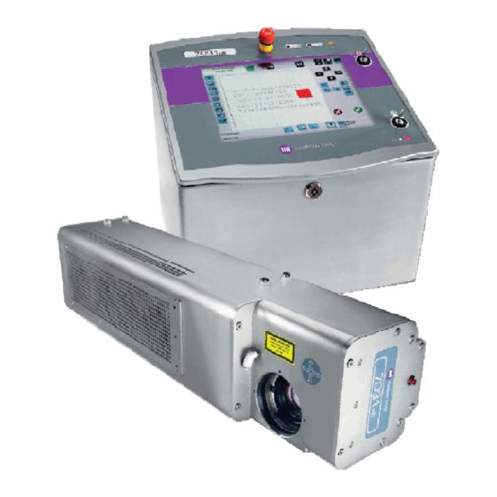
Printer description Marking head MARKEM-IMAJE 7000 series is designed with a CO LASER source placed in the marking head which is is cooled down by air fans (standard IP54 version). Two beam outputs model 0° and 90° are available. They are protected by a ring of air supplied by a pressurization air kit (0.5bar). IP65 head is cooled down by pressured air. - Page 25 Printer description Air Fans (IP54 version) CO2 LASER source Shutter assembly It is a safety part which disable the laser beam in case of failure or abnormal situation of the laser installation Beam expander It expends the beam Galvo assembly 2 Mirrors mounted on motor deflect the expanded laser beam, directing the beam in directions x...
-
Page 26: 7031 Hd Laser Head
Printer description 7031 HD LASER head 7031 HD head The “H” stands for “High” and the “D” stands for “Definition” or “Density”. This laser head allow the advantage to mark on a large print area using high quality coding. Most of the parts remain the same with standard model except : The Beam Expander expands the beam by 6 instead of 3. - Page 27 Printer description QuickScan HD head HD QuickScan head is based on the HD standard concept, possibility to print on a large marking field using high quality coding. HD QuickScan head includes : Beam expander (x6), 14mm Galvo Mirrors, A Specific Galvo bloc equipped with a faster digital 14 mm Galvo. HD QuickScan allows a faster driving of the bigger mirror than HD standard model.
- Page 28 Printer description 1/ IP65 using Air plant The IP65 head is connected to the air plant throught the air regulator. It is the standard configuration to ensure IP65 rating of the laser head. IP65 LASER head plant IP65 Air regulator The air consumption depends on both the environment temperature and the application duty.
- Page 29 Printer description 2/ IP65 using Air Cooler This type of head is dedicated to work with the FS400 cooling system. The IP65 Aircooler head have a specific design including two cylindrical tubes located into the lower part of the laser head.
- Page 30 Printer description Pointing diode option Thank to a visible beam, this option allows you to modify easily and accurately the position of the marking. This option is particularly useful whether there are different product sizes on the conveyor and the operator want to set the message easily in an accurate area. This mode active a specific laser settings which allows seeing the description of the message in red colour.
-
Page 31: Cabinet Dimensions
Printer description Cabinet Dimensions SIDE view TOP view 7031 7031S/L (IP54) 7031 7031S/L IP65 7031HD (IP54) 7031HD (IP65) 7031 HD Quickscan Printhead Dimensions 7031 7031S/L (IP54) 7031 7031S/L (IP65) A70622-D1 31/192... - Page 32 Printer description 7031HD (IP54) 7031HD (IP54) 7031HD 0° (IP54) A70622-D1 32/192...
- Page 33 Printer description 7031HD 90° (IP65) Air Plant 7031HD 0° (IP65) Air Cooler A70622-D1 33/192...
- Page 34 Printer description 7031HD 90° (IP65) Air Cooler A70622-D1 34/192...
- Page 35 Printer description 90° Bent Umbilical 90° Bent Umbilical is compatible with all Laser models. P/N are the following : ENM70771 - 6M Umbilical Laser 90 Deg bent ENM70772 - 9M Umbilical Laser 90 Deg bent Dimension of the new 90° Bended Umbilical Connector (unit = mm) Weight Controller………….under 20 Kg (44lbs) Head………………..from 14 to 16.6 Kg...
-
Page 36: Controller Connection
Printer description Controller Connection MARKEM-IMAJE 7000 series offer 4 quick connections (M12 connectors) for connecting accessories and 2 com ports for external communications. DTOP1 Alarm(Beacon) Cable glands TOP + Orange Lamp Ground +24V Not used Not used Not used TOP - Red Lamp DTOP2 Encoder (tackymeter) -
Page 37: Electronic Compartment
Printer description Electronic Compartment First level : Electronic plate See section Electronic for more details (Diagram bloc, connections..) Led Keys assembly PC mother board 5315 Touch Screen assembly Interconnect rack board assembly Industrial interface board Galvo interface ScanAlone A70622-D1 37/192... - Page 38 Printer description Second level : Power supply plate This plate provides power supply and it is located under the electronic plate. See section Electronic for more details (Diagram bloc, connections..) Galvo PSU 15V 75W AC/DC Assembly Auxiliary PSU LASER source PSU 5/12/24V 48V 600W A70622-D1...
-
Page 39: Operator Interface
Printer description Operator interface 12" color touch screen The main components of the interface are a 12" color touch screen and an interface area comprising of indicators, two keyswitches and an emergency stop button. Language available Operator interface could be used with the following languages: English French Arabic... -
Page 40: Marking Features
Printer description Marking Features Message composition The fields which compose a message are : Text field Logo field (Bmp, dxf) Shift code field Counter field Date (Post date, Custom date) Time field Operator variable field External variable field Barcode field Fonts and characters size Arial Narrow Arial Unicode MS... - Page 41 Printer description Barcodes Available barcode are : EAN-8 / EAN-13 • UPC A / UPC E • Datamatrix / QR code (planned in 2013) • 2/5 interleaved • ITF 14 • EAN 128 / Code 128 • Linear barcodes Barcode size limit up to 60mm : Limitation of the barcode size has been increased up to 60mm for all library barcodes.
- Page 42 Printer description 2D barcodes Data Matrix : Settings & Adjustments Accurate alignment: The laser head has to be perfectly perpendicular to the product otherwise the shape of data matrix will not be squared or rectangular. Good Vacuum: During the coding phase, it is important that the dust has to be vacuumed correctly.
- Page 43 Printer description Post dates Rounded post date The Rounded Date option is a new option linked to the Postdate function. When the Rounded Post Date option is activated, the postdate value will be automatically equal to the last day of the month.
- Page 44 Printer description Matrix mode The Matrix mode allows the customer to define a Mother message and to duplicate it. Mother message Note : Duplicated Message Refer to TB111206 & TB121201 for more details Typical application : DANONE Application to code on yogurts lids A70622-D1 44/192...
- Page 45 Printer description Print repeat mode The Print repeat mode will offer users the ability to print many messages from the same DTOP, In addition to the distance between two prints, the user will have the ability to indicate the number of prints. The following information should be taken in to consideration when using such a function: The number of prints to repeat (limited to 100) : if the value of “Print repeat”...
-
Page 46: Es500 Fume Extractor
Printer description ES500 Fume extractor Reference document : ES500 Instruction manual (A43808) available on planet & TB110903 “ES500 Fume extractor introduction”. ES500 Model range The ES500 is now the standard and the most technically advanced Laser Fume Extractor. Part number Part number Model Description... - Page 47 Printer description ES500 Description Fume extractor Filters Reverse Flow Filter technology and a large pre-filter capacity enhance filter performance and ensure longer filter lifetime. Two levels of filtration are provided on all ES500 Extractors. The extractor is equipped with a “Filter Change System Failure signal” : 2 failures from filters are detected and displayed by the extractor : Fume extractor pre-clogged : Pre-filter or combined filter are partially (75%) clogged...
- Page 48 Printer description > Overview of the Air Flow through Filters > Filter replacement Wh en changing filters, always wear a mask, safety glasses and gloves. Standard P/N : 10058219 Standard P/N : 10058218 PVC P/N : 10038386 PVC P/N : 10038385 A70622-D1 48/192...
- Page 49 Printer description ES500 I/O customization: The interface cable with the Laser is equipped with a M12 connector (5-pin connector (M12- male). It has the following pin assignment : Pre-clogged alarm Clogged alarm +24 V DC Remote start/stop The following table gives the connection and the setting to perform according to required working modes : Stand alone or Laser remote.
- Page 50 Printer description Fume extractor Clogged/Pre-clogged could be detected by wiring pin 3, 4 and 5 to the controller and to set I/O input (MINx) to “Fume ext warning” and “Fume ext alarm”. Internal Mode Scheme Laser settings Switch I/O input MIN1 has to be set to “Fume ext Connection to detect and warning”...
- Page 51 Printer description Installation and settings Extractor is delivered with 6 meters tube and semi rigid nozzle kits. Following recommendation should be taken into account at the installation : Place the nozzle as closer as possible to the marking area, Minimize tube length, Avoid tube bent, Do not set the air flow to the maximum.
-
Page 52: Fs400 Cooling System
Printer description FS400 Cooling System FS400 Model range FS400 Cooling System is dedicated for the IP65 Aircooler option for 7031 series HD print heads. Part number Part number Model Description (110V) (230V) FS400 FS400 COOLER A70858 A70859 FS400 Specification FS400 is a cooling filtration system which is designed to supply cool and filtered air to laser head. - Page 53 Printer description FS400 Description Unit/Filter condition display / Flow controler Filter compartment Air pump Cooling output Air inlet Power cable Signal cable (with M12 connector) Filters maintenance Replacement of the FS400 filter ( has to be done when ENM70860) detected by cooling system (Red light on control panel) FS400 filter changing interval : Standard environment = once a year Harsh environment = one (1) time every 6 months...
- Page 54 Printer description FS400 I/O customization The following table gives the connection and the setting to perform according to required working modes. Internal Mode Scheme Laser settings Switch Stand alone : Standard position standard Shunt pin-1 and pin-2 configuration position M12-1 FS400 is M12-2 powered, the...
- Page 55 Printer description Complete connection – Remote Stop/Start and Filter warning: FS400 Controller I/O Board Note : Cable between the extractor and the laser must be ordered separately (Ref A70148) Air cooler setting It is not necessary to set the air flow to the maximum level (two levels are sufficient). Installation (with IP65 HD head) The system was qualified with 9 meters hose.
- Page 56 Printer description General overview about the installation For integration, take into account the design of the IP65 laser head model. It will take an additional space of approximately 83 mm in height to the HD version head of 7000. Take in mind that you have to connect the two 75mm diameter hoses which will take additional space especially if you need to contort hose as you will be limited by its bending radius : you will need at least 140 mm.
- Page 57 Printer description Adjustments 1- Autoflow Reset (should only be performed with clean filters) Turn on the cooling system, Ensure the start signal is present with all the hose in place, Press and hold the + & - buttons until the Green and Red led’s begin to flash together.
-
Page 58: Other Fume Extractors
Printer description Other Fume extractors ES400 & ES400PVC The ES400 series have been replaced by ES500 series since november 2011. Model ES400 filters will be available through 2018. Description Part number ES400 Pre Filter ENM70356 ES400 Combined filters ENM70357 (HEPA+carbon) ES400 Description Part number... -
Page 59: Pre-Installation
Pre-Installation Installation Training A70622-D1 59/192... - Page 60 Pre-Installation Installation Training A70622-D1 60/192...
-
Page 61: Policy
Pre-Installation Installation Training Policy Pre-Installation form For each new application*, the MI proposal has to be validated by the customer through the print sample process. For each project, a Pre-installation has to be performed in order to: • Clearly define the customer need/application, •... - Page 62 Pre-Installation Installation Training Training 2 cases of operator training : 1- Basic Operator Training Course S42610 (User Training Cust Site) SAP Part Number S42611 (User Training MI site) People to train Production line operators Pre-requisites To be Markem-Imaje customer or prospect Training objectives Operate, maintain and perform basic repairs Respect safety rules linked to laser use...
- Page 63 Pre-Installation Installation Training 2- Advanced Operator Training Course S42612 (Supervisor Training Cust Site) SAP Part Number S42613 (Supervisor Training MI site) Maintenance technician People to train Maintenance manager Basic operator course Pre-requisites Maintain, fix basic faults and replace spare parts Training objectives Respect the safety rules for using a laser •...
- Page 64 Pre-Installation Installation Training Simplified Installation process Each installation and printing quality have to be validated in production mode with the customer and the “Installation certificate” has to be filled. Supply a “back-up printer configuration” card (messages, fonts, and printer setup) for the future maintenance operation with MI hot-line. MI proposal OOBCL Pre-installation...
-
Page 65: Installation Guide
Pre-Installation Installation Training Installation Guide The most important contact a company can have with the MI technical service department is the first one. Pre-installation or installations have a habit of setting the tone of how a customer views Markem-Imaje. You are the ambassador of MARKEM-IMAJE! It is expected of each service engineer to use the right tools and training we supply them with the best of their abilities in maintaining a high level of customer service and technical expertise. - Page 66 Pre-Installation Installation Training A70622-D1 66/192...
- Page 67 Pre-Installation Installation Training Step 1: Customer project validation Print samples process & Sampling activity For each MI proposal concerning a new application or new substrate, the marking has to be validated by the customer through the print sample process. Pre-installation Before making an offer it is necessary that a local service/sales engineer makes an evaluation of the application during a Pre-installation visit.
- Page 68 Pre-Installation Installation Training Step 2: Installation preparation In order to perform an efficient and professional installation, the installation has to be strongly prepared to avoid any surprise during the installation. Several points have to be checked during this preparation; Contact your sales & logistic colleagues Liaise with the sales department to check what was sold, what was ordered and the specific requirements for the installation (pre-installation form).
- Page 69 Pre-Installation Installation Training Step 3: Installation Arriving at customer site & installation : Meet your contact and confirm the plan for the installation Confirm the plan for the installation according to your last exchange with your contact • and with the information present in the Pre-installation form. Respect the safety or quality rules to follow during your stay on the customer site.
- Page 70 Pre-Installation Installation Training Starting the laser Start the Laser • Measure laser power and adjust “laser activation level” in specific technician menu to • have an output power of 30 W. Create the customer's message by using the right laser settings and according to the •...
- Page 71 Pre-Installation Installation Training For installation in Pharmaceutical market Quote the Validation Package when required in the Pharmaceutical industry and separately from the product quotation. Regulations impose to validate the installation of automated systems in pharmaceutical industry for European and American market. Validation package offers a clear &...
-
Page 72: Pre-Installation Form
Pre-Installation Installation Training Pre-installation Form General The Laser Pre-installation Form has been designed to be a guide for salesmen or Service Engineers during the pre-installation visit. This visit is strongly recommended in order to ensure efficient and professional installation. During the pre-installation visit, it is important to behave like if you have to install the machine: Position of the equipment ( laser, cabinet and extraction unit), •... - Page 73 Pre-Installation Installation Training MARKEM-IMAJE REFERENCE Date: Your Reference: Subsidiary / Distributor : Country: Salesman's name : Tel. : Service Engineer's name : Tel. : Laser Sample request Form reference : CUSTOMER REFERENCE Customer’s Name : Group : Address : Sales contact name: Tel.
- Page 74 Pre-Installation Installation Training PRODUCT DESCRIPTION Product type: Size: Substrate: MARK DESCRIPTION Mark location: On side Top side Bottom side Neck MATRIX MODE ACCESSORIES Controller support Customer table MI Extractor Specific integration 3 Lights 24V 2 Lights 24V Customer’s alarm Alarm External Signal Mounting bracket photocell Photocell...
- Page 75 Pre-Installation Installation Training EXTRACTION SYSTEM MODEL Extractor ES500 220V standard Extractor ES500 110V standard Extractor E500 220V PVC Extractor ES500 110V PVC Extractor hose extra length Ø75 mm Extractor hose line connector Note : Extractor are delivered with 6m Hose length and Ø 75 mm Default monitoring 3 wires cable + M12 connector Start and stop synchronization with laser start...
- Page 76 Pre-Installation Installation Training TUNNEL Note : A guarding tunnel must be installed on the conveyor in order to prevent from any physical access to the beam (class1 installation, refer to safety instructions). All Guarding tunnel are delivered with an interlock switch and safety labels Tunnel with door on the top Tunnel with door on the side W400 L600 H400...
-
Page 77: Sample Request Form
Pre-Installation Installation Training Sample request Form REFERENCES MARKEM-IMAJE SAMPLING DEPT. Date: Reception date: Your Reference: Reference : CUSTOMER’S REQUEST Subsidiary / Distributor : Printed sample to be addressed to Salesman ; Salesman's name : Customer’s Name : Address : Beverage Food Pharmaceuticals Cosmetics... -
Page 78: Sample Feedback Form
Pre-Installation Installation Training MESSAGE TO BE PRINTED Marking window size: Max. length available: Max . height available: Marking content: (specify character’s sizes, variable fields as date, hour, counters, …): Logos files to be supplied by Customer (.bmp, .dxf) Logos included COMMENTS Use a separate sample request per production line Join ALL TYPE (substrate, color) of samples in a shape, minimum quantity of 6 each. -
Page 79: Out Of Box Checking List
Pre-Installation Installation Training Out Of Box Checking list GENERAL INFORMATION Customer name: Subsidiary: New laser Second hand laser Service engineer Name: Serial Number: Manufacturing date: Installation date: Software version: PACKAGE CHECKING Tilt activated? Remarks Did you make a Logistic Complaint? Damaged parts / Missing parts Others In case of Logistic Problem, please refer to QAG-101... -
Page 80: Installation Safety Attestation
Pre-Installation Installation Training Installation Safety attestation Installation Safety attestation I hereby certify that I have read and acknowledged the safety rules and general conditions of use of the MARKEM-IMAJE laser, as they were mentioned on the user manual. Moreover, I certify that the MARKEM-IMAJE service engineer has performed the installation according to our requirements. - Page 81 Pre-Installation Installation Training Trial Safety Attestation I hereby certify that I have read and acknowledged the safety rules and general conditions of use of the MARKEM-IMAJE laser, as they were mentioned on the user manual. Moreover, I certify that the MARKEM-IMAJE service engineer has performed the installation according to our requirements.
-
Page 82: Power Measurement On 7000 Series
Pre-Installation Installation Training Power measurement on 7000 series Tools Required A power wizard Specifications PW-250 Range 1-250W Resolution 0.1W Wavelength range 190nm-11µm Individual calibrate wavelength 10.6µm Accuracy ±5% Target diameter Settling time (s) <4 Max. allowable input power (W) Max. target temperature (° C) Typical battery life 5 years Battery type... - Page 83 Pre-Installation Installation Training Calibrate power at installation When installing a new laser, it is necessary to calibrate power, because all the sources do not deliver exactly the same power. Switch On the laser Enter the username and password User Name: “imaje” Password: “0007ejami“...
-
Page 84: Laser Effects And Substrate Reaction
Pre-Installation Installation Training Laser effects and substrate reaction Laser beam property Laser marking is performed by two manners : Removing material from the substrate Changing the surface of the substrate. It is essential to know how the substrate absorbs the LASER beam. According to the wavelenghts and substrate properties, the absorption characteristics will be differents. - Page 85 Pre-Installation Installation Training Laser beam effects For optimum results the Laser beam has to be absorbed in the top few microns of the material surface, so that sufficient energy density is produced to modify the surface by one of the following three processes: Coating removal (Ablation) The Laser is absorbed by the surface coating and vaporizes it to reveal a contrasting substrate.
- Page 86 Pre-Installation Installation Training which reflect the beam. It is not possible to mark on bare metals But on painted or anodized metal is possible by removing the top layer (like painted caps) Note : We recommend 7031 HD Quickscan ideal to mark @ High production rate Painted caps The marking on PE, HDPE is very difficult...
- Page 87 Pre-Installation Installation Training Substrate influence The substrate has a strong influence on the marking quality, but also marking performance (maximum speed and throughput) Laser marking process is different from Ink-jet printing process. Markem-Imaje inks have been developed to adhere on most of all the material. The ink-jet printer produces ink dots at the fastest speed possible according to a required quality, and the adhesion process is done outside of the printing time.
-
Page 88: Laser Marking Process
Pre-Installation Installation Training Laser marking process General Parameters The scribing laser marking process is different than a dot-matrix marking process. With the dot Matrix, this is the movement of the product which creates the mark. Using its mirror deviating system included into the head, the vector laser draws characters as a pen would, and do not need any product movement to create the mark. - Page 89 Pre-Installation Installation Training Marking field limitation Marking Field (mf) It is the available marking area of a scribing laser. The field is completely available in case of static (or stationary) marking. When marking ‘on the fly’, a more or less part of the marking field, in the product movement direction, is reserved for product tracking.
- Page 90 Pre-Installation Installation Training Speed performance chain The drawing below gives the influence of all parameters in the speed performance chain. Message edition & optimization Card T2: Substrate influence LASER SOURCE Power (P) MESSAGE CONTENT TARGET PRODUCT TERMINAL LENS (chars number & size, fonts, …) Energy density (E) Substrate LASER SETTINGS...
- Page 91 Pre-Installation Installation Training Speed Limitation Two main factors define speed limitation: The substrate type It defines the time of the laser beam activation to perform a correct mark. The message to mark The number of characters and the character size of the message. The most critical parameter is the combination of pitch* and speed.
-
Page 92: Laser Beam Generation
Pre-Installation Installation Training Laser beam generation Laser parameters To better understand parameters which may influence on the laser marking performance, it is necessary to understand how the laser beam is activated on a coding laser. i.e. activated during parts of periods of a defined A coding laser is a pulsed laser frequency. - Page 93 Pre-Installation Installation Training Duty Application = Marking time / Time between two products. Unit = percentage (%). MI recommends a maximum duty application < 80%. Pitch value (mm) Distance between two marking Marking field Marking field Convoyer speed (m/min) Marking time (ms) : Regarding the selected message and the convoyer speed , the Laser software is able to give the marking time value in ms...
- Page 94 Pre-Installation Installation Training Pitch value in case of free product on convoyer d1 = length of product (mm) d2 = distance between two products (mm) Pitch value (mm) = d1 + d2 Pitch Product 1 Product 2 Convoyer Note : for bottling line, if the bottle are free on the convoyer, the pitch is considered equal to the diameter of the bottle as the bottle could be back to back.
-
Page 95: Adjusting Laser Settings According To Substrate
Pre-Installation Installation Training Adjusting laser settings according to substrate It is recommended to use the static marking mode to test the substrate reaction and adjust laser settings to reach the expected result. Power and Energy density To evaluate marking capabilities of a coding laser to mark on a substrate, we use to speak about energy density and not power. - Page 96 Pre-Installation Installation Training Advanced laser settings Advanced Laser settings shall be optimized according to the customer application in order to optimize marking quality and marking time, advanced laser settings are delay types. JUMP DELAY: The jump delay (from 1 to 2000 µs).compensates for the galvanometer reaction time after jumping to a new position.
- Page 97 Pre-Installation Installation Training LASER OFF DELAY This delay is the time the laser beam takes to effectively stop. This delay [1;2000µs] compensates the shift in galvanometer movement when the end of a new vector is reached. The off delay must always be greater than the on delay.
- Page 98 Pre-Installation Installation Training Advanced settings menu A menu to set the advanced settings is available in the laser software It is recommended to set jump speed as twice the mark speed, with a minimum of 7000. Please refer to the User Manual for additional information regarding these parameters. Default values for Advanced settings Default value are optimized, in most of the case these values should be convenient.
- Page 99 Pre-Installation Installation Training The most critical parameter is the combination of pitch* and speed. Because the beam draws characters and follows the product movement, it has to be back to its original position when the next product arrives. The time to track the product depends on the speed of the target product.
-
Page 100: Head Lens
Pre-Installation Installation Training Head lens Marking Field According the head lens, the marking field available are: 50mm x 50mm 175mm x 175mm 70mm x 70mm 210mm x 210mm 105mm x 105mm 250mm x 250mm 120mm x 120mm 280mm x 280mm 140mm x 140mm 340mm x 340mm 155mm x 155mm... -
Page 101: Different Lens Type
Pre-Installation Installation Training Different lens type Focal Max. distance Marking field (mm) (mm) 7000 series lasers head may be equipped with different lens 50x50 depending on the application. 70x70 105x105 The range of lens is given in the following table : 120x120 140x140 155x155... - Page 102 Pre-Installation Installation Training Working distance (Wd) The position of the lens in the marking head is different between HD and not HD version, which results a gap of the reference to measure the working distance between HD and not HD for a same lens. Not HD HEAD Working Max.
-
Page 103: Line Settings Configuration
Pre-Installation Installation Training Line settings configuration According to a head mounting position and product direction corresponds to an optimum line settings to ensure highest performance level of the laser equipment.This can be configured using the ‘LINE SETTINGS’ screen. Product Movement Tacho resolution : corresponds to the the sign indicates the... -
Page 104: Safety Tunnel
Pre-Installation Installation Training Safety Tunnel Four types of tunnel are available depending the floor space. Ref. A70162 A70163 A70165 A70166 Mounting Kit Contents Description A - B Front/Rear panels C - D Transversal bars Tunnel Input/Output seals seals seals Tools required Tunnel door Drill and bits Jig saw... - Page 105 Pre-Installation Installation Training Mounting step The mounting procedure hereafter comes from instruction A70185 provided with tunnel with the followed added recommendation: 1) It is recommended to mount input/ output plates (E) only after having cut the openings for the products passage on the conveyor (step6/7) 2) It is recommended to use rubber tape for any cutting of polycarbonate sheet so as to avoid any scouring and melting of the polycarbonate.
- Page 106 Pre-Installation Installation Training Step 3 : Mount the brackets dedicated to fix and adjust the tunnel onto the conveyor Step 4 : Install the safety switch on its special mounting (left hand side) A70622-D1 106/192...
- Page 107 Pre-Installation Installation Training Step 5 : Marking of the opennings - Installation on to the conveyor using the mounting brackets. Mark a suitable opening on the required side for: 1- Position the marking head. It must take into account the focal distance of the lens which equips the LASER head.
- Page 108 Pre-Installation Installation Training Step 7 : Connect electrically the switch to the Industrial interface board The LASER configuration may achieve two level of safety in order to be compliant with standard ISO13849. One basic level “PLc ” and one higher safety level “PLd”. To achieve a level PLd three conditions are required : - The standard industrial interface board (ENM70867) must be replaced by a specific (ENM70867) - Two (2) wires from the switch must be connected to this specific board ( instead only one on...
- Page 109 Pre-Installation Installation Training Step 8 : Configure the level in the software Select the safety level in the Advanced settings If the PLd is chosen, inputs 1,2,3,4 in the I/O window are automatically initiated and set to their specific status. - UI will force the In 1 label to “External Interlock 2”.
- Page 110 Pre-Installation Installation Training A70622-D1 110/192...
-
Page 111: After Sales
After Sales A70622-D1 111/192... - Page 112 After Sales Notes: A70622-D1 112/192...
-
Page 113: After Sales Policy
After Sales After sales policy General policy This After Sales policy is released according to the 7031 HD and HD Quick scan launching. Regular maintenance The regular maintenance chart consists in changing filters, including 2 types: 1- Machine filters (air filters + pressurisation kit filter) Replaced during preventive maintenance. - Page 114 After Sales Typical Frequency of change (cooling system FS400 filter): Standard environment = once a year, Severe (dusty) environment = one (1) time every 6 months. During regular maintenance, clean up : - IP54 Cooling fans in the marking head, - IP65 air outlet, - Lens using MI lens tissue Check efficiency of the extractor installation...
- Page 115 After Sales Warranty policy Manufacturer Manufacturer Warranty duration (in Manufacturer warranty duration(in Warranty policy warranty months) for business months) for center including key duration (From distributor indirect MI 7000 range account (from invoicing date) sales channel (From invoicing date) invoicing date) Equipment printer new Equipment options variant First mounted assembly which are repairable...
-
Page 116: Technical Claims
After Sales Technical Claims A technical claim is sent to DS department when technical issue can not be solved locally (level 2). When creating a technical claim it is advised to attach to the claim : pictures of samples and installation plus the details of the printer configuration. Overview of the escalation process Product Software... -
Page 117: Maintenance Checklists
Maintenance checklists A70622-D1 117/192... - Page 118 Maintenance checklists Notes: A70622-D1 118/192...
-
Page 119: Standard/Access/Premium Agreement
Maintenance checklists Standard/Access/Premium Agreement General information Customer name: _______________ Contact name:_______________________ Town:________________________ Printer no: Cab:__________Head:_______ Contract no:___________________ Visit report no:___________________ Date:_________________________ Service engineer:_________________ Printer information 7031 Std (10.6) IP54 7031 HD S (9.3) IP65 7031 HD QS L (10.2) Air Cooler First Measurement Before all checking point, Service engineer has to perform a marking test and measurement of the power outlet of the marking head with the laser power probe ENM70264 (see power measurement procedure). - Page 120 Maintenance checklists Checking points (2/2) Marking head Checking 20min Check lighting of the lights (Auto test). Clean lens with appropriate lint free. Clean Galvo’s mirrors with appropriate lint free (necessary). Clean fans (if necessary). If a hot spot has been made on the lens, turn it or change the focal lens. Control big cable connection.
- Page 121 Maintenance checklists General Comments General comments List of replaced parts: ¤ ¤ ¤ ¤ ¤ ¤ ¤ Comments on replacement ¤ ¤ ¤ Comments on safety Comments on user Action to be taken by customer by __ / __ / __ Sign (Service Engineer): Sign (Customer): A70622-D1...
-
Page 122: Checklist For Access Agreement
Maintenance checklists Checklist for Access agreement 2 Cabinet filters Part Comments Replaced the: Part number : ENM70240 Main location : Behind cabinet ____ / ____ / ____ Replacement : Once a year Quantity : kit of 5 filters ___________ Lens air kit filter (IP54 only) Part Comments Replaced the:... -
Page 123: Checklist For Standard Agreement
Maintenance checklists Checklist for Standard agreement 2 Cabinet filters Part Comments Replaced the: Part number : ENM70240 Main location : Behind cabinet ____ / ____ / ____ Replacement : Once a year Quantity : kit of 5 filters ___________ Lens air kit filter (IP54 only) Part Comments Replaced the:... -
Page 124: Checklist For Premium Agreement
Maintenance checklists Checklist for Premium agreement 2 Cabinet filters Part Comments Replaced the: Part number : ENM70240 Main location : Behind cabinet ____ / ____ / Replacement : ____ Once a year Quantity : kit of 5 filters ___________ Lens air kit filter (IP54 only) Part Comments Replaced the:... - Page 125 Maintenance checklists Recommended tools for maintenance The following list of equipment is recommended for the maintenance of 7000 Series Designation Part Number Lens dismounting tool (Standard +HD) A70274 Laser Power Probe ENM70264 Galvo head Alignment tool (for standard version only) A70362 Goggles CO²...
- Page 126 Maintenance checklists Notes A70622-D1 126/192...
-
Page 127: Troubleshooting
Troubleshooting A70622-D1 127/192... - Page 128 Troubleshooting A70622-D1 128/192...
-
Page 129: Troubleshooting Guide
Troubleshooting Troubleshooting guide Bad behaviour (Not displayed by the printer) Bad quality of marking (Marking is weak) 7000 INCIDENT Message is not printed correctly PROBLEM Installation, Settings or power loss No power loss Out of focus point Marking parameters are not suitable with the substrate Power loss <... - Page 130 Troubleshooting Temperature too high: • Check fans: Clean up if dirty and replace if out of order • Adjust air pressure (according to the specific chart) • Check air regulator filters (exchange if needed) • Check outlet pipes (Not clogged and 2m long maximum) Defective part of the LASER head: •...
- Page 131 Troubleshooting One point is marked 7000 INCIDENT Message is not printed PROBLEM After one shot the laser marks just one point Galvo head Assy is damaged The correction file in the software is corrupted or deleted. CAUSE Interconnect Head Assembly The Scanalone board is damaged Galvo head Assy is damaged •...
- Page 132 Troubleshooting No beam OUTPUT 7000 INCIDENT Message is not printed PROBLEM There is no beam output the marking head (0Watt measured). Settings changed Umbilical connection The laser source or galvos are damaged CAUSE Safety device chain is open Shutter failed to open PSU 48V is failed or PSU 15V is failed Interconnect Head Assembly Settings changed...
- Page 133 Troubleshooting No Display 7000 INCIDENT There is no Display Screen saver is activated Auxiliary PSU 5/12/24V is defective CAUSE Display connector is unplugged Back light board 7000 (Black screen) PC board is failed Screen saver is activated • Hit the touch screen Auxiliary PSU 5/12/24V is defective •...
- Page 134 Troubleshooting Displayed Errors We have distinguished two types of displayed errors: - User errors which are relative to using errors at operator level. - Print engine failure code relative to bad settings, internal errors of the printer…. - Specific error relative to optional features as PLd safety level A70622-D1 134/192...
- Page 135 Troubleshooting N° USER ERRORS LIST CAUSES/ACTIONS The shutter is blocked in close position or damaged : Check wiring or Change the shutter Assy. SHUTTER IS NOT OPEN. 3488 I/O board is damaged and does not send the signal to PRINT IS NOT POSSIBLE the shutter : Change the industrial interface board ERROR IN SHUTTER STATUS.
- Page 136 Troubleshooting N° PRINT ENGINE FAILURE LIST CAUSES/ACTIONS Wrong request sent to the controller using RS232 LASER FUNCTION NOT RECOGNIZED communication During the initialization of the control unit the Scanalone ERROR WHILE THE SCANCARD IS CLOSING Board does not communicate with the PC board. 1- Check USB cable connection 2- Check PC board (damaged?) 3- Check power supply of the scanalone (24V).The LED on...
- Page 137 Troubleshooting N° PRINT ENGINE FAILURE LIST CAUSES/ACTIONS MEMORY File too big. 1492 Error opening the BMP files. ERROR OPENING THE BMP FILE Error downloading BMP file to ScanCard memory. ERROR IN THE IMAGE POINTER DOWNLOAD TO THE 1493 SCANCARD File too big. Error downloading DXF file to ScanCard memory.
- Page 138 Troubleshooting N° PRINT ENGINE FAILURE LIST CAUSES/ACTIONS ERROR SETTING THE BIT 10 VALUE IN THE OUTPUT 2508 Error changing specific bit 10 of the output port. PORT ERROR SETTING THE BIT 11 VALUE IN THE OUTPUT 2509 Error changing specific bit 11 of the output port. PORT ERROR SETTING THE BIT 12 VALUE IN THE OUTPUT 2510...
-
Page 139: Measure Power For Diagnosis (Without The Lens)
Troubleshooting Measure power for diagnosis (without the lens) Power diagnosis permits to identify the faulty element in case of low power (poor quality marking) Step 1: Dismount the Lens Switch off the LASER. Unplug from the mains supply. Dismount the focal lens. Step 2: Laser settings Plug from the mains supply. -
Page 140: Technician Spare Parts List
Troubleshooting Technician Spare Parts List This document contains spare parts description for Laser 7000 series. T IS RESERVED FOR A TECHNICIAN USE AND MUST NOT BE DISTRIBUTED TO ANY CUSTOMER Safety Instructions USE OF CONTROLS OR ADJUSTMENTS OR PERFORMANCE OF PROCEDURES OTHER THAN THOSE SPECIFIED IN THE MANUALS MAY RESULT IN HAZARDOUS RADIATION EXPOSURE. - Page 141 Troubleshooting The following spare parts references (from n° 1 to n° 6) are applicable for the last generation of LG Touch screen Reference Part Number Designation ENM70918 Touch screen 12” ENM70919 Cable Touch screen<->PC board 5315 ENM70920 Converter board DC/DC 24V-12V ENM70663 Touch screen controller board ENM70245...
- Page 142 Troubleshooting Reference Part Number Designation ENM70247 Interconnect Rack Board Assembly ENM70802 7000 cabinet cooling kit ENM70248 Industrial Interface Board (Standard with PLc safety level) ENM70867 Industrial Interface Board (Optional with PLd safety level) ENM70660 PC mother board 5315 ENM70236 Galvo Interface ScanAlone ENM70350 Compact Flash 1GB Reference...
- Page 143 Troubleshooting IP54 - 0° version IP54 - 90° version HD IP65 Air cooler 0° version or 90° version Reference Part Number Designation Head are Customer parts : Refer to the spare part catalogue ENM70366 Head Gasket kit for IP65 head ot shown ENM70223 Led indicator...
- Page 144 Troubleshooting (HD Head model) Reference Part Number Designation ENM70773 Galvo Bloc (90° head) ENM70935 Galvo Bloc (0° head) Not shown ENM70795 Beam Expander (old generation) (note1) ENM70864 Beam Expander (new generation) common to HD G2 and HD QuickScan(10.2 & (note1) 10.6µm) ENM70862 Beam Expander (new generation) common to HD G2 and HD QuickScan (9.3µm)
- Page 145 Troubleshooting (HD QUICKSCAN Head model) Reference Part Number Designation ENM70863 Galvo Bloc: new mechanical support, new board, additional cooling fan ENM70864 Beam Expander: common to HD Standard and HD QuickScan. (10.2 & 10.6µm) ENM70862 Beam Expander : common to HD G2 and HD QuickScan (9.3µm) ENM70883 Interconnect board HD Quickscan ENM70339...
-
Page 146: Spare Parts Sheets
Troubleshooting Spare parts sheets This section includes the following SPS: Replacing Touch Screen Replacing the AC/DC Converter Board Removing Electronic Plate Replacing Auxiliary PSU 5/12/24V Replacing PSU 48V Replacing Galvo PSU 15V Replacing LED key Assembly Replacing Interconnect Rack Board Assy Replacing Galvo interface Scanalone Board Replacing the Industrial interface board Replacing PC Board +SDRAM 256Mb... - Page 147 Troubleshooting Replacing Touch Screen 1 / 1 Philips Screwdriver Special Tools Switch off the laser / Unplug from the mains supply Prerequisite Remarks Unplug the connectors from PSU and from the DC/DC converter board. Dismount touch screen assembly by loosening 4 screws located on both sides of touch screen.
- Page 148 Troubleshooting Replacing the AC/DC Converter Board 1 / 1 Flat Screwdriver 6mm + Allen Key 2mm Special Tools Switch off the laser Prerequisite Unplug from the mains supply Remarks Remove the Electronic plate (use Electronic plate the procedure “Removing Electronic Plate”) Unplug JP1, JP2 and JP3 connectors from the AC/DC converter Board.
- Page 149 Troubleshooting Removing Electronic Plate 1 / 1 Flat Screwdriver 6mm + Allen Key 2mm Special Tools Switch off the laser Prerequisite Unplug from the mains supply This Procedure is a standard procedure Remarks PC board : Unplug LVDS and the Touch screen connectors from the display (C) USB connection (D) Port COM connector (E)
- Page 150 Troubleshooting Replacing Auxiliary PSU 5/12/24V 1 / 1 Replacing PSU 48V - Replacing Galvo PSU 15V Flat Screwdriver 6mm + Allen Key 2mm Special Tools Switch off the laser Unplug from the mains supply Prerequisite Electronic Plate is removed Remarks Unplug : JP1 from AC/DC converter board DC connector 21 pts (A)
- Page 151 Troubleshooting Replacing LED key Assembly 1 / 1 Allen Key 2 mm + Key switch tool kit (included in the kit) Special Tools Switch off the laser Prerequisite Unplug from the mains supply Remarks Unplug connectors : From inter + Key switches (A) / From Industrial interface (B)/ From Emergency stop (C) Loosen the 8 CHC screws (E) Install new board with 8 CHC screws.
- Page 152 Troubleshooting Replacing Interconnect Rack Board Assy 1 / 1 Flat Screwdriver 6mm + Allen Key 2mm Special Tools Switch off the laser Unplug from the mains supply Prerequisite Electronic Plate is removed Remarks Unplug connectors from JP1 to JP7 and the ribbon cable Unscrew the four (4) CHC screws from the board (A) Unscrew the four (4) screws from...
- Page 153 Troubleshooting Replacing Galvo interface Scanalone Board 1 / 1 Replacing the Industrial interface board Allen Key 2mm Special Tools Switch off the laser/Unplug from the mains supply Prerequisite Galvo interface board is located under industrial interface board Remarks Unplug: the ribbon cable (A), both white connectors (B) and the USB connector (C) localized under the ribbon cable.
- Page 154 Troubleshooting Replacing PC Board +SDRAM 256Mb 1 / 1 Allen Key 2mm Special Tools Switch off the laser/Unplug from the mains supply Prerequisite Remarks Unplug : Display (A) &Touch screen (B) / COM ribbon cable (C) / DC power connector (D) / USB cable (E) Replace PC board by loosing the four (4) CHC screws which maintain the board.
- Page 155 Troubleshooting Upgrade From safety level PLc to PLd 1 / 2 Allen Key 2mm Special Tools Switch off the laser/Unplug from the mains supply Prerequisite According to TB121201 Remarks Unplug: the ribbon cable (A), both white connectors (B) and the USB connector (C) localized behind the ribbon cable.
- Page 156 Troubleshooting Upgrade From safety level PLc to PLd 2 / 2 Inputs 1,2,3,4 in the I/O window are automatically initiated and set to their specific status. UI will force the In 1 label to “External Interlock 2”. Note UI will force the In 2 label to “Source safety loop”. UI will force the In 3 label to “Shutter safety loop”.
- Page 157 Troubleshooting Replacing Focal Lens 1 / 2 Lens tool kit Special Tools Switch off the laser / Unplug from the mains supply Prerequisite Remarks Position the tool onto the lens support and undo it. The lens is delivered with its support Lens tool kit Insert the new lens and tighten the support.
- Page 158 Troubleshooting Replacing Focal Lens Gain setting modifications Once the focal distance has been modified, the printing area has to be adjusted. From the main screen, Go to the settings menu ►autotest test Press on the icon “TEST MESSAGE” to print on the printing area, a square as below is printed ant it corresponds to the printing area For instance, a lens of 140x140 has a print...
- Page 159 Troubleshooting Replacing Shutter Assy 1 / 3 Allen Key 2mm + Allen Key 3mm Special Tools Switch off the laser / Unplug from the mains supply/ Disconnect the cable Prerequisite Authorized on site only for 7031printer version : Not authorized on 7031 HD G1 printer Remarks Not recommended for HD G2 printer Not recommended 7031 QS...
- Page 160 Troubleshooting Replacing Shutter Assy Remove the beam expander by pushing the swollen block and pulling it upwards. Shutter V1 (ENM70227) must Note : In case of marking head equipped with be replaced by Shutter version shutter version 1 (E NM70227), the shutter must be 2 (ENM70339) replaced by the version 2 (ENM70339) which is compatible...
- Page 161 Troubleshooting Replacing Galvo head Assy (ENM70863) for 90° Head 1 / 3 Allen Key 2mm - Allen Key 3mm - Special Tools Hexagonal key - Depth gauge Switch off the laser / Unplug from the mains supply/ Disconnect the cable Prerequisite WARNING: after opening IP65 head, gaskets must be replaced Remarks...
- Page 162 Troubleshooting Replacing Galvo head Assy (ENM70863) 2 / 3 You should have access to the optical plate Disconnect the cables Remove the CHC screws as shown on the picture. Do not unscrew the other screws Remove the old galvo from the plate A70622-D1 162/192...
- Page 163 Troubleshooting Replacing Galvo head Assy (ENM70863) 3 / 3 Place the new galvo bloc onto the optical plate. Tight the 4 screws to fix the galvo bloc. No specific Alignment tool is required Connect all wires and flat cables Remount the laser source in its holding block. WARNING: after opening IP65 head, gaskets must be replaced Fix rear and front plate A70622-D1...
- Page 164 Troubleshooting Replacing Galvo head Assy (ENM70773) for 90° Head 1 / 2 Special Allen Key 2mm - Allen Key 3mm - Tools Hexagonal key - Depth gauge Switch off the laser / Unplug from the mains supply/ Disconnect the cable Prerequisite WARNING: after opening IP65 head, gaskets must be replaced Remarks...
- Page 165 Troubleshooting Replacing Galvo head Assy (ENM70773) 2 / 2 Place the new galvo bloc onto the optical plate. Tight partialy the 4 screws : the galvo bloc requires some adjustment before to be fix definitively Place the galvo bloc in parallel with the abutment part No other alignment tool is required Place the galvo bloc to the right...
- Page 166 Troubleshooting Replacing Galvo head Assy (ENM70935) for 0° head 1 / 2 Allen Key 2mm - Allen Key 3mm - Special Tools Hexagonal key - Depth gauge Switch off the laser / Unplug from the mains supply/ Disconnect the cable Prerequisite WARNING: after opening IP65 heads, gaskets must be replaced Remarks...
- Page 167 Troubleshooting Replacing Galvo head Assy (ENM70935) 2 / 2 You should have access to the optical plate Disconnect the cables Remove the CHC screws as shown on the picture. Do not unscrew the other screws Remove the Electronics bloc and disconnect the cable Remove the old galvo from the plate...
- Page 168 Troubleshooting Recovery the 7031 Bios configuration 1 / 2 External keyboard and mouse Special Tools External screen Prerequisite This procedure explains how to configure the PC board BIOS if configuration is lost. It can appear: Remarks - If Button cell ran down or has been disconnected. - When installing a new PC board.
- Page 169 Troubleshooting Recovery the 7031 Bios configuration 2 / 2 Advanced Chipset Features Integrated Peripherals Power Management Setup PnP/PCI Configuration Save & Exit Setup”, press “Y” and “Enter” key to validate settings : Controller will now start with the right BIOS configuration. Shut down the controller using the right procedure: Start button Shut down...
- Page 170 Troubleshooting A70622-D1 170/192...
-
Page 171: Electronics
Electronics A70622-D1 171/192... - Page 172 Electronics Notes: A70622-D1 172/192...
-
Page 173: General Bloc Diagram
Electronics General bloc diagram LASER SOURCE + RF POWER SUPPLY Interconnect Head LASER Shutter TOUCH SCREEN Assembly Source Assembly + KEYSWITCHES Beam Expander CABLE ELECTRONIC PLATE Galvo Assembly POWER SUPPLY Interconnect Rack PC Board PLATE Board Assembly Lens Auxiliary PSU Industrial Galvo Interface 5/12/24V... -
Page 174: Pc Rack Assy (Electronic Plate)
Electronics PC Rack ASSY (Electronic plate) Touch Screen CN13 Interconnect Rack Board Assembly CN10 PC board LVDS SUPPLY 5/-12/+12V CN21 Ribbon cable COMPACT FLASH Digital IN/OUT Marking on the fly Power supply Galvo Interface Industrial Interface board Scanalone ScanHead1 LASER LASER Extension A70622-D1 174/192... -
Page 175: Power Supply Rack Assy
Electronics Power Supply Rack ASSY KEY 24V OUT 5 /-12 /+12 / 24V 21 PINS Auxiliary PSU CONNECTOR 5/12/24V 15V GALVO 75W 4 PINS 48V LASER source CONNECTOR KEYSWITCH ON CABLING ASSY FUSE FUSE AC/DC 2x6.3A Galvo PSU 2X 6,3 A ASSEMBLY POWER 15V 75W... -
Page 176: Touch Screen
Electronics Touch Screen EMERGENCY STOP SHUTTER KEY ON / OFF KEYSWITCH LEDS KEYS ASSY PANEL CONTROL TOUCH SCREEN CABLING ASSY AUXILIARY PSU CONVERTER AC/DC INDUSTRIAL INTERFACE BOARD PC BOARD IN/OUT A70622-D1 176/192... -
Page 177: Head
Electronics Only for HD Head QS Head CABLE GALVO ASSY Only for No HD head Signal (RJ45) LASER SOURCE + RF SHUTTER BOX POINTING DIODE Interconnect Head Assembly CONNECTOR ( 35 PINS ) LASER head RIBBON CABLE (26 PINS) (Font panel) LED CONTROL + SWITCH A70622-D1 177/192... -
Page 178: Industrial Interface Board
Electronics Industrial Interface Board Jumper for selection between restoration modes AUTO (both jumpers on left) Rows of LED for MANU (both jumpers on right) photocell & encoder inputs (to be coupled with software setting) connector Remove both jumpers for external 24VDC PS Rows of LED for LED for... - Page 179 Electronics J2 connector: I/O Signals Designation Default affectation Electrical features Comments EXTERNAL or INTERNAL INPUTS EXTERNAL Should be linked to EXTERNAL EMERGENCY EMERGENCY +24VDC for normal STOP STOP INTERLOCK INTERLOCK USER IN1 USER IN2 USER IN3 USER IN4 ANODE OPTOCOUPLER CATHODE LINKED TO GND USER IN5 24VDC...
- Page 180 Electronics Industrial Interface Board Connections 12 10 8 6 4 2 11 9 7 5 3 1 clock- 34 33 Pin Designation 32 31 clock+ 30 29 +24V sync- 28 27 26 25 sync+ Emergency Push 24 23 chan1- Safe key 22 21 20 19 chan1+...
-
Page 181: Pc Board
Electronics PC board Ethernet link COM Port (use only the RJ45 connector with a blue stick) LVDS connector from the display Power supply Touch screen connection Compact flash socket USB connector Note: To upgrade your controller with this PC board 5315, follow the instruction given in the technical bulletin TB100705 “7000 display Upgrade kit, jumper configuration and ES400 connection. -
Page 182: Head Connector
Electronics Head Connector GND Hole GND Hole SHUTTEROPEN SHUTTEROPEN SHUTTERCLOSE +24V SHUTTERCLOSE SHUTTERPOWER SHUTTERPOWER INTERHEAD LASERENABLE INTERHEAD LASERENABLE -15VCS LASERGATE LASERGATE DIODE DIODE +15VCS +48VLASER Status+ Status+ Status- Status- +48VLASER +48VLASER +48VLASER Chan2+ Chan2+ Chan2- Chan2- Chan1+ Chan1+ Chan1- Chan1- /Sync+ /Sync+ /Sync-... -
Page 183: Software
Software A70622-D1 183/192... - Page 184 Software Notes: A70622-D1 184/192...
- Page 185 Software MI engineer profile Advanced LASER setting are protected by a specific User name/Password which are: User Name: “imaje” Password: “0007ejami“ Software version Displaying software version A70622-D1 185/192...
- Page 186 Software Compatibility PC board / Software version Compatibility table: PC board / Software version Prior PC board Version CompactFlash L04.2 to Since L04.2 L05.3 * New PC board 5315 Previous PC board 6310 Before installing L05.3 or recent, be sure that controller have the last PC board with 512Mo RAM The 7000 series will be produced with 512Mo memory beginning week 43 2010.
-
Page 187: Software Installation
Software Software installation A software update should only be performed following and if requested through a Technical Bulletin. Special attention should be paid to the compatibility of the software with the hardware of the printer. Procedure to upload LO5.X software The following outlines installation of the software to a Compact Flash card: Obtain the LO5.X image software version (please contact DS) •... - Page 188 Software Select the drive where the • LO5.X image is stored (1) and select it (2), then click on Next button. Select the location of • destination file (Compact Flash) then click on Next. Click on Next twice then on •...
- Page 189 Software First start procedure The following procedure describes the different steps to perform when starting the LO5.x firmware version for the first time. Insert the compact Flash Switch the controller OFF and insert the Compact Flash to its dedicated location into the controller Start the controller Switch On the controller and wait 3-4 minutes until the...
-
Page 190: Updating The Laser Unit
Software Updating the laser unit Downloading Itc Touch folder Last Itc Touch version can be downloaded from Planet. Load it onto an USB key. Updating the laser unit Copy the ItcTouch directory Recommended when upgrade from software version 5.6 to 5.7. Before switching ON the controller: Plug the USB key (containing ItcTouch) into the laser controller. - Page 191 Software A70622-D1 191/192...
- Page 192 Software Head Office 9, rue Gaspard Monge BP 110 26501 Bourg-lès-Valence Cedex France Tel : (33) 4 75 75 55 00 Fax : (33) 4 75 82 98 10 http://www.imaje.com A70622-D1 March 2013...
Need help?
Do you have a question about the Markem-Imaje LASER 7031 and is the answer not in the manual?
Questions and answers