Table of Contents
Advertisement
Physiological Navigation System for
Neurosurgery and Neurophysiological
March 2016
Neuro Omega™
Medical Applications
User Manual
Revision 1.4.2
ALPHA OMEGA
U.S. Office:
Toll Free 1-877-919-6288
Fax 1-877-471-2055
Europe Office:
Toll Free: 00-800-2-574-2111
Tel +49-7-251-440-6620
Home Office:
Nazareth Industrial Park Building, M ount
Precipice
P.O. Box 2268 Nazareth 1612102, Israel.
Tel. 972-4-6563-327 Fax: 972-4-6574-075
Email:
info@alphaomega-eng.com
Website:
www.alphaomega-eng.com
Advertisement
Table of Contents

Related Manuals for ALPHA OMEGA Neuro Omega

Summary of Contents for ALPHA OMEGA Neuro Omega
- Page 1 Home Office: Nazareth Industrial Park Building, M ount Precipice P.O. Box 2268 Nazareth 1612102, Israel. Tel. 972-4-6563-327 Fax: 972-4-6574-075 Email: info@alphaomega-eng.com Website: www.alphaomega-eng.com Neuro Omega™ Physiological Navigation System for Neurosurgery and Neurophysiological Medical Applications User Manual Revision 1.4.2 March 2016...
- Page 2 “as-is” basis. In no event shall Alpha Omega Engineering Ltd. be liable to anyone for specific, collateral, incidental, or consequential damages in connections with or arising from purchase or use of these materials.
-
Page 3: Table Of Contents
MER Only Headstage Module ..................33 2.3.1. MER Only Headstage ....................33 2.3.2. MER Only Electrode Input Cable ................33 2.4. Headbox Modules ......................34 2.5. Remote Control......................36 CHAPTER 3. Preparing the Neuro Omega System ............37 3.1. Cleaning and Sterilizing the Neuro Omega Components ..........37 March 2016... - Page 4 Assembling the EEG Module ..................60 3.5. Connecting Exter nal Systems ..................61 CHAPTER 4. Operation of the Neuro Omega System ..........63 4.1. Using the Neuro Omega System for Implanting the DBS ..........63 4.2. Powering On the Neuro Omega ..................64 4.3. Workspace Maker ......................64 4.3.1.
- Page 5 4.6.4. Viewing System Diagnostics ..................79 4.7. Event Definition ......................80 4.7.1. Defining Events ......................80 4.7.2. Editing Events ......................82 4.7.2.1. Deleting an E vent..................83 4.7.3. Events Definition Table ...................83 4.8. Verifying Diagnostic Indicators ..................84 4.9. Configuring Drive and Save Settings ................84 4.10.
- Page 6 Defining and Monitoring the Evoked Potential .............. 124 4.22. Defining and Monitoring the Peristimulus Histogram (PSTH) ......... 128 4.23. Operation of the Neuro Omega Player Mode ..............131 4.23.1. Player Offline Mode ....................131 4.24. Dry Run: DBS Electrode Handling ................136 CHAPTER 5.
- Page 7 5.3.2. Saving Files by Digital Triggers ................156 5.4. Channel Routing of Analog Outputs ................156 5.4.1. Routing a Pre-Selected Channel ................157 5.4.2. Routing the Channel in Focus ................158 5.5. Editing a Channel Contact................... 158 5.6. Defining Impedance Settings ..................158 CHAPTER 6.
-
Page 9: Chapter 1. Over View
1.1. COPE The purpose of the Neuro Omega Medical Manual is to provide information for the use of the Neuro Omega system in medical treatment. Warning: Do not use this manual for conducting research procedures. -
Page 10: Fda System Classification
Classification: Class II 1.3. NTENDED The Neuro Omega System is intended for the following: Assisting neurosurgeons in the operating room during functional neurosurgery. Recording from and stimulating brain motor and sensory neurons to aid in the placement of depth electrodes. -
Page 11: Conditions Of Use
Do not install any software packages (Matlab, C++, SDK software or other) on the system unless provided by Alpha Omega Ltd. for the explicit use on the Neuro Omega. Neuro Omega system and Neuro Omega drive headstage should be ... - Page 12 Discard according to the local regulations and law. Notes: Some of the Neuro Omega system components can be provided either non- sterile or sterile. Please refer to Preparing the Neuro Omega System detailed sterilization instructions of system and accessories.
-
Page 13: Electromagnetic Conformance
The Neuro Omega is intended for use in the electromagnetic environment specified in Table 1. The user of the Neuro Omega should assure that it is used in such an environment. Neuro Omega User Manual Page 13 for Medical Applications V1.4.2... - Page 14 IEC 61000-3-3 The Neuro Omega is intended for use in the electromagnetic environment specified in Table 2. The customer or the user of the Neuro Omega should assure that it is used in such an environment. Table 2: Guidance and Manufacturer’s Declaration – Electromagnetic...
- Page 15 To assess the electromagnetic environment due to fixed RF transmitters, an electromagnetic site survey should be considered. If the measured field strength in the location in which the Neuro Omega is used exceeds the applicable RF compliance level above, the Neuro Omega should be observed to verify normal operation. If abnormal performance is observed, additional measures may be necessary, such as re-orienting or relocating the Neuro Omega.
- Page 16 Over the frequency range 150 kHz to 80 MHz, field strength should be less than 3 V/m The Neuro Omega is intended for use in the electromagnetic environment in which radiated RF disturbances are controlled. The customer or the user of the Neuro Omega can help prevent electromagnetic interference by maintaining a minimum distance...
-
Page 17: Chapter 2. System Description
Main Unit is comprised of the following three panels: The front panel (Figure 1) houses LEDs to display Neuro Omega’s power state. When functioning properly, the green LED on the top is lit and there are at least 3 cyclically flashing lights in the center of the panel. - Page 18 M ER Only Headstage. Headbox modules cascading up, multicolored See section 2.4for information according to about the Headbox modules. configuration Remote Small, yellow See section 2.5 for information about the remote. Neuro Omega User Manual Page 18 for Medical Applications V1.4.2...
- Page 19 DIG-IN: Four digital input ports, sampled as single bits or 16-bit ports DIG-IN: Two digital input ports, sampled as 16-bit ports DIG-OUT: Eight digital output ports for future use Neuro Omega User Manual Page 19 for Medical Applications V1.4.2...
- Page 20 Three Ethernet connections for communication between the Main Unit and the computer Connection to the computer for the remote control via USB Two audio output connections Power switch for main unit Neuro Omega User Manual Page 20 for Medical Applications V1.4.2...
- Page 21 Below the Main Unit, a standalone storage box Storage arms for cable wrapping Rear: Handle Holders for Headbox modules Holder for the remote control Neuro Omega User Manual Page 21 for Medical Applications V1.4.2...
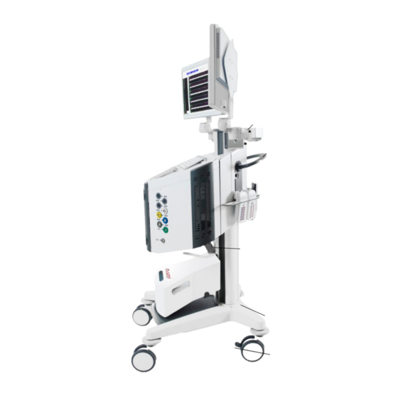
- Page 22 System On/Off Switch Analog and Digital Inputs Speakers and Outputs Keyboard and Touchpad Drive Headstage, Headbox modules Storage Unit and Remote connections Figure 5: Main Unit and Trolley Front View Neuro Omega User Manual Page 22 for Medical Applications V1.4.2...
- Page 23 Handle Headbox Modules and Remote Storage Main unit power and switch, Ethernet connections, Audio output and USB Remote Power cable Isolation Transformer Figure 6: Main Unit and Trolley Side View Neuro Omega User Manual Page 23 for Medical Applications V1.4.2...
-
Page 24: Drive Headstage Module
The Drive Headstage module is mounted on either a Stereotactic frame or frameless systems, and provides the framework for recording and stimulating from up to five electrodes. The Neuro Omega records the data from each of up to five micro contacts and five macro contacts as separate channels. -
Page 25: Drive Headstage
The drive motor, which uses its own scale to measure depth An external scale, calibrated from 0-40 mm with 1 mm resolution, which does the following: Helps you monitor Headstage movement accuracy Neuro Omega User Manual Page 25 for Medical Applications V1.4.2... -
Page 26: Electrode Holder And Bengun
Layout 1 is referred to as X, and layout 2 is referred as + (Figure 12). The electrode holder comes in both these layouts separately. When you Neuro Omega User Manual Page 26... -
Page 27: Frame Adaptor
NexFrame by Medtronic and Starfix by FHC, using adaptors provided by Alpha Omega. Other configurations can be easily customized upon request. 2.2.4. Electrodes Neuro Omega uses electrodes with two possible micro to macro tip distances, as seen in Table 4. Table 4: Tip Distances Electrode Model... -
Page 28: Electrode Input Cable
2.2.6. Cannulas Neuro Omega uses a number of cannula models of differing lengths. The electrode within the cannula is inserted based on length, thereby affecting its starting depth and distance from target, as seen in Table 5. Measurements are in millimeters. -
Page 29: Using Crw And Micromar Frames
Figure 13 shows a distance of 25 mm from the tip of the cannula to the target. The arc of the CRW is 160 mm to the target. Figure 13: Using CRW and MicroMar Frames Neuro Omega User Manual Page 29 for Medical Applications V1.4.2... -
Page 30: Using Leksell And Libenger Frames
Headstage assembly. Note: Make sure to set the instrument stop holder (bracket) to +30mm Figure 14: Using Leksell and Libenger Frames Neuro Omega User Manual Page 30 for Medical Applications V1.4.2... -
Page 31: Using Nexframe Frames
Set the drive Headstage to a starting depth of 5mm (Figure 16, Detail B), distance to target is 15mm (target at 20mm depth). Figure 15: Using Nexframe Frames Figure 16: Z Stage (Detail A) and Distance to Target (Detail B) Neuro Omega User Manual Page 31 for Medical Applications V1.4.2... -
Page 32: Using Starfix Frames
Set the drive Headstage to a starting depth of 5mm (Figure 18, Detail B), distance to target is 15mm (target at 20mm depth). Figure 17: Using Starfix Frames Figure 18: T-Scale (Detail A) and Distance to Target (Detail B) Neuro Omega User Manual Page 32 for Medical Applications V1.4.2... -
Page 33: Mer Only Headstage Module
ODULE The MER Only Headstage module provides the framework for recording and stimulating from up to five electrodes. The Neuro Omega records the data from each of up to five micro contacts and five macro contacts as separate channels. The MER Only Headstage module is comprised of the following components: ... -
Page 34: Headbox Modules
16 channels, with one + (plus) input and one - (minus) input touch-proof connectors for each channel One ground touch-proof connector (black) One global stimulation return touch-proof connector (white) Figure 20: EMG Headbox Module Neuro Omega User Manual Page 34 for Medical Applications V1.4.2... - Page 35 Gray: Module 1 Blue: Module 2 Yellow: Module 3 White: Module 4 Black: Module 5 Red: Module 6 Green: Module 7 Neuro Omega User Manual Page 35 for Medical Applications V1.4.2...
-
Page 36: Remote Control
Save: Starts saving the current data set to the log file Channel: Two buttons to toggle between different channels Drive: Thumb wheel button to advance the electrode up and down (in/out), with speed control Neuro Omega User Manual Page 36 for Medical Applications V1.4.2... -
Page 37: Chapter 3. Preparing The Neuro Omega System
PREPARING THE NEURO CHAPTER 3. OMEGA SYSTEM This workflow describes how to prepare the Neuro Omega system for surgery, and is the prerequisite for microelectrode recording, for identifying the target To prepare the Neuro Omega system: Clean and sterilize the Neuro Omega system, as described in section 3.1. - Page 38 Preparing the Neuro Omega System Clean the Drive Headstage/MER Only Headstage and the Headstage cable (Table 6) by following the hospital cleaning procedure for electronic devices. Assemble the Drive Headstage assembly, as described in section 3.4. Warnings: When cleaning the Electrical Components (Drive Headstage/MER Only Headstage...
- Page 39 Preparing the Neuro Omega System Visually inspect the items to ensure there is no visible soil. Referring to the Sterilization Checklist, Table 9, in the STERRAD NX, sterilize the Headstage, its cable, and its screws, as follows: Remove all screws from the Headstage.
- Page 40 Preparing the Neuro Omega System Headstage Sterrad screws Figure 23: STERRAD Sterilization Tray With the autoclave, sterilize those components marked for sterilization in the Sterilization Checklist, Table 9: Remove all screws from the microelectrode holder and the Bengun. Collect the items described in Table 7, and then do the following: ...
- Page 41 Preparing the Neuro Omega System Reference Sterilization in Figure Item Photo Special Notes Method Do not take apart for sterilization Nexframe / Starfix frame Autoclave adaptor Available as a sterile accessory, as described in section 3.1.2. Tips must always be ...
- Page 42 Preparing the Neuro Omega System Reference Sterilization in Figure Item Photo Special Notes Method DBS Ruler Autoclave Remove lead holder base DBS holder Autoclave Remove lead holder base Nexframe / Starfix DBS Autoclave holder Autoclave Before sterilization, remove all screws.
- Page 43 Preparing the Neuro Omega System Reference Sterilization in Figure Item Photo Special Notes Method M icroelectrode holder and Autoclave Bengun screws Screwdriver Autoclave Figure 24: Autoclave Tray Table 8: Autoclave Parameters Sterilizer Type Prevacuum Preconditioning Pulses M inimum Temperature 132C...
-
Page 44: Sterilization Checklist
3.1.2. Sterile Items In addition to the non-sterile single use items, Alpha Omega offers sterile alternatives. With these accessories, there is no need for additional sterilization. The accessories can be transferred into the sterile field through the sterilization pouch. -
Page 45: Setting The Electrode Starting Point
Preparing the Neuro Omega System Sterile Electrodes Sterile Cannulas and Stylets Sterile Electrode Cable 3.2. ETTING THE LECTRODE TARTING OINT Note: This section does not apply for the MER Only Headstage The electrode starting depth is set based on the calculated distance above the target. The electrode tip must be flush with the end of the cannula, placing the electrode tip at the same distance from the target as the cannula tip. -
Page 46: Setting Electrode Starting Depth Method 1
Preparing the Neuro Omega System 3.2.1. Setting Electrode Starting Depth Method 1 This procedure describes method 1 for setting the starting depth of the electrodes, which is simpler. To set the starting depth of the electrodes: Refer to Table 5: Cannula Models, and based on the cannula you are using, adjust the turn wheel to the correct starting depth. - Page 47 Preparing the Neuro Omega System Tighten the Bengun screw. Figure 26: Holding Screw Attach desired electrode holder (x or +) to the Drive Headstage, an d secure screw Figure 27: Attaching Electrode Holder Neuro Omega User Manual Page 47 for Medical Applications V1.4.2...
- Page 48 Preparing the Neuro Omega System Attach the Drive Headstage to the frame base adaptor and tighten the screw on the back side of the Drive Headstage. Figure 28: Attaching Driving Unit Remove an electrode from the sterilization tray or sterile packet. Pull the electrode tip back into its protective sheath (Figure 29).
- Page 49 Preparing the Neuro Omega System Once the electrode is in the cannula, push the electrode into the electrode holder all the way until it reaches the metal collar, and tighten the microelectrode holder screw. Figure 31: Electrode in Place Push the electrode micro tip to expose it, and then turn the manual wheel until the electrode and its tip are extended outside the cannula.
- Page 50 Preparing the Neuro Omega System Slowly turn the thumb wheel in the opposite direction to retract the electrode into the cannula, until the tip of the electrode is flush with the tip of the cannula. Doing this against a white background will help to make the tip stand out.
-
Page 51: Assembling The Headstage
3.3. SSEMBLING THE EADSTAGE Note: This section does not apply for the MER Only Headstage This procedure describes how to assemble the Neuro Omega Drive Headstage on the frame. Prerequisites: Set the electrode starting point, as described in section 3.2... - Page 52 Preparing the Neuro Omega System Frame attached to the skull of the patient, and the area of entry prepared To assemble the Headstage: Attach the Bengun to the frame adaptor (Figure 37), in the configuration matching that of the electrode holder, either X or +.
- Page 53 Preparing the Neuro Omega System Holding the cannula from the stylet collar, insert the cannula through the Bengun hole (Figure 39) and into patient’s tissue. Figure 39: Inserting the Cannula through the Bengun Hole Tighten the Bengun screw (Figure 40), and then remove the stylet from the cannula.
- Page 54 Preparing the Neuro Omega System Repeat steps 2 and 3 for each electrode you are using. Loosen the screw on the Headstage scale pointer, attach the electrode holder to the drive, and then tighten the screw. Figure 41: Attaching the Electrode Holder to the Drive Connect the Drive Headstage green cable to the Drive Headstage.
- Page 55 Preparing the Neuro Omega System Attach the Drive Headstage to the frame adaptor and secure screw. Figure 43: Inserting Electrode into Electrode Holder Verify that the tip of the electrode is retracted, and then insert the electrode through the hole of the electrode holder and then into the cannula, until the collar where it catches on the drive.
- Page 56 Preparing the Neuro Omega System 11. Repeat steps 9 and 10 for each electrode you are using. Figure 46: All used electrodes inside 12. To connect the input cable, do the following: Connect the input cable to the Drive Headstage.
- Page 57 Preparing the Neuro Omega System Connect ground black wire alligator to any bengun screw Figure 48: Connect Electrode Input Cable Connect the red wires to the red micro tip connectors. Figure 49: Connect Electrode Input Cable Neuro Omega User Manual Page 57 for Medical Applications V1.4.2...
- Page 58 Preparing the Neuro Omega System Expose electrode tip. Figure 50: Connect Electrode Input Cable Connect the yellow wire to the yellow macro tip connector. Figure 51: Connect Electrode Input Cable Neuro Omega User Manual Page 58 for Medical Applications V1.4.2...
-
Page 59: Headbox Modules Assembly
In order to use a video monitor as a part of the visual stimulator, it should be connected to the Neuro Omega trolley isolated power source. Operation in close proximity (for example 1 m) to a shortwave or ... -
Page 60: Assembling The Eeg Module
Preparing the Neuro Omega System This procedure describes how to assemble the EMG module, for use in implanting the DBS or advanced research. To assemble the EMG module: Connect the EMG module to the like-colored port on the Main Unit, using the like-colored cable. -
Page 61: Connecting External Systems
System 3.5. ONNECTING XTERNAL YSTEMS This procedure describes how to connect any external systems to the Alpha Omega, such Matlab or C++ system External analog or digital input or output systems You can power the systems through the trolley’s isolation transformer, or through an independent isolation transformer. - Page 62 Preparing the Neuro Omega System On the Input/Output panel, connect the system to the required connection. Repeat the above steps for each system you want to connect. Neuro Omega User Manual Page 62 for Medical Applications V1.4.2...
-
Page 63: Chapter 4. Operation Of The Neuro Omega System
EURO MEGA YSTEM FOR MPLANTING THE Prepare the Neuro Omega system for use, as described in section CHAPTER Power on the Neuro Omega, as described in section 4.2. Do one of the following: If the patient’s info has not yet been supplied, then supply the patient’s info, as described in section 4.4. -
Page 64: Powering On The Neuro Omega
11. Define, and then during stimulation monitor, the potential evoked by stimulation, as described in section 4.21. 12. Implant the DBS Electrode, as described in section 4.21Error! Reference source not found.. 13. Starting the Neuro Omega Player, as described in section 4.23. 4.2. OWERING N THE... -
Page 65: Create New Workspace
Press on New button in the Choose Workspace Templates Window (Figure 55). System Modules Window (Figure 56) will appear. This window contains all the system modules ports according to the system configuration. Only available modules will appear. Neuro Omega User Manual Page 65 for Medical Applications V1.4.2... -
Page 66: 4.3.1.1. Eeg Module
Default mapping. By pressing Default, the contacts will be named according to the contact type and Headbox number. User defined map, using free text. Click the channel name, and then change it as required. Neuro Omega User Manual Page 66 for Medical Applications V1.4.2... -
Page 67: Emg Module
Contacts that are not mapped will be marked as “Not used”. Note: If you used all the map locations, the other contacts will be marked as “Not used”. Neuro Omega User Manual Page 67 for Medical Applications V1.4.2... -
Page 68: Adio Panel
Digital Output 1-8 Additional Digital Input Additional Digital Output Analog Input 1-8 Analog Output 1-8 Port 1 - 16 bit Port 2 -16 bit Neuro Omega User Manual Page 68 for Medical Applications V1.4.2... - Page 69 Write the workspace name in the New Workspace Template File Name. Press Save. Choose Workspace Window will appear with all the current workspaces. Choose the Workspace you created and press Done. Figure 60: Save Workspace Template Neuro Omega User Manual Page 69 for Medical Applications V1.4.2...
-
Page 70: Edit Workspace
This section describes which windows will appear according to the Workspace configuration. Module Windows Drive Continuous group per all the drive SPK channels. Continuous group per all the drive Macro LFP channels. Segmented group per all the drive segmented channels. Neuro Omega User Manual Page 70 for Medical Applications V1.4.2... -
Page 71: Supplying Patient Info
This procedure describes how to supply patient info for the patient on whom the operation is to be performed. It is a prerequisite for recording neural activity for a new patient. To supply patient info for a new patient: Neuro Omega User Manual Page 71 for Medical Applications V1.4.2... -
Page 72: Selecting An Existing Patient
This procedure describes how to select a patient on whom the operation is to be performed, whose info was supplied on an earlier occasion. This is a prerequisite for recording neural activity for an existing patient. To select an existing patient: Neuro Omega User Manual Page 72 for Medical Applications V1.4.2... -
Page 73: Neuro Omega Interface Navigation
The main window appears. 4.6. EURO MEGA NTERFACE AVIGATION The Neuro Omega interface is made up of the following components: Toolbar: See section 4.6.1 for more information. Workspace: See section 4.6.2 for more information. Trajectory Graph: See section 4.6.2.1 for more information. - Page 74 Stim Channel: Allows you to change the channel receiving stimulation (see section 4.20.2) Stim Amplitude: Allows you to change the amplitude of the stimulation (see section 4.20.2) Stim: Applies stimulation (see section 4.20.2) Neuro Omega User Manual Page 74 for Medical Applications V1.4.2...
-
Page 75: Workspace
Figure 64: Workspace The following procedures describe actions you can perform on Workspace windows in the course of using the Alpha Omega system for implanting the DBS electrode and advanced research: To close and open a Workspace window, see section 4.6.2.1. -
Page 76: Closing And Opening A Workspace Window
From the toolbar, click Window List. The Window dialog box opens (see Figure 65). Select the checkboxes of the windows you want to open. The windows appear in the Workspace. Neuro Omega User Manual Page 76 for Medical Applications V1.4.2... -
Page 77: Popping A Workspace Window In And Out
Omega window, which is helpful when dealing with a large number of Workspace windows. To pop a Workspace window in and out of the main Alpha Omega window: In the Workspace, in the upper-left hand corner of the Workspace window, click , and then click Pop Out. -
Page 78: Trajectory Graph
See Figure 66 for a description of the Trajectory graph. Left/Right Trajectory OPRA Distance to Target Scale Macro Tip M icro Tip Contact Trajectory Bengun Image 1 Second Signal Trace Color Bar Figure 66: Trajectory Graph Neuro Omega User Manual Page 78 for Medical Applications V1.4.2... -
Page 79: Viewing System Diagnostics
This procedure describes how to view system diagnostics, in the System State dialog box. Note: Viewing system diagnostics should be done in conjunction with an Alpha Omega trained user. This should be used as a troubleshooting step. To view System Diagnostic: Press CTRL+SHIFT+A. -
Page 80: Event Definition
To define events: From the toolbar, click Events Properties. The Events Control Panel appears (Figure 68), which contains a number of predefined events for convenience. Figure 68: Events Control Panel Neuro Omega User Manual Page 80 for Medical Applications V1.4.2... - Page 81 See for a description of the Events Definition table. Figure 69: Events Definition Dialog Click Add. The Create Event dialog box opens to allow you to add an event (Figure 70). Figure 70: Create Event Dialog Box Neuro Omega User Manual Page 81 for Medical Applications V1.4.2...
-
Page 82: Editing Events
See for a description of the Events Definition table. Select the event you want to edit, and then click Edit. The Create Event dialog box opens to allow you to edit the event (see Figure 70). Neuro Omega User Manual Page 82 for Medical Applications V1.4.2... -
Page 83: Deleting An Event
First column (no title): A checkbox appears here after an event is defined. When this box is checked, the event on that line appears in the Events Control Panel dialog as a button; otherwise, it will appear in the drop down list. Neuro Omega User Manual Page 83 for Medical Applications V1.4.2... -
Page 84: Verifying Diagnostic Indicators
ERIFYING IAGNOSTIC NDICATORS This procedure describes how to verify that all Neuro Omega system components are connected, and that the Main Unit is reading them correctly. To verify diagnostic indicators: On the toolbar, check if any diagnostic indicators appear, as follows: ... - Page 85 Clear Save in Each Site if you want to manually click Save to start saving Headstage and Headbox data manually, and then proceed to step 7. Note: For more information about saving, see section 4.19. Neuro Omega User Manual Page 85 for Medical Applications V1.4.2...
-
Page 86: Verifying Starting Depth
From the Logging Duration dropdown list, select the length of time for Neuro Omega to save data to the log file. The Infinite checkbox can be selected if nonstop saving is required. Select the Save while Moving checkbox if you want Neuro Omega to continue saving data to the log file after it has started, or after you have clicked Save –... -
Page 87: Creating A New Trajectory
Figure 72: Set Position Dialog Box Manually set the drive position, as described in section 4.12. A popup appears asking if you want to move the drive to the starting depth. Neuro Omega User Manual Page 87 for Medical Applications V1.4.2... - Page 88 If the drive must advance to reach the starting position, then you must advance it manually. The New Trajectory dialog box appears (Figure 73). Figure 73: New Trajectory Dialog Box Neuro Omega User Manual Page 88 for Medical Applications V1.4.2...
-
Page 89: Setting Drive Position
In the upper field, enter the value you read on the drive. Click OK. Neuro Omega compares the value you entered with the 2nd feedback, which is the value from the motor. One of the following happens: Neuro Omega User Manual Page 89 for Medical Applications V1.4.2... -
Page 90: Checking Impedance
Figure 74: Set Position – Continuing without 2nd Feedback Click OK. The Set Position dialog box closes, and Neuro Omega continues with the value from the drive; not the value from the motor or from the software. Note: If, as in step , you must continue without the feedback from the motor, contact Alpha Omega support. -
Page 91: Manipulating The Drive Headstage
Right-click and drag to move the scale up and down. Left-click and drag to zoom in and out within the scale. To make identifying areas easier, use the Colors bar, as follows: Neuro Omega User Manual Page 91 for Medical Applications V1.4.2... -
Page 92: Monitoring Activity
To monitor a channel: From the Windows List button , select a channel Workspace window. The window appears (Figure 75), with each channel in the window appearing in its own graph. Neuro Omega User Manual Page 92 for Medical Applications V1.4.2... - Page 93 Apply a recording reference to the contact, as described in section 4.15.1.6. Make use of the level line by clicking the line and dragging it up or down. Neuro Omega User Manual Page 93 for Medical Applications V1.4.2...
-
Page 94: Adjusting Channel Scales
The Set Group Scales dialog box appears. In the Time Scale area, enter the duration that the graphs should cover, in milliseconds, and then click OK. The scales change accordingly. Neuro Omega User Manual Page 94 for Medical Applications V1.4.2... -
Page 95: Toggling A Channel's Sound
The channel is grounded. Data still comes in, but it is with low noise because the channel is grounded at the first amplifier. Note: To disconnect the ground and return data streaming in the graph, right click again, and then clear Ground. Neuro Omega User Manual Page 95 for Medical Applications V1.4.2... -
Page 96: Changing A Channel Name
Do not use a contact as a reference that is already referencing another contact. Make sure to use reference contacts that are in close vicinity of the referenced contact. Neuro Omega User Manual Page 96 for Medical Applications V1.4.2... -
Page 97: Monitoring Digital Input Channels
Figure 78: Single-Bit Digital Input Display For each input bit: A colored tic mark indicates the change to active high (1). A white tic mark indicates the change to active low (0). Neuro Omega User Manual Page 97 for Medical Applications V1.4.2... -
Page 98: Monitoring Micro Segmentation Spike Sorting
Online sorting graph, in which the templates are defined from the spikes passing the threshold Template histogram, containing a histogram of a template when selected Template graphs, one for each template and one for all spikes passing the threshold Neuro Omega User Manual Page 98 for Medical Applications V1.4.2... - Page 99 (Template 3): When selected, only spikes matching template 3, its template points, its window discriminator if active, and its histogram are displayed, in addition to all unsorted spike segments. Neuro Omega User Manual Page 99 for Medical Applications V1.4.2...
-
Page 100: Defining Spike Sorting Templates
If you want to sort the spikes crossing the level line in the falling direction, select the down arrow Note: If the down arrow does not automatically appear, select the up arrow first – and it appears. Neuro Omega User Manual Page 100 for Medical Applications V1.4.2... - Page 101 Move the corresponding window cursor to the segments comprising the template in the following ways: Drag the window cursor. Enlarge the window cursor by dragging one or both of its horizontal ends. Neuro Omega User Manual Page 101 for Medical Applications V1.4.2...
-
Page 102: Defining The Template Variation
The threshold of a template is the similarity a spike must be to the template, in which a low threshold catches more spikes, and a high th reshold, less. The template threshold is defined using the template histogram (Figure 83), which displays a distribution of spike variability. Neuro Omega User Manual Page 102 for Medical Applications V1.4.2... - Page 103 From the toolbar of the online sorting graph, select a template (see Figure 80, page 99). Only that template spikes appear in the graph ; below it, the graph the template histogram appears (see Figure 83). Neuro Omega User Manual Page 103 for Medical Applications V1.4.2...
-
Page 104: Adding Include Windows
Enlarge the Include Window by dragging one or both of its horizontal ends. Note: Verify that the position of the window cursor includes the desired spikes. The actual position of the window cursor along the XY axis does not matter. Neuro Omega User Manual Page 104 for Medical Applications V1.4.2... -
Page 105: Monitoring The Spike Templates
Set Group Amplitude. The Set Group Scale dialog box appears (Figure 84). Figure 84: Set Group Scale Dialog Box Adjust the Voltage Scale, and then click OK. The voltage scale is adjusted. Neuro Omega User Manual Page 105 for Medical Applications V1.4.2... -
Page 106: Monitoring Spikes In The Spikes Raster Graph
Set the threshold level for the spikes composing the raster by dragging the level line up or down the voltage scale. From the Windows List button , select the spikes raster window. The spikes raster window appears (Figure 85). Neuro Omega User Manual Page 106 for Medical Applications V1.4.2... - Page 107 Note: You can change the duration also in the graph itself, by dragging the time scale at the bottom. Neuro Omega User Manual Page 107 for Medical Applications V1.4.2...
-
Page 108: Monitoring Spikes In The Interspike Interval (Isi) Graph
Continue with step 5. If you want the ISI graph composed of spikes determined by the level line in the micro segmentation window, then continue with step 2. Neuro Omega User Manual Page 108 for Medical Applications V1.4.2... -
Page 109: Monitoring Eeg Signals In Color Density Spectral Array Graph
Color is determined by the amplitude – blue color for the smallest values and red color for the Neuro Omega User Manual Page 109 for Medical Applications V1.4.2... - Page 110 The level line is white, while the templates match the colors of the template match windows. Right-click in the graph area, and then select Options. The Color Density Spectral Array dialog box appears (Figure 89). Neuro Omega User Manual Page 110 for Medical Applications V1.4.2...
- Page 111 After field. From the Spectral Edge section, set an edge to display the percentage of power under the displayed frequency. Neuro Omega User Manual Page 111 for Medical Applications V1.4.2...
-
Page 112: Opra
Real-Time Refinement of Subthalamic Nucleus Targeting Using This process is described at length in Bayesian Decision-Making on the Root Mean Square Measure , by Moran, Bar-Gad, Bergman, and Israel. Neuro Omega User Manual Page 112 for Medical Applications V1.4.2... -
Page 113: Opra Best Practices
Move the threshold for spike sorting outside the noise, so that the firing rate is not calculated from the noise, as OPRA takes the firing rate into account. Ensure that Save in Each Site is selected, as described in section 4.9. Neuro Omega User Manual Page 113 for Medical Applications V1.4.2... -
Page 114: User Events
To mark an event, in the Predefined Events area, do one of the following: Select an event button. From the dropdown list, select an event. Click Send. The event is marked in the log file. Neuro Omega User Manual Page 114 for Medical Applications V1.4.2... -
Page 115: Marking Events From The Events Definition Table
The following happens (Figure 91): The text field is enabled. The Mark button changes to Cancel. After entering text in the Remarks field, the Send button activates. Neuro Omega User Manual Page 115 for Medical Applications V1.4.2... -
Page 116: Trajectory Printing
Trajectory graph, as follows: Each row of the graph describes the activity of one recording site. The recording sites are divided into pages of ten to a page. Neuro Omega User Manual Page 116 for Medical Applications V1.4.2... -
Page 117: Printing An Active Track
Trajectory graph, as follows: Each row of the graph describes the activity of one recording site. The recording sites are divided into pages of ten to a page. Neuro Omega User Manual Page 117 for Medical Applications V1.4.2... - Page 118 From the Amplitude dropdown list, select the amplitude of the traces that you want to appear in the print job, in millivolts. Click Print. The trajectory is printed. Neuro Omega User Manual Page 118 for Medical Applications V1.4.2...
-
Page 119: Saving Data To The Log File
Note: You can save manually even when you have configured automatic saving. 4.20. TIMULATION Perform stimulation after successfully determining placement (see section 4.1, step 9). The workflow for stimulation is as follows: Neuro Omega User Manual Page 119 for Medical Applications V1.4.2... -
Page 120: Setting Up Stimulation
In the Stimulation Setup dialog box, do the following: Verify that Stimulation is Enabled. For a beep to sound for the duration of the stimulation, select Sound during Stimulation. Neuro Omega User Manual Page 120 for Medical Applications V1.4.2... - Page 121 In the Square Wave area, from the Pulse Shape dropdown list, select one of the waveforms: Biphasic - Asymmetric Biphasic – Initial Negative Biphasic – Initial Positive Monophasic – Initial Negative Monophasic – Initial Positive Note: Neuro Omega User Manual Page 121 for Medical Applications V1.4.2...
-
Page 122: Applying Stimulation To The Patient From The Toolbar
Macro button to select either micro or macro, and then press the arrow buttons to select the channel. To adjust the current amplitude of the stimulation if necessary (in milliamps): Neuro Omega User Manual Page 122 for Medical Applications V1.4.2... -
Page 123: Monitoring Stimulation In The Current Monitor Window
When the bar is green, stimulation is working correctly. When the bar is purple, the measured stimulation value is below the requested value by 30% or more. Neuro Omega User Manual Page 123 for Medical Applications V1.4.2... -
Page 124: Defining And Monitoring The Evoked Potential
To define and monitor the evoked potential: From the Windows List button , select the Evoke Potential window. The Evoke Potential window appears (Figure 96). Neuro Omega User Manual Page 124 for Medical Applications V1.4.2... - Page 125 Omega System Figure 96: Evoke Potential Window Right-click in the graph area, and then select Options. The Options dialog box appears (Figure 97). Figure 97: Evoked Potentials Options Dialog Box Neuro Omega User Manual Page 125 for Medical Applications V1.4.2...
- Page 126 From the Digital Input Trigger dropdown list, select a trigger for the tool to start creating the time-locked averages: Select a digital input trigger. The Digital Input Trigger Direction area becomes active (Figure 98). Neuro Omega User Manual Page 126 for Medical Applications V1.4.2...
- Page 127 To reduce the total amount of time displayed in the graph, drag the time scale to the right. To expand the voltage scale, drag up on the scale. To contract the voltage scale, drag down on the scale. Neuro Omega User Manual Page 127 for Medical Applications V1.4.2...
-
Page 128: Defining And Monitoring The Peristimulus Histogram (Psth)
The yellow line is synchronized with the given trigger. Upper part: draws a histogram of the averages of the sorted spikes. Neuro Omega User Manual Page 128 for Medical Applications V1.4.2... - Page 129 The PSTH window appears (Figure 96, page 125). Figure 100: PSTH Window Right-click in the graph area, and then select Options. The Options dialog box appears (Figure 97, page 125). Figure 101: Evoked Potentials Options Dialog Box Neuro Omega User Manual Page 129 for Medical Applications V1.4.2...
- Page 130 To clear the screen for a fresh start, right-click in the graph area, and then select Clear. During stimulation, from the Windows List button , select the PSTH window. The PSTH window appears (Figure 99), displaying signals based on the triggering in real time. Neuro Omega User Manual Page 130 for Medical Applications V1.4.2...
-
Page 131: Operation Of The Neuro Omega Player Mode
4.23.1. Player Offline Mode Powering the Player On. This procedure describes how to power on the Neuro Omega Player in offline mode. Power on the computer and double click the Main Player shortcut. The Patient window appears (Figure 103). Neuro Omega User Manual Page 131 for Medical Applications V1.4.2... - Page 132 From the Operations area, click the chosen file name. The patient data is updated. Click Start Player. Neuro Omega Player Interface The Neuro Omega Player interface is made of the following components: Toolbar: See section 4.6.1 for more information.
- Page 133 : plays or resumes to play the selected file . Pause button : Pause the played file. Previous/next button : enables the user to Select/Open/Play the previous/next playlist entry. Neuro Omega User Manual Page 133 for Medical Applications V1.4.2...
- Page 134 Operation of the Neuro Omega System Indicates the playing progress Figure 104: Playlist Figure 105: Slider Bar Neuro Omega User Manual Page 134 for Medical Applications V1.4.2...
- Page 135 If the running file includes impedance check, the Imp button turns red, and by pressing the button, a window with the result appears. Stim Setup button opens a window that includes the same data saved, related to the stimulation setup. Neuro Omega User Manual Page 135 for Medical Applications V1.4.2...
-
Page 136: Dry Run: Dbs Electrode Handling
(Figure 106). Figure 106: Disconnecting the Electrodes Loosen the retaining screws on the electrode holder, and then remove all of the electrodes (Figure 107). Figure 107: Removing the Electrodes Neuro Omega User Manual Page 136 for Medical Applications V1.4.2... - Page 137 Attach and secure the DBS holder socket to the Drive Headstage. It attaches and locks in the same place and the same way as did the electrode holder (Figure 109). Figure 109: Attaching the DBS Holder Socket Neuro Omega User Manual Page 137 for Medical Applications V1.4.2...
- Page 138 DBS from being pinched by the clamps (Figure 111). Figure 111: Threading the DBS into the DBS Holder The 237 marker is where the micro-tip was (Figure 112) Figure 112: the 237 Marker Neuro Omega User Manual Page 138 for Medical Applications V1.4.2...
- Page 139 Figure 113: Locking the Clamps onto the DBS Remove the DBS holder from the ruler (Figure 114). Figure 114: Removing the DBS Holder from the Ruler The DBS electrode is now measured to the correct length. Neuro Omega User Manual Page 139 for Medical Applications V1.4.2...
- Page 140 Operation of the Neuro Omega System 10. Bring the DBS holder to the Drive Headstage Assembly (Figure 115). Figure 115: Threading the DBS into the Cannula Neuro Omega User Manual Page 140 for Medical Applications V1.4.2...
-
Page 141: Chapter 5. Advanced Capabilities
For Macro, see section 5.2.2. For EEG, see section 5.2.3. For EMG, see section 5.2.4. You can also change a channel name, as described in section 5.2.5. Neuro Omega User Manual Page 141 for Medical Applications V1.4.2... -
Page 142: Controlling Micro Filtering And Sampling Properties
Figure 116: Channel Settings Dialog Box (Micro) Select the channels whose properties you want to edit, and then click Filter Properties. The Filter Properties (Micro) dialog box appears (Figure 117) Neuro Omega User Manual Page 142 for Medical Applications V1.4.2... - Page 143 From the HP (Hz) slider bar, select the high pass filter for the LFP signals. If the checkbox is not selected, it will be only HW filters. iv. From the LP (Hz) slider bar, select the low pass filter for the LFP signals. Neuro Omega User Manual Page 143 for Medical Applications V1.4.2...
-
Page 144: Controlling Macro Filtering And Sampling Properties
Press CTRL+SHIFT+M to open the system menu.. Select Options > Macro Settings. The Channels Settings (Macro) dialog box appears (Figure 118), displaying relevant information on all of the channels derived from the macro contact type. Neuro Omega User Manual Page 144 for Medical Applications V1.4.2... - Page 145 In the Macro Contacts field, enter the contacts you want to edit, either a single contact number or a range of contacts separated by a comma. For example selecting electrodes 1, 3, 4, 5, and 7 is done by specifying 1, 3-5, Neuro Omega User Manual Page 145 for Medical Applications V1.4.2...
-
Page 146: Controlling Eeg Filtering And Sampling Properties
Press CTRL+SHIFT+M to open the system menu. Select Options EEG Settings. The Channels Settings (EEG) dialog box appears (Figure 120), displaying relevant information on all of the channels derived from the micro contact type. Neuro Omega User Manual Page 146 for Medical Applications V1.4.2... - Page 147 7. It is also possible to pre-select electrodes from the Channels Properties window. In the Reference Contact dropdown list, select the contact to be used as the reference in recording. See section 4.15.1.6 for more information on flexible referencing. Neuro Omega User Manual Page 147 for Medical Applications V1.4.2...
-
Page 148: Controlling Emg Filtering And Sampling Properties
Press CTRL+SHIFT+M to open the system menu. Select Options EMG Settings. The Channels Settings (EMG) dialog box appears (Figure 122), displaying relevant information on all of the channels derived from the micro contact type. Neuro Omega User Manual Page 148 for Medical Applications V1.4.2... - Page 149 7. It is also possible to pre-select electrodes from the Channels Properties window. In the Reference Contact dropdown list, select the contact to be used as the reference in recording. See section 4.15.1.6 for more information on flexible referencing. Neuro Omega User Manual Page 149 for Medical Applications V1.4.2...
-
Page 150: Changing Channel Names
Select Options, and then the contact containing the channel whose name you want to change. The settings dialog box of the contact appears (see Figure 116, page 142 for example). Click Change Name. The Channels Properties dialog box appears (Figure 124). Neuro Omega User Manual Page 150 for Medical Applications V1.4.2... -
Page 151: Logging Options
Logging options are used to define what is saved to data files and how it is saved. Neuro Omega saves files in the *.mpx format, which is Alpha Omega’s proprietary binary format. For each recording session, which starts when the Neuro Omega software opens, an *.lsx file is also saved, which is a text files that lists all the files saved in the recording... - Page 152 Figure 125: Logging Options Dialog Box In the Save Channels area, select the channels you want to save, by doing the following: Click Select Channels. The Saving Channels dialog box appears (Figure 126). Neuro Omega User Manual Page 152 for Medical Applications V1.4.2...
- Page 153 5.2.1 In the General Purpose Inputs area, select the input channels that you want to save, as follows: ANALOG-IN ADD ANALOG-IN PORT UD InPort Neuro Omega User Manual Page 153 for Medical Applications V1.4.2...
- Page 154 1 on the selected digital input channel, and stops saving after receiving the value 0. If selected, the Triggers area activates (Figure 127). Figure 127: Triggers Area Activated The logging by trigger behavior is illustrated in Figure 128. Neuro Omega User Manual Page 154 for Medical Applications V1.4.2...
- Page 155 The naming convention is as follows: <brain hemisphere><trajectory number><trajectory depth><incremental index starting with 001> For example: RT1D1.500F0001 Note: The default file location is under the patient reference in the surgeries data folder on C:\Surgeries_data. Neuro Omega User Manual Page 155 for Medical Applications V1.4.2...
-
Page 156: Saving Files By Digital Triggers
NALOG UTPUTS The Neuro Omega system comes standard with eight analog output BNC connectors on the ADIO panel (see Figure 3, page 20). It is possible to route any of the Drive Headstage or Headbox signals to any of the analog outputs. Any electrode signal sent to the analog output is amplified to a total of 4000 times, which includes th e Drive Headstage gain. -
Page 157: Routing A Pre-Selected Channel
Click Apply to apply the new settings. Click OK to apply the new settings and close the dialog box. Upon receiving a signal, the selected channel outputs to the external component. Neuro Omega User Manual Page 157 for Medical Applications V1.4.2... -
Page 158: Routing The Channel In Focus
ETTINGS This procedure describes how to define impedance settings, which are used to define the sine wave used to test the impedance of the recording electrodes. To define impedance settings: Neuro Omega User Manual Page 158 for Medical Applications V1.4.2... - Page 159 In the Input Cable Length, define the length of the wire used before the first amplifier. Do one of the following: Click Apply to apply the new settings. Click OK to apply the new settings and close the dialog box. Neuro Omega User Manual Page 159 for Medical Applications V1.4.2...
-
Page 160: Chapter 6. Technical Specifications
Technical Specifications TECHNICAL SPECIFICATIONS CHAPTER 6. Specifications for the Neuro Omega system appear in the following sections: General Sorting Drive Headstage Headbox Modules for EEG/EMG General Purpose Analog Inputs General Purpose Analog Outputs Audio Outputs ... -
Page 161: Sorting
M icro Channel Contact: Raw: 44kHz (sample per Sec) Spike: 44kHz LFP: 1.375kHz (fixed) M acro Channel Contact: LFP: 1.375kHz (fixed) Noise <20μV peak-to-peak @ 10kOhm load Neuro Omega User Manual Page 161 for Medical Applications V1.4.2... - Page 162 M acro Channel Contact: High Pass Range: 0.07 Hz Low Pass Range: 10,000Hz Stimulation Sources 2 Options: 1 source for basic stimulation 10 sources, 1 per channel for advanced stimulation Neuro Omega User Manual Page 162 for Medical Applications V1.4.2...
- Page 163 15mSec. M acro Stimulation: Stimulation artifact on other M icro Recoding channels is up to 15mSec. Stimulation artifact on other M acro Recoding channels is up to 50mSec. Neuro Omega User Manual Page 163 for Medical Applications V1.4.2...
- Page 164 15 to 80 % RH non-condensing Recommended operating 59F to 95F or 15C to 35C conditions: Humidity 20 to 80%RH non-condensing Storage temperature -40F to 140F, -40C to 60C Input power ±5VDC, ±12VDC Neuro Omega User Manual Page 164 for Medical Applications V1.4.2...
-
Page 165: Headbox Modules For Eeg/Emg
HPF: 0.07,2-45 Hz LPF: 200-400 Hz Noise <20μV peak-to-peak @ 1kOhm Stimulation Sources 2 Options: 1 source for basic stimulation 16 sources, 1 per channel for advanced stimulation Neuro Omega User Manual Page 165 for Medical Applications V1.4.2... -
Page 166: Headbox Modules Stimulation For Emg
+-10%. EM G Stimulation: Stimulation artifact on other EM G Recoding channels is up to 25mSec. Neuro Omega User Manual Page 166 for Medical Applications V1.4.2... -
Page 167: General Purpose Analog Inputs
URPOSE NALOG NPUTS Parameter Value Number of Inputs 16 Channels Input Connector 8 BNC and 8 D-type M ale connector Input Range ±5V Gain 0.25 Hardware High Pass Filter None Neuro Omega User Manual Page 167 for Medical Applications V1.4.2... -
Page 168: General Purpose Analog Outputs
Output the signal of any of the high frequency channels Bandwidth DC-3.5kHz (Drive Headstage bandwidth is 0.075-10kHz) Gain Total gain 2000 D/A Converter Output Range ±2.5 Volts D/A Resolution 16 bits Sampling Rate 44kHz Neuro Omega User Manual Page 168 for Medical Applications V1.4.2... -
Page 169: General Purpose Single Bit Digital Inputs
M aximum input frequency 1kHz 6.11. ENERAL URPOSE IGITAL UTPUTS Parameter Value Number of Outputs 16 Channels Output Connector 8 BNC, 8 D-type Female Port Sampling Rate 44kHz Control Script only Neuro Omega User Manual Page 169 for Medical Applications V1.4.2... -
Page 170: Analog Digital Inputs And Outputs Pinout
UTPUTS INOUT The Neuro Omega has an optional Analog/Digital Input/Output package. All inputs and outputs are available on the Input/Output panel of the unit (see Figure 3, page 20). Pinout details for the D-Type connectors are described in the following sections: ... -
Page 171: Add Dig-Out Pinout
Pin Number Pin Number A.In 9 A.In 16 A.In 10 A.In 15 A.In 11 A.In 14 A.In 12 A.In 13 Neuro Omega User Manual Page 171 for Medical Applications V1.4.2... -
Page 172: Add Dig-In Pinout
Pin Number Pin Number D.In 1 D.In 2 D.In 3 D.In 4 D.In 5 D.In 6 D.In 7 D.In 8 D.In 9 D.In 10 D.In 11 D.In 12 Neuro Omega User Manual Page 172 for Medical Applications V1.4.2... - Page 173 Technical Specifications Pin Number Pin Number D.In 13 D.In 14 D.In 15 D.In 16 Strobe Ready Neuro Omega User Manual Page 173 for Medical Applications V1.4.2...
Need help?
Do you have a question about the Neuro Omega and is the answer not in the manual?
Questions and answers