Tektronix THDP0100 User Manual
High voltage differential probes
Hide thumbs
Also See for THDP0100:
- Instruction manual (73 pages) ,
- Installation and safety instructions (30 pages)

Subscribe to Our Youtube Channel
Related Manuals for Tektronix THDP0100


Summary of Contents for Tektronix THDP0100
- Page 1 High Voltage Differential Probes THDP0100/0200 and TMDP0200 User Manual Register now! Click the following link to protect your product. tek.com/register *P077054003* 077-0540-03 May 2023...
- Page 2 Copyright © Tektronix. All rights reserved. Licensed software products are owned by Tektronix or its subsidiaries or suppliers, and are protected by national copyright laws and international treaty provisions. Tektronix products are covered by U.S. and foreign patents, issued and pending. Information in this publication supersedes that in all previously published material. Specifications and price change privileges reserved.
-
Page 3: Table Of Contents
Specifications....................................39 Warranted specifications..............................39 Typical characteristics................................40 Mechanical characteristics..............................41 Nominal characteristics................................41 Performance graphs................................42 Performance verification................................46 Required equipment................................46 TekVPI Calibration Fixture ............................47 Test procedures................................... 47 DC gain Accuracy................................. 48 Rise time..................................49 High Voltage Differential Probes THDP0100/0200 and TMDP0200 User Manual... - Page 4 Contents Test record................................... 50 Adjustments....................................51 Equipment required ................................52 Adjustment procedures................................ 53 Offset zero..................................54 Gain accuracy................................56 DC CMRR..................................57 LF compensation................................58 AC CMRR..................................59 Maintenance....................................61 Host instrument firmware..............................61 Error conditions ...................................61 Cleaning....................................61 Service....................................62...
-
Page 5: Important Safety Information
Do not connect or disconnect probes or test leads while they are connected to a voltage source. Use only insulated voltage probes, test leads, and adapters supplied with the product, or indicated by Tektronix to be suitable for the product. -
Page 6: Probes And Test Leads
Important safety information Do not operate with suspected failures If you suspect that there is damage to this product, have it inspected by qualified service personnel. Disable the product if it is damaged. Do not use the product if it is damaged or operates incorrectly. If in doubt about safety of the product, turn it off and disconnect the power cord. -
Page 7: Service Safety Summary
Dangerous voltages or currents may exist in this product. Disconnect power, remove battery (if applicable), and disconnect test leads before removing protective panels, soldering, or replacing components. Verify safety after repair Always recheck ground continuity and mains dielectric strength after performing a repair. High Voltage Differential Probes THDP0100/0200 and TMDP0200 User Manual... -
Page 8: Terms In This Manual
Important safety information Terms in this manual These terms may appear in this manual: WARNING: Warning statements identify conditions or practices that could result in injury or loss of life. CAUTION: Caution statements identify conditions or practices that could result in damage to this product or other property. Terms on the product These terms may appear on the product: •... -
Page 9: Compliance Information
Overvoltage Category I. For equipment intended to be connected to a mains supply in which means have been taken to substantially and reliably reduce transient overvoltages to a level where they cannot cause a hazard. High Voltage Differential Probes THDP0100/0200 and TMDP0200 User Manual... -
Page 10: Environmental Compliance
This symbol indicates that this product complies with the applicable European Union requirements according to Directives 2012/19/EU and 2006/66/EC on waste electrical and electronic equipment (WEEE) and batteries. For information about recycling options, check the Tektronix Web site (www.tek.com/productrecycling). -
Page 11: Overview
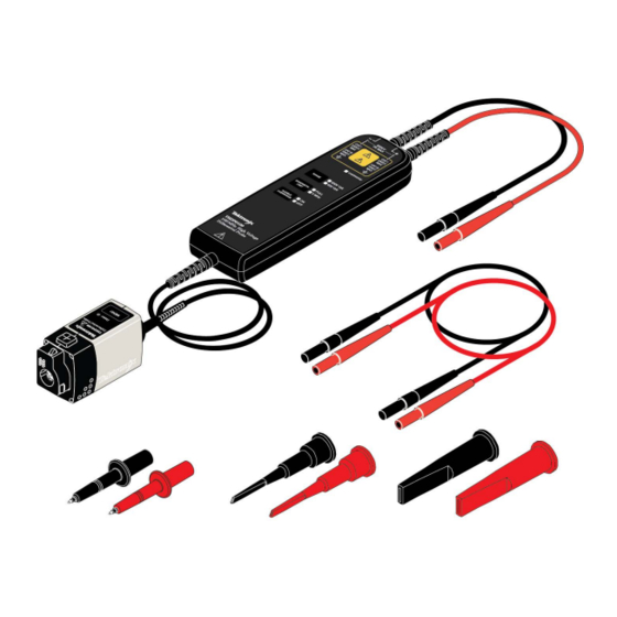
Overview Overview This document provides operating information and specifications for the Tektronix THDP0100/0200 and TMDP0200 high voltage differential probes. The probes share similar functions, properties, and operating procedures, and are discussed first, followed by the specifications, which differ by probe model. Service procedures include performance verification and adjustments. - Page 12 Overview Figure 2: THDP0200 probe with accessories...
- Page 13 Overview Figure 3: TMDP0200 probe with accessories High Voltage Differential Probes THDP0100/0200 and TMDP0200 User Manual...
-
Page 14: Probe Operating Information
If the wear indicator is visible, do not use the probe. Contact Tektronix Service for repair or replacement. WARNING: To avoid electrical shock or fire, keep the probe body and output cable of the probe away from the circuits being measured. -
Page 15: Connecting To The Circuit
Some features differ from those illustrated, such as probe input voltage limit and voltage range, depending on the probe model. The probe release button, Status LED, and MENU buttons are located on the probe control box. High Voltage Differential Probes THDP0100/0200 and TMDP0200 User Manual... - Page 16 Probe operating information Probe release button Press the release button to unlatch the probe from the instrument, and then pull the probe straight out. WARNING: To avoid electrical shock, disconnect the probe inputs from the circuit before disconnecting the probe from the instrument.
- Page 17 The OVERRANGE LED lights if the applied voltage exceeds the selected range. To extinguish the LED, select a higher range. If a higher range is not available, do not attempt to take the measurement with the probe. High Voltage Differential Probes THDP0100/0200 and TMDP0200 User Manual...
- Page 18 Probe operating information Bandwidth limit button and indicators Press the BANDWIDTH LIMIT button to limit the probe bandwidth to 5 MHz. 5 MHz is close to the switching frequency of most switching transistors (FETs) in switch mode power supplies (SMPS). The 5 MHz filter assists in the characterization and testing of power supplies in switch mode by removing all high frequency content, noise and harmonics from the measurement.
-
Page 19: Functional Check
Overrange indicator lights if the input is ~20% over Hot (same Common Mode High or low No signal. If a DC offset voltage is present, zero the DC connection) offset using the AutoZero function. High Voltage Differential Probes THDP0100/0200 and TMDP0200 User Manual... -
Page 20: Autozero
Probe operating information AutoZero The host instrument includes a feature that nulls the DC offset at the output of the probe. To initiate the AutoZero routine, do the following: 1. Allow the probe and oscilloscope to warm up for 20 minutes. 2. -
Page 21: Dc Offset Zero Reset
5. Repeat steps on page 21 through on page 21 for the other range setting on the probe. 6. Perform the DC Offset Zero procedure as described in the previous section. High Voltage Differential Probes THDP0100/0200 and TMDP0200 User Manual... -
Page 22: Accessories And Options
THDP0100 probe standard accessories WARNING: To avoid risk of electric shock or fire, do not use the THDP0100 test probe or hook tip accessories on CAT III or CAT IV circuits. Refer to the ratings tables in the Accessories section of the manual. See... - Page 23 Use the small hook tip (TASH) for probing in hard to reach areas. WARNING: To prevent arc flash, do not use the test probe or hook tips on CAT III circuits. To probe CAT III circuits, use the AC280-FL, AC283-FL, or AC285-FL accessories. High Voltage Differential Probes THDP0100/0200 and TMDP0200 User Manual...
- Page 24 Accessories and options Small Hook Tip (TASH) Use the small hook tip for making connections to small conductors such as component leads. Screw the small hook tip onto the TATP test probe. To use the hook tip, hold the probe body and pull the tip shield back. Hook the tip onto the circuit and release the shield.
- Page 25 Accessories and options Voltage derating for THDP0100 probe standard accessories The THDP0200 and TMDP0200 standard accessories can be used with the THDP0100 probe at the reduced voltage levels listed in this table. Table 1: Combined probe and accessory common-mode voltage and input voltage-to-earth ratings...
-
Page 26: Thdp0200 And Tmdp0200 Probe Standard Accessories
Accessories and options THDP0200 and TMDP0200 probe standard accessories The standard accessories that connect directly to your circuit are shown below, and are described on the following pages. WARNING: To reduce risk of shock or fire, do not exceed either the voltage rating or category ratings of the probe or the probe accessory, whichever is the lesser of the two. - Page 27 Maximum ratings: 1000 V CAT II 1000 V CAT III 10 A One pair of handheld probes are included with the probes. Note: The TP175 must be ordered through Fluke. High Voltage Differential Probes THDP0100/0200 and TMDP0200 User Manual...
- Page 28 WARNING: The probe input rating is derated to 150 V CAT II, 1 mA, when used with the THDP and TMDP series probes. Do not use this pogo pin adapter to measure voltages that exceed this rating. Maximum ratings: 150 V CAT II 1 mA Reorder Tektronix part number: 020-3107-xx (includes 2 Tip Adapters, 2 Cone-Tip Pogo Pins, and 2 Serrated-Tip Pogo Pins)
- Page 29 Plug the probe test leads into the banana plug connectors. Squeeze the grips to expose the hook clip and then clasp it around the circuit test point. Maximum ratings: 1000 V CAT III One pair of hook clips are included with the probes. Reorder Tektronix part number: AC280-FL (one pair) High Voltage Differential Probes THDP0100/0200 and TMDP0200 User Manual...
- Page 30 Maximum ratings: 1000 V CAT III One pair of pincer clips are included with the probes. Reorder Tektronix part number: AC283-FL (one pair) Alligator Clips (AC285-FL) These large insulated alligator clips connect to many circuit components. Maximum ratings:...
- Page 31 For test points <1 inch apart, use the handheld probes with the THV-Browser (shown on the following page). To use the probe holder, do the following: 1. Insert the probe into one of the holder openings so that the Tektronix logo faces the circuit under test. 2. Slide the probe forward to secure it.
- Page 32 The weight of the probe holder keeps the probe in place. CAUTION: If you are probing circuitry with dense contacts such as IC pins, Tektronix recommends that you use insulated probe tip accessories designed to prevent short-circuiting adjacent IC pins or circuitry.
-
Page 33: Thdp And Tmdp Series Probes Optional Accessories
SMA connector on the back of the fixture. The signal can then be measured with another instrument, (for example, a precision DMM), to check and adjust probe qualities such as gain accuracy. Order Tektronix part number: 067-1701-xx High Voltage Differential Probes THDP0100/0200 and TMDP0200 User Manual... -
Page 34: Service Options
This reusable label covers the openings to the service-only adjustments on the back of the probe. To maintain the safety of the probe, the label must be replaced after service adjustments are made to the probe. If the original label becomes damaged or lost, order a replacement label. Order Tektronix part number: 335-2913-xx Service Options Option C3... -
Page 35: Operating Basics
(the common mode voltage specification). The maximum common mode voltage limits vary between probes, from 550 V CAT I for the TMDP0200, to 2300 V CAT I for the THDP0100 probe. You should consider both specifications when choosing a probe for your measurement task. -
Page 36: Measurement Examples
2000 V ). Looking at the maximum measurable differential voltage specifications for the THDP/TMDP series probes, the THDP0100 probe is capable of measuring this signal. See Typical characteristics on page 40. For reference, the rms values of the... -
Page 37: Overrange Detection
. Although this is a lower potential between the inputs than in example 1, it exceeds the differential voltage ratings of the THDP0200 and TMDP0200 probes, so you must use the THDP0100 probe. Figure 7: Measuring two equal-amplitude waveforms that are 120 degrees out of phase Example 3 Your task is to measure two AC waveforms of the same phase, each with an amplitude of 300 V. -
Page 38: Common-Mode Rejection
Operating basics Common-mode rejection The common-mode rejection ratio (CMRR) is the specified ability of a probe to reject signals that are common to both inputs. More precisely, CMRR is the ratio of the differential gain to the common-mode gain. The higher the ratio, the greater the ability of probe to reject common-mode signals. -
Page 39: Specifications
Specifications The specifications shown apply to the THDP/TMDP series probes installed on Tektronix MSO/DSO4000 oscilloscopes. When a probe is used with another oscilloscope, the oscilloscope must have an input impedance of 1 MΩ and a bandwidth equal to or greater than the probe. -
Page 40: Typical Characteristics
Specifications Typical characteristics Typical characteristics describe typical but not guaranteed performance. Table 6: Typical electrical characteristics Characteristics THDP0100 THDP0200 TMDP0200 600 V Range: 600 V DC + 150 V Range: 150 V DC + 75 V Range: 75 V DC + Maximum measurable differential voltage. -
Page 41: Mechanical Characteristics
+ input lead while the – input lead is grounded (by taking a single-ended measurement). High Voltage Differential Probes THDP0100/0200 and TMDP0200 User Manual... -
Page 42: Performance Graphs
Specifications Performance graphs Figure 8: THDP0100/0200 and TMDP0200 impedance plots Figure 9: THDP0100 voltage derating curve... - Page 43 Specifications Figure 10: THDP0200 voltage derating curve Figure 11: TMDP0200 voltage derating curve High Voltage Differential Probes THDP0100/0200 and TMDP0200 User Manual...
- Page 44 Specifications Figure 12: THDP0100 rise time (typical) Figure 13: THDP0200 rise time (typical)
- Page 45 Specifications Figure 14: TMDP0200 rise time (typical) High Voltage Differential Probes THDP0100/0200 and TMDP0200 User Manual...
-
Page 46: Performance Verification
≥50 V, 200 ns pulse width, ≤500 ps rise time, 1 kHz Avtech AVR-E2-B-W-P Probe calibration fixture TekVPI input Tektronix part number 067-1701-xx Digital Multimeter (DMM) 100 mV and 1 V true RMS AC ranges, <±0.3 % accuracy Tektronix DMM4040/4050 Cable Coax, BNC, 50Ω, 36 in... -
Page 47: Tekvpi Calibration Fixture
SMA connector on the back of the fixture. The signal can then be measured with another instrument, such as a precision DMM, to check and adjust the gain accuracy of the probe. Order Tektronix part number 067-1701-xx. -
Page 48: Dc Gain Accuracy
Table 10: DC gain accuracy equipment settings Probe Generator output Probe output voltage Model Range Voltage (rms) Frequency Expected (rms) Measured (rms) THDP0100 600 V 75 V 100 Hz 750 mV ±15 mV 6000 V 75 V 100 Hz 75 mV ±15 mV THDP0200... -
Page 49: Rise Time
50 V 1 kHz ≤2.4 ns 1500 V 50 V 1 kHz ≤2.0 ns TMDP0200 75 V 50 V 1 kHz ≤2.4 ns 750 V 50 V 1 kHz ≤2.0 ns High Voltage Differential Probes THDP0100/0200 and TMDP0200 User Manual... -
Page 50: Test Record
Probe Serial Number: RH%: Temperature: Technician: Date of Calibration: Probe test Range Minimum Incoming Outgoing Maximum THDP0100 gain accuracy 600 V 735 mV 765 mV 6000 V 73.5 mV 76.5 mV THDP0200 gain accuracy 150 V 490 mV 510 mV... -
Page 51: Adjustments
Note: Only probes with serial numbers C020000 and above have internal adjustments. Probes with serial numbers C019999 and below that require adjustments (other than offset zero) must be returned to Tektronix for service. Table 13: THDP and TMDP Series probe adjustments... -
Page 52: Equipment Required
Generator ±100 V variable, 100 Hz square wave, calibrated Fluke 9100 Probe calibration fixture TekVPI inputs Tektronix part number 067-1701-xx Digital Multimeter (DMM) 100 mV and 1 V true RMS AC ranges, <±0.3 % accuracy Tektronix DMM4040/4050 Cable Coax, BNC, 50 Ω, 36 in... -
Page 53: Adjustment Procedures
2. Connect the probe to any channel of the oscilloscope. 3. Verify that the LEDs light on the probe. 4. Turn on the remaining test equipment and let the probe and equipment warm up for 20 minutes. High Voltage Differential Probes THDP0100/0200 and TMDP0200 User Manual... -
Page 54: Offset Zero
Adjustments Offset zero This is the only procedure that applies to all of the probes and all serial numbers. Adjustment notes • For probes with serial numbers C199999 and below, Offset Zero is the only adjustment that can be done to the probe. •... - Page 55 Failure to do so may subject the user to high voltages present in the probe during measurements. If you need a replacement label, refer to the Equipment Required table for the Tektronix part number.
-
Page 56: Gain Accuracy
Table 15: Adjust gain accuracy equipment settings Probe Generator square wave output Probe output voltage Model Range Voltage (rms) Frequency Expected (rms) Measured (rms) THDP0100 600 V 75 V 100 Hz 750 mV ±15 mV 6000 V 75 V 100 Hz 75 mV ±1.5 mV THDP0200... -
Page 57: Dc Cmrr
6. Enable the generator output. Set the oscilloscope vertical to display the signal. For a stable display, connect the generator Sense output to another channel and trigger off of that channel. High Voltage Differential Probes THDP0100/0200 and TMDP0200 User Manual... -
Page 58: Lf Compensation
Set the generator fast-rise (rise time waveform) output frequency to 10 kHz. Set the generator fast-rise output voltage to 50 V Table 17: LF compensation test equipment settings Probe Generator output Model Range Voltage (p-p) Frequency THDP0100 600 V 50 V 10 kHz Table continued…... -
Page 59: Ac Cmrr
2. Connect both of the probe inputs to the red (+) banana connector on the front output of the generator. Use a BNC-banana adapter if necessary. 3. Set the output of the generator to 297 V (105 Vrms) @100 kHz. High Voltage Differential Probes THDP0100/0200 and TMDP0200 User Manual... - Page 60 Adjustments Table 18: AC CMRR test equipment settings Probe Generator output Model Range Voltage (p-p) Frequency THDP0100 600 V 297 V 100 kHz THDP0200 150 V 297 V 100 kHz TMDP0200 75 V 297 V 100 kHz 4. Set the oscilloscope horizontal to 10 μs/div.
-
Page 61: Maintenance
• Connect the probe to a different oscilloscope. If the symptoms remain (they follow the probe), then the probe is defective and must be returned to Tektronix for repair. Signal display If the probe is connected to an active signal source and you do not see the signal displayed on the oscilloscope: •... -
Page 62: Service
Maintenance Service There are no user-serviceable parts in the probes. If your probe requires service, contact your Tektronix service representative or repair center for instructions on returning your probe for repair.
Need help?
Do you have a question about the THDP0100 and is the answer not in the manual?
Questions and answers