Advertisement
Quick Links
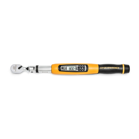
85078, 85079
ELECTRONIC TORQUE WRENCH WITH ANGLE OPERATING INSTRUCTIONS
LCD Display and Button Functions
Audible
Select Unit of
Alert
Measurement
U
• Color LCD
• On/Off
Screen
• Clear
• Exit Current
Setting
1. Power On
1. Verify torque is not being applied to the wrench. Press
Wrench will beep once.
2. The wrench will default to Peak Torque Mode. The last unit of measurement
and last torque setting will display.
3. The wrench is ready to use.
2. Power Off
1. If no torque is applied, wrench will shut off automatically after 90 seconds.
2. To shut off manually, verify torque is not being applied then press
3 seconds.
3. How to Change Unit of Torque Measurement
1. Power on the wrench as described in Section 1.
2. Press
repeatedly to select one of the five torque measurement options:
M
U
NI
· Kg-m
C
S
ET
· Nm
· Ft-lb
· In-lb
· Kg-cm
3. The wrench is ready to use.
4. How to Set Mode
1. There are four mode options:
• P = Peak Torque (default)
• A = Angle
• PA = Peak Angle
1.800.561.8187
• PCt = Target Torque Alert Setting
7. How to Change "Target Torque
Alert" and "Target Angle Alert"
Percentages
1. Power on the wrench as
described in Section 1.
2. Press
M
until the "PCt" mode is reached, then press
U
NI
U
NI
3. The current value will flash on the screen.
C
Value (+) Change Mode
S
ET
4. Press
or
C
M
U
NI
target torque alert can start at a maximum of 50% to the target torque value
C
S
ET
or a minimum of 1% to the target torque value. For example, if your target
torque is 100 ft-lbs and your target torque alert is set at 50%, the alert will
M
start when you reach 50 ft-lbs. Press
NI
M
U
NI
5. The screen will show "dEG" so the target angle alert can be adjusted.
C
S
ET
6. Press
to change the target angle alert setting. Press
C
S
ET
to select when the target angle alert will start. The target angle alert can
start at a maximum of 50 degrees before the target angle or a minimum of 5
degrees before the target angle. Press
Value (-) • Change Torque
7. The wrench is ready to use.
or Angle Value
Setting
8. How to Use Pre-Set Torque Values
• Select Option
Displayed
1. Power on the wrench as
• Select Torque
M
U
NI
described in Section 1.
or Angle Value
2. Press
C
then
S
U
ET
NI
screen will show the setting number
M
U
NI
C
U
NI
at the top of the screen and the torque value will be flashing.
C
for 2 seconds.
S
ET
3. Press
C
or
M
U
NI
4. The wrench is ready to use.
C
S
ET
9. How to Change Pre-Set Torque Values
Pre-Set Torque Values can only be
selected in Peak or Peak Angle modes.
1. Power on the wrench as
M
U
NI
M
U
NI
described in Section 1.
C
for
S
ET
2. Press
then
C
S
U
ET
NI
U
NI
of the screen and the torque value will be flashing.
C
3. Press
or
C
M
U
NI
for 3 seconds, after which the wrench will beep.
C
S
ET
4. Now the pre-set number at the top of the screen will flash. Press
to select the desired torque setting, then press
M
U
NI
saved into the Pre-Set options.
5. Press
again to set the target torque as to the new Pre-set value.
C
S
ET
10. How to Set Torque with Angle
1. Power on the wrench as
described in Section 1.
2. Place the torque wrench on a
M
U
NI
stable flat surface to calibrate.
C
S
ET
3. Press
M
until the "PA" mode is reached, then press
U
NI
4. The screen will show "OOOO" as
C
www.
S
ET
the wrench calibrates, then will
M
U
NI
C
S
ET
M
U
NI
C
. .
S
ET
M
to select when the target torque alert will start. The
S
ET
M
U
NI
C
to save.
S
ET
U
NI
or
C
M
U
NI
C
M
U
S
ET
NI
to save.
C
S
ET
M
U
NI
lb.ft
M
. The
C
S
ET
M
S
U
ET
NI
to select the desired pre-set torque value, then press
C
S
ET
U
M
NI
lb.ft
C
S
ET
. The screen will show the pre-set number at the top
M
M
U
NI
S
ET
to select the desired pre-set torque value, then press
C
S
ET
M
U
NI
U
NI
. The new Pre-Set Value is
C
S
ET
C
M
U
NI
C
S
ET
M
U
NI
C
.
S
ET
information@itm.com
.com
M
U
NI
13. Maximum Capacity Exceeded
1. When the applied torque exceeds
the wrench full-scale capacity the
LCD screen will show red. The
display will show "ovEr".
2. Verify the calibration of the wrench if you know its capacity has been
exceeded.
How to Apply Torque
1. This Electronic Torque Wrench is designed so that when force is properly
applied to the handgrip, a continuous audible signal, the LCD screen display
and vibration in the handle will indicate that the Target Torque or Angle has
M
been attained. DO NOT pull beyond this point.
S
ET
Caution: The audible signal, LCD screen display and vibration in the the handle
are indicators that the proper torque or angle have been attained. Over torqu-
ing beyond these signals could cause fastener failure.
2. To properly apply torque, attach socket securely on torque wrench square
drive and position socket on fastener so that tilting will not occur. Grasp the
center of hand grip and apply a slow steady increasing force perpendicular
(90 degrees) to the torque wrench body and perpendicular (90 degrees) to the
center line of the square drive, socket and fastener.
3. Turn the fastener down with a smooth and even force applied to the handle
M
of the torque wrench. As turning resistance increases, pull more slowly. To
.
assure accuracy, the fastener must be in motion when the torque measure-
S
ET
ment is made.
WARNING: Any change from the above procedure will result in a change of
torque being applied. This includes standard torque wrenches, flex-head
torque wrenches, universal joints, and universal sockets. DO NOT USE universal
joints or universal sockets due to the complexity of determining the associated
error. If you need angular access, use a flex-head torque wrench.
M
Extensions
S
ET
When it is necessary to use an extension that changes the effective lever
M
U
NI
length of the torque wrench, torque being applied will change.
C
or
M
S
ET
Compute adjustments as follows:
TW - Torque set on Wrench
S
ET
TE - Torque applied by the extension to the fastener
TW = (TE x L) / (L + E)
TE = (TW x (L + E)) / L
Notice: Socket extension bars that are axially in line with the square drive do
not cause error and need no adjustment.
M
U
NI
C
S
ET
Advertisement

Related Manuals for Gearwrench 85078


Summary of Contents for Gearwrench 85078
- Page 1 1. When the applied torque exceeds Alert” and “Target Angle Alert” the wrench full-scale capacity the Percentages 85078, 85079 LCD screen will show red. The 1. Power on the wrench as ELECTRONIC TORQUE WRENCH WITH ANGLE OPERATING INSTRUCTIONS display will show “ovEr”.
- Page 2 2. Power on the wrench as described in Section 1. Apply torque and rotate the wrench at a constant moderate speed until alerted show last angle and torque value set. lb.in 3. Press repeatedly to scroll through the different modes. “SEL” will to stop by the continuous audible signal, the LCD Screen display and handle 5.
Need help?
Do you have a question about the 85078 and is the answer not in the manual?
Questions and answers