
Related Manuals for AutoCrib AUTOLOCKER FX


Summary of Contents for AutoCrib AUTOLOCKER FX
- Page 1 Operation Manual Last Revision December 2018 1-800-671-6501 | autocribsupport.com 2882 Dow Avenue Tustin, CA 92780 P a g e...
- Page 2 RMA number on the box(es) that will contain any and all defective parts to be returned. If you do not provide the RMA number or fail to send the defective part back to AutoCrib you be charged for the defective part.
- Page 3 Limitations and Exclusions: This warranty shall not cover or include any of the following and AutoCrib shall have no liability with respect to: Defects or damages which result from accident, misuse, abuse, lack of recommended or...
- Page 4 Regardless of whether the buyer’s limited remedy has failed of its essential purpose, AutoCrib shall not be liable in any event for any special, indirect, incidental or consequential damages, including but not limited to lost profits, nor shall any claim or recovery of any kind exceed the purchase price of the machine or system to which such claim or recovery is made.
-
Page 5: Table Of Contents
Table of Contents Machine General Description & Features .................. 7 Equipment Supplied ........................8 Cautions ............................9 Machine Setup ..........................11 Tools needed for installation ..................... 11 Machine preparation ......................... 11 Installation..........................12 Management Station Configuration ..................18 Computer Setup ........................18 Restore the Database ........................ - Page 6 Exiting the software to access the Microsoft Windows desktop ..........66 Appendix ............................67 Care and Maintenance....................... 67 Technical Specification ......................68 Parts list ............................. 70 Parts list continued ........................71 LED Lights Status: ........................72 P a g e...
-
Page 7: Machine General Description & Features
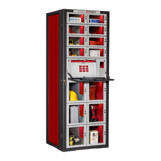
Machine General Description & Features The AutoLocker® FX is the first and only locker system on the market designed to be completely modular in every way. This platform lets you build a custom configured locker system for the unique needs of your company. The rack mounted approach allows you to configure exactly what you need and purchase only what you need. -
Page 8: Equipment Supplied
Equipment Supplied ▪ Frame 24” Deep and 36” or 72” High (Optional Caster Wheels) ▪ Modules (various configurations of doors & drawers which may include AC Power, network, or fan upgrades) ▪ Touch Controller (stand-alone unit) includes; • Dell Optiplex 7040 Micro PC •... -
Page 9: Cautions
Cautions The following cautionary information should be reviewed before the machine is installed. Following these requirements and warnings are required. CAUTION: This machine is designed for indoor usage only. Any other usage will void the Manufacturer’s Warranty. Voltage and Polarity Check It is important that this machine be hooked up to the proper voltage and polarity for your country. - Page 10 Electrical Color Codes: 10 | P a g e...
-
Page 11: Machine Setup
Machine Setup Tools needed for installation ▪ Outlet Tester (May be purchases at electronics store) ▪ Forklift with adjustable forks ▪ Utility dolly ▪ Phillips #2 Screwdriver Machine preparation The FX Locker unit is assembled and packed so that a minimum amount of time is necessary for preparation to install it on location. -
Page 12: Installation
Installation Physical Connections: 1. Move the machine to the desired location 2. Plug the FX AutoLocker into a grounded 110v receptacle 3. Unlock and pull Open the Touch Controller drawer using the key provided with the machine shipment 4. Press and hold the UPS Battery power button for two seconds then release to turn on the power (battery is located towards the back-left corner of the frame behind the touch controller drawer). - Page 13 5. Remove the provided blue 25 foot CAT5 able from the package 6. Using the key provided unlock the left front corner panel and pull straight out then set aside 7. Feed the CAT5 cable through the opening in the chassis (from left to right) located on the top left side of the drawer 13 | P a g e...
- Page 14 8. Connect the right end of the CAT5 cable to the Ethernet Port located behind the PC 9. Run the left end of the CAT5 cable up the side of the chassis and feed through the opening on the top left corner of the machine 14 | P a g e...
- Page 15 10. Pull the cable through and connect to the network 11. Place the left front panel back on: make sure the two studs fit into the round holes and turn the key to lock the panel back in place b. Align the three metal tabs that are located on the frame (bottom, middle, and top) with the three slits located on the front panel cover c.
- Page 16 Additional Frames Connection 1. Using a utilities dolly, position the frames per the site plan 2. Ensure power is OFF at the UPS 3. Pull the ends of the DC Power & Data cables out of both adjoining frames Data – 5 position Hirose DC Power –...
- Page 17 7. Make sure the red termination jumper is located on the last distribution board of the last locker frame in the chain 17 | P a g e...
-
Page 18: Management Station Configuration
Management Station Configuration Computer Setup 1. Connect the monitor using the blue VGA cable 2. Connect the USB keyboard 3. Connect one end of the network cable (CAT5) to the PC, then connect the other end of the network cable to the hub provided or LAN drop 18 | P a g e... - Page 19 5. Press the power button on the computer and monitor 6. Exit out of the AutoCrib software 7. Ask the network administrator to properly configure the network LAN settings on the management station and FX Lockers.
- Page 20 Dell Tower Ports Optical Drive Optical Drive Eject Button Optical Drive bay Media Card Reader (optional) USB 2.0 Connectors (2) Drive activity light Power button, power light Diagnostic lights (4) Headphone Connector Microphone Connector Network Connectivity Light Power Connector Back Panel Connectors Expansion Card Slots (4) Cooling Vents Padlock Ring...
-
Page 21: Restore The Database
Restore the Database AutoCrib Software Must be Turned Off 1. Unzip the file database received from the AutoCrib Professional Services department into C:\Program Files\Microsoft SQL Server\MSSQL13.SQLEXPRESS\MSSQL\Backup on the AutoCab FX PC. 2. Start the Microsoft SQL Server Management Studio software. Connect to the server. (See Diagram 2.7) - Page 22 3. Right Click on the Databases folder and click on Restore Database… 4. From the Source section select the Device radio button, then click the Browse button 22 | P a g e...
- Page 23 5. Select the Add button within the Select backup devices screen 6. Navigate to the destination location of the .bak file and select the correct .bak file name, example: C:\ProgramFiles\MicrosoftSQLServer\MSSQL13.SQLEXPRESS\MSSQL\Backup\AutoCrib61.b 7. Click the OK button 23 | P a g e...
- Page 24 8. Select OK in the Select backup devices screen 9. From the Destination section of the screen select the name of the database to restore to from the Database dropdown field or if restoring to a new database, type in the new database name. 10.
- Page 25 11. Within the ‘Select a page’ box click on Files, then within the ‘Restore database files as’ box check the Relocate all files to folder checkbox 12. Within the ‘Select a page’ box click on Options, then within the ‘Restore Options’ menu, check Overwrite the existing database checkbox and click OK 25 | P a g e...
- Page 26 13. Click OK on message “Database “xxxxxx” restored successfully. 26 | P a g e...
- Page 27 CONGRATULATIONS! The database has now been restored and you are ready to begin using the AutoCrib software 14. Start the AutoCrib software NOTE: If the AutoCrib software prompts for the server, database name, username, and password, insert the following: Server: (LOCAL)
-
Page 28: Fx Lockers Software Configuration
FX Lockers Software Configuration 1. To exit the RoboCrib software tap anywhere in the Red bar at the top of the screen 2. Enter Username: Rumen 3. Enter Password: Rumen 28 | P a g e... - Page 29 Start the AutoCrib software by double clicking the shortcut available on the desktop. b. Login to the AutoCrib software using ‘admin’ as the username with no password. c. Navigate to Tools > Options > Locations. d. Verify the following: Server: Management Station PC Name (i.e.
- Page 30 5. In the Cribs > Tool Cribs screen, verify the FX Locker is set as Crib Type: AutoLocker, and FX is selected from the dropdown (See Diagram 3.3) Diagram 3.3 6. Navigate to Cribs > Tool Cribs and select the FX crib ID then click the Defaults Tab 7.
- Page 31 8. Add the FX Locker computer as a controller. (See Diagram 3.5) a. Navigate to Tools > Options > Controllers b. Click the “Insert” button c. Check the IP Address check box and change the default IP Address to: 192.168.255.3 d.
-
Page 32: Stocking The Fx Lockers
Stocking the FX Lockers Create a Purchase Order and Tag (See Diagram 4.1) 1. Use the New PO tab. This can be found in the Purchase Orders module within the Purchasing menu. 2. Select the Crib, Supplier, and Method for reordering. 3. - Page 33 5. Use the Create Tags tab. This can be found in the Purchase Orders module within the Purchasing menu. 6. Select the Purchase Order number created in step 3 by double clicking in the green field. 7. If all items can be stocked, choose the ‘Receive All’ or ‘Receive All Burn’ button. Otherwise, insert the individual quantities into the On Hand or Burn Qty fields.
-
Page 34: Stock The Fx Lockers
Stock the FX Lockers 1. At the Login screen enter the employee badge number and select Login Note: If Pin Prompt is enabled enter the employee PIN and select Enter 2. From the Main Menu select Stock 34 | P a g e... - Page 35 3. From the Restock Menu select Auto 4. From the Auto Menu select Tag 5. From the Tag Menu select Enter Tag 35 | P a g e...
- Page 36 6. From the Enter Tag screen Enter the Tag number noted on the Inventory Input Sheet – Vending then select Ok 7. Is The Tag Complete? screen will appear • Yes – Select Yes if all items on the tag are available for stocking •...
- Page 37 8. Once a selection has been made, the first locker bin door on the inventory input sheet will pop open 9. When the door opens, place the appropriate item into the bin 10. Close the door to stock the next bin 37 | P a g e...
-
Page 38: Software Operations
Software Operations Issue 1. At the Login screen enter the employee badge number and select Login Note: If Pin Prompt is enabled enter the employee PIN and select Enter 2. From the Main Menu select the Issue button 38 | P a g e... - Page 39 3. From the Issue screen select appropriate cost centers if prompted in red (example: Department, Machine, Job, Reasons, Part) then click Next 4. From the Issue – Item screen use the Item: field to search for the item using the item code, description, class, or custom fields then press the search button Note: the software will find the closest match and will list those on the screen 5.
- Page 40 6. From the Issue screen enter the desired Issue Qty then press the Issue Now button to issue out the item, or press the Add to Cart button to issue out multiple items • Issue Now - If the Issue Now button was selected the appropriate locker bin door will open.
- Page 41 c. Review the items in the cart and press the Checkout button Note: press the edit button to change the Qty of the item or Delete remove the item from the Cart d. The first locker bin door will open, remove the item and close the door. e.
-
Page 42: Manual Stock
1. At the Login screen enter the employee badge number and select Login Note: At least one employee must be setup as a stocker in the AutoCrib software. Note: If Pin Prompt is enabled enter the employee PIN and select Enter 2. - Page 43 3. From the Restock Menu select the Manual button 4. From the Manual Menu select the Item button 43 | P a g e...
- Page 44 5. From the Manual Restock by Item screen search for the item using the item code, description, class, or custom fields then press the search button Note: the software will find the closest match and will list those on the screen 6.
-
Page 45: Physical By Bin
1. At the Login screen enter the employee badge number and select Login Note: At least one employee must be setup as a stocker in the AutoCrib software. Note: If Pin Prompt is enabled enter the employee PIN and select Enter 2. - Page 46 3. From the Physical Menu select By Bin 4. From the Physical screen select the crib number from the Enter Crib No: dropdown 5. Enter the bin number to physical in the Enter Bin field and press OK 46 | P a g e...
- Page 47 6. Enter the correct On Hand or Burn quantities then close the door Note: If you make no changes to the physical counts, the system will default to the current on hand and burn quantities 47 | P a g e...
-
Page 48: Return
1. At the Login screen enter the employee badge number and select Login Note: At least one employee must be setup as a stocker in the AutoCrib software. Note: If Pin Prompt is enabled enter the employee PIN and select Enter 2. - Page 49 • Regrind – Place the item in the Regrind bin Note: An item can only be returned to the FX Lockers if the crib has been designated as “Returnable” in the AutoCrib software and the item being returned is perishable, durable, kit or gage type item...
-
Page 50: Locate
1. At the Login screen enter the employee badge number and select Login Note: At least one employee must be setup as a stocker in the AutoCrib software. Note: If Pin Prompt is enabled enter the employee PIN and select Enter 2. - Page 51 3. From the Locate screen use the Item: field to search for the item using the item code, description, class, or custom fields then press the search button Note: the software will find the closest match and will list those on the screen 4.
-
Page 52: Categorization
Family, Types, and the items. An example of a categorization set is illustrated below. Before this can be implemented, the categories and their associations must first be setup in the AutoCrib software. 52 | P a g e... - Page 53 Note: The AutoCrib database is pre-populated with some of the most common categories, families, types, their associations and images. All you need to do is associate the items to the types following the steps below: 1. From the AutoCrib software navigate to Inventory > Items 2.
-
Page 54: Create Categories
Create Categories 1. Create a Category by navigating to Inventory > Categorization > Category tab then click the Insert Category button 2. In the Category Look-up box, enter a Category name and description 3. Right click in the (Image1) box and select Insert Picture 4. -
Page 55: Create Families
Create Families 1. Create a Family by navigating to the Inventory > Categorization > Family tab then click the Insert Family button 2. In the Family Look-up box, enter a Family name and description 3. Right click in the (Image1) box and select Insert Picture 4. -
Page 56: Create Types
Create Types 1. Create a Type by navigating to the Inventory > Categorization > Type tab and click the Insert button 2. In the Type Look-up box, enter a Category name and description 3. Right click in the (Image1) box and select Insert Picture. 4. -
Page 57: Associating A Family To A Category
Associating a Family to a Category Within the Category tab, you can further classify item groups by associating families to each Category 1. Highlight the Category in the View tab 2. Click the [De]Assign Family To Category button 3. In the ‘Categorization View’ box, select the desired Family from the list, then click the Add button 4. -
Page 58: Associating A Type To A Family
Associating a Type to a Family Within the Family tab, you can further classify item groups by associating types to each Family 1. Highlight the Family in the View tab 2. Click the [De]Assign Type To Family button 3. In the ‘Categorization View’ box, select the desired Type from the list, then click the Add button 4. -
Page 59: Associating An Item To A Type
Associating an Item to a Type Within the Type tab, you can further classify item groups by adding Items to each Type 1. Highlight the Type in the View tab 2. Click the [De]Assign Item To Type button 3. In the ‘Categorization View’ box, select the desired Item from the list, then click the Add button 4. -
Page 60: Using Categorization At The Fx Lockers
– The steps above allow the user to display items Using Categorization at the FX Lockers through filtered lists in a Grid or Image view. Grid View At the Issue screen next to the View section press Grid View to view the Item list as a grid without images. -
Page 61: Image View
Image View At the Issue screen next to the View section press Image View to view the Item list with images. (See Diagram 5.14) Diagram 5.14 61 | P a g e... -
Page 62: Issuing Items Using Category, Family, And Type
Using Category to Issue (See Diagram 5.15) 1. When categories are setup in AutoCrib, the Issue screen will default to the Category button where all categories will be displayed. 2. Select the Category Name to use for the filter. In this example, “Safety and PPE” has been selected. - Page 63 3. Select the Family Name to further filter the selection. Extending the example, “Earplugs and Ear Muffs” has been selected from the “Safety and PPE” Category. A list of types associated with the family “Earplugs and Ear Muffs” will now display.
- Page 64 4. Select the Type Name for the final filter. In this example, “Ear Muffs” was selected from the family “Earplugs and Ear Muffs”. A list of items associated with the type “Ear Muffs” will now display. Note that the button previously named “Type”...
- Page 65 5. To issue an item, highlight the item name and press the Add button. 65 | P a g e...
-
Page 66: Commonly Performed Procedures
Exiting the software to access the Microsoft Windows desktop Ensure the SuperRobo software is in the main login screen. Press anywhere on the AutoCrib logo in the upper left portion of the screen. (See Diagram 6.1) a. Insert the Exit username and press “OK”... -
Page 67: Appendix
DO NOT USE any other product on the windows as it may scratch or stain the window surface. 3. Keyboard – Clean the keyboard with a keyboard cleaner, AutoCrib suggests that the cleaner be applied to a rag before wiping the keyboard. DO NOT place any liquid into the keyboard, this may damage the internal workings of the keyboard. -
Page 68: Technical Specification
RoboCrib PC or FX Controller PC via Ethernet and is configured as a Crib in the AutoCrib software. The CAN bus must be terminated at each end, and both the CBI and the Distribution boards have termination headers available. - Page 69 CBI board, the 12VDC power supply, and the UPS, which provides the controller power on-off switch. The Add-On controller must be attached to a Touch Tablet Controller or RoboCrib and configured as a separate crib. Module: This is the basic unit that has been selected. Modules are available in various configurations of doors &...
-
Page 70: Parts List
Parts list Frame Part Description 714-001 Frame 6ft | 24 Rack Spaces | Dimensions: 76”H x 27”W x 26”D| Locking front channel covers, top, side and rear cover panels, Adjustable foot bolts 714-003 Frame 3ft | 12 Rack Spaces | Dimensions: 40”H x 27”W x 26”D Controller Part Description... -
Page 71: Parts List Continued
Parts list continued Power Part Description 614-001 110v Power 6ft Frame 614-002 110v Power 3ft Frame 614-010 220v Power 6ft Frame 614-011 220v Power 3ft Frame 614-020 Drawer/Door Power | Connect power from frame to 1 locker drawer/door. Network Part Description 714-052 Network Enclosure | Enclosure with cooling fans. -
Page 72: Led Lights Status
LED Lights Status: Bin is stocked: • Top LED = Solid Green Light • Bottom LED = Solid Green Light Bin Out of Stock: • Top LED = Solid Green Light • Bottom LED = Solid Red Light PED Item is being charged: •...
Need help?
Do you have a question about the AUTOLOCKER FX and is the answer not in the manual?
Questions and answers