
Summary of Contents for NEX ROBOTICS LPC2148 Pro
- Page 1 LPC2148 DEVELOPMENT BOARD LPC2148 DEVELOPMENT BOARD NEX Robotics Pvt. Ltd. www.nex-robotics.com...
- Page 2 The contents of this manual are subject to change without notice. All efforts have been made to ensure the accuracy of contents in this manual. However, should any errors be detected, NEX Robotics welcomes your corrections. You can send us your queries / suggestions at info@nex-robotics.com...
-
Page 3: Table Of Contents
LPC2148 DEVELOPMENT BOARD INDEX 1.0 INTRODUCTION..............................4 1.1 Board Features..............................4 1.2 LPC2148 Pro Development Board Overview....................6 1.3 Power supply..............................7 1.4 In System Programming via UART0........................8 2.0 KEIL µVISION4 IDE............................9 2.1 Installing Keil µVision4 IDE..........................9 2.2 Using Flash Magic Tool...........................12 2.2.1 Installing Flash Magic Tool...........................12 2.3 Overview of Keil µVision4 IDE........................17... -
Page 4: Introduction
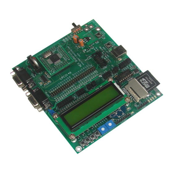
INTRODUCTION Board Features LPC2148 Pro Development Board is a powerful development platform based on LPC2148 ARM7TDMI microcontroller with 512K on-chip memory. This board is powered by USB port and does not need external power supply. It is ideal for developing embedded applications involving high speed wireless communication (Zigbee / Bluetooth / WiFi), USB based data logging, real time data monitoring and control, interactive control panels etc. - Page 5 2x16 Character Alphanumeric • Schematics and Application • examples in KEIL provided in the documentation CD Kit Contains: 1-LPC2148 Pro Development Board 1-USB Cable 1-DB9 Serial Cable A set of 10 1-1 cables Documentation CD contains: I. Schematic II. Programming Software III.
-
Page 6: Lpc2148 Pro Development Board Overview
CPU operating voltage range of 3.0 V to 3.6 V (3.3 V +- 10 pct) with 5 V tolerant I/O • pads. LPC2148 Pro Development Board Overview 1. LPC2148 Plug-in module 11. Jumpers for LCD interface 2. 3V cell holder for RTC 12. -
Page 7: Power Supply
Slide the power switch to ON position to turn the board ON. The red LED will glow indicating that the board is powered. Warning: Please make sure that the USB port on your PC or any other device is capable to source at least 400mA current. NEX Robotics Pvt. Ltd. www.nex-robotics.com... -
Page 8: In System Programming Via Uart0
3. The board enters bootloader mode when BOOT switch is held down at the time of RESET. To enter the bootloader mode, keep the BOOT switch pressed and then press and release RESET switch. You can release the BOOT switch after reset. NEX Robotics Pvt. Ltd. www.nex-robotics.com... -
Page 9: Keil Μvision4 Ide
Keil µVision welcome screen will appear. Please read the instructions on the welcome window and click Next>> to start the installation. Please read the license agreement carefully. If it is acceptable click the check box and click Next>> to continue. NEX Robotics Pvt. Ltd. www.nex-robotics.com... - Page 10 LPC2148 DEVELOPMENT BOARD Select the destination folder where setup will install files. It is always recommended to select the default location. To create backup of old installation select the backup option and click Next>> to continue. NEX Robotics Pvt. Ltd. www.nex-robotics.com...
- Page 11 LPC2148 DEVELOPMENT BOARD In the next window enter your information and click Next>> to continue. On clicking next the file copying process will begin. Wait till setup is complete. NEX Robotics Pvt. Ltd. www.nex-robotics.com...
-
Page 12: Using Flash Magic Tool
To install Flash Magic, Go to “Software” folder in the documentation CD and locate “FlashMagic.exe” file. Click on “FlashMagic.exe” to start the installation process. Once the installation process is started Flash Magic welcome screen will appear. NEX Robotics Pvt. Ltd. www.nex-robotics.com... - Page 13 Please read the license agreement carefully. If it is acceptable click the radio button and click Next>> to continue. Select the destination folder and click Next> to continue. In the next window choose the appropriate folder and click Next> to continue. NEX Robotics Pvt. Ltd. www.nex-robotics.com...
- Page 14 LPC2148 DEVELOPMENT BOARD Select the desired option and click Next> to continue. Setup is now ready to begin installing flash magic. Click Install to continue. NEX Robotics Pvt. Ltd. www.nex-robotics.com...
- Page 15 LPC2148 DEVELOPMENT BOARD Wait till setup installs Flash Magic on your computer. NEX Robotics Pvt. Ltd. www.nex-robotics.com...
- Page 16 LPC2148 DEVELOPMENT BOARD Click Finish to complete the installation process NEX Robotics Pvt. Ltd. www.nex-robotics.com...
-
Page 17: Overview Of Keil Μvision4 Ide
Editor - It is the area where .c and .h files of the project are edited. Project Explorer- It shows the project tree. Output Window- This window shows the messages related to compiling, project building and debugging. NEX Robotics Pvt. Ltd. www.nex-robotics.com... -
Page 18: Create A Project In Keil For Lpc2148 Development Board
2.3.1 Create a Project in Keil for LPC2148 development board 1. To create a new project, Select Project>New uVision Project from the main menu. 2. Create a new directory and name it as First_Project. Click open to enter in to this directory. NEX Robotics Pvt. Ltd. www.nex-robotics.com... - Page 19 LPC2148 DEVELOPMENT BOARD 3. Inside this directory create a new project and name it as First_Project and click Save to continue. 4. In the next window locate NXP (founded by Philips) tree and expand it. NEX Robotics Pvt. Ltd. www.nex-robotics.com...
- Page 20 5. Now select target device as LPC2148 and click OK to continue. 6. Click Yes to copy Startup.s file to project folder. This file configures stack, PLL and maps memory as per the configurations in the wizard. It is discussed in the later sections. NEX Robotics Pvt. Ltd. www.nex-robotics.com...
- Page 21 LPC2148 DEVELOPMENT BOARD 7. Observe the project explorer area in the main window. 8. Now click Project>Manage>Components, Environments, Books from the main menu to ensure compiler settings. NEX Robotics Pvt. Ltd. www.nex-robotics.com...
- Page 22 9. In the Folders/Extensions tab ensure the compiler settings are as shown in the fig. below. If you have installed keil software at a different location then change Tool Base Folder location. Click OK to continue. 10. Now click File>New to create a new file. NEX Robotics Pvt. Ltd. www.nex-robotics.com...
- Page 23 Save to continue. 12. Now add “main.c” to the source group by right clicking on the Source Group 1 from the project explorer and select the highlighted option as shown in the fig. below. NEX Robotics Pvt. Ltd. www.nex-robotics.com...
- Page 24 LPC2148 DEVELOPMENT BOARD 13. Select “main.c” file to be added and click ADD to continue. 14. Observe that “main.c” file is added to the source group in the project explorer window. NEX Robotics Pvt. Ltd. www.nex-robotics.com...
- Page 25 LPC2148 DEVELOPMENT BOARD 15. Right click Target1 in the project explorer window and select the highlighted option as shown in the fig. below. 16. In the appearing window select Target tab and set Xtal. frequency as 12MHz. NEX Robotics Pvt. Ltd. www.nex-robotics.com...
- Page 26 LPC2148 DEVELOPMENT BOARD 17. In the Output tab ensure that Create HEX File option is selected. 18. In the Linker tab ensure that the highlighted option is selected and click OK to continue. NEX Robotics Pvt. Ltd. www.nex-robotics.com...
- Page 27 // Enable GPIO on all pins PINSEL1 = 0x00000000; IO1DIR = (1<<19) | (1<<18) | (1<<17) | (1<<16); // Set P1.16, P1.17, P1.18, P1.19 as Output while(1) LED1_ON(); Delay(25); LED1_OFF(); LED2_ON(); Delay(25); LED2_OFF(); LED3_ON(); Delay(25); LED3_OFF(); LED4_ON(); Delay(25); LED4_OFF(); return(0); NEX Robotics Pvt. Ltd. www.nex-robotics.com...
- Page 28 LPC2148 DEVELOPMENT BOARD 20. Now build the project by clicking on Rebuild button on the main toolbar. 21. You can alternatively build project by clicking on Project>Build Target from the main menu. NEX Robotics Pvt. Ltd. www.nex-robotics.com...
-
Page 29: Code Walkthrough
LPC2148 user manual for more information on GPIO. void Delay(unsigned char j) unsigned int i; for(;j>0;j--) for(i=0; i<60000; i++); function is used to provide some finite delay between Led Delay(unsigned char j) ON and OFF events. NEX Robotics Pvt. Ltd. www.nex-robotics.com... - Page 30 The next step is to load the hex file in to the microcontroller using Flash magic utility. 1. Click Start>Programs>Flash Magic>Flash Magic to start Flash Magic utility. 2 . Click Select Device to select LPC2148 microcontroller. NEX Robotics Pvt. Ltd. www.nex-robotics.com...
- Page 31 LPC2148 DEVELOPMENT BOARD 3. Expand the ARM7 tree and select LPC2148 from the displayed list of microcontrollers. NEX Robotics Pvt. Ltd. www.nex-robotics.com...
- Page 32 4. After selecting the microcontroller, select the COM port that you are going to use and ensure that other settings are as shown in the figure below. 5. To select the hex file click Browse and point to the folder that was created earlier and select the hex file. NEX Robotics Pvt. Ltd. www.nex-robotics.com...
- Page 33 8. Observe the status bar at the bottom of the Flash Magic tool. Wait for the “Finished” status and press “Reset” on the LPC2148 development board and observe the LEDs. If not successful then repeat again from step 6. NEX Robotics Pvt. Ltd. www.nex-robotics.com...
-
Page 34: Configuring Startup.s File Using Configuration Wizard
To do this setting refer step 18 in section 2.3.1. 1. In the Project explorer double click on “startup.s” file. The startup.s file will open up as assembly file. To open the wizard click Configuration Wizard as shown in figure below. NEX Robotics Pvt. Ltd. www.nex-robotics.com... - Page 35 The default setting for MSEL is 5 and for PSEL it is 2. So the core frequency (FCLK) is 60MHz. To change any setting just click on it and make use of the up/down arrows. NEX Robotics Pvt. Ltd. www.nex-robotics.com...
- Page 36 ¼ of CPU clock or ½ of CPU clock or equal to CPU clock. For other settings please refer LPC2148 microcontroller user manual. After you have done using configuration wizard rebuild the project. NEX Robotics Pvt. Ltd. www.nex-robotics.com...
-
Page 37: Using Uvision Debugger In Simulator Mode
To use Debugger in simulator mode first we need to setup the debugger so as to use simulator. 1. Right click Target 1 and select the highlighted option as shown in the figure below. 2. In the debug tab make sure that the highlighted settings are done. Click OK to continue. NEX Robotics Pvt. Ltd. www.nex-robotics.com... - Page 38 Alternatively you can press Ctrl+F5 to toggle between starting and stopping of debug session. 4. Click OK to continue. 5. Go to Peripherals>System Control Block>Phase Locked Loop 0 to observe the PLL settings on the microcontroller. NEX Robotics Pvt. Ltd. www.nex-robotics.com...
- Page 39 It also ensures that PLL settings that we had done in the configuration wizard of the startup code are properly working. 7. Now click Peripherals>Pin Connect Block to include pin connect block, NEX Robotics Pvt. Ltd. www.nex-robotics.com...
- Page 40 9. Arrange the windows as shown in figure below. 10. Now use Step function to step through the code. Alternatively you can press Ctrl+F11. Observe the changes in the Pin connect block and Port1 block as you step through the code. NEX Robotics Pvt. Ltd. www.nex-robotics.com...
- Page 41 11. When you encounter the delay function you can simply use Step Out function. It will execute the delay function and take execution to the next line immediately after the delay function. 12. Now press the Reset button to Reset the CPU and observe the PLL window. NEX Robotics Pvt. Ltd. www.nex-robotics.com...
- Page 42 GPIO and pin connect block vales are also reset. 14. Now let us setup a break point at line no. 25 i.e. at the beginning of the main function. It will halt the execution when the debugger encounters this line. NEX Robotics Pvt. Ltd. www.nex-robotics.com...
- Page 43 16. After clicking on RUN observe the change in the CCLK field. The execution has also halted at the breakpoint that was setup earlier. Now again if you click Run the code will continue to execute. NEX Robotics Pvt. Ltd. www.nex-robotics.com...
-
Page 44: Main Expansion Header
3.3V supply which can be utilised to power external devices. When using the expansion header, it is necessary to disconnect the on-board peripherals connected to these pins by removing the jumpers which links these pins to the on-board peripherals. Refer following sections for jumper settings. NEX Robotics Pvt. Ltd. www.nex-robotics.com... -
Page 45: Leds
When a switch is pressed it will pull the associated pin to logic ‘0’. Port pins P0.15 and P0.30 features alternate function of external interrupts. Jumper SW1 is associated with switch SW1 and so on. NEX Robotics Pvt. Ltd. www.nex-robotics.com... -
Page 46: Lcd Interface
IR RECEIVER There is a TSOP1738 IR receiver on LPC2148 development board. The jumper position is as shown in the above figure. Alternatively IR receiver can be connected to any port pin using 1-1 cable. NEX Robotics Pvt. Ltd. www.nex-robotics.com... -
Page 47: Trimpots
UART1 is selected for RS-232 serial communication. SPI INTERFACE The LPC2148 microcontroller features 2 SPI interfaces i.e. SPI0 and SPI1. On LPC2148 development board SPI0 is used for interfacing SD/MMC card. The SPI expansion NEX Robotics Pvt. Ltd. www.nex-robotics.com... -
Page 48: I2C Interface
The cathode of LED is connected to the pin named as ‘1’ on Driver header and I/O pin connected is connected to pin named as ‘1’ on Logic header by placing a jumper in its position. NEX Robotics Pvt. Ltd. www.nex-robotics.com... -
Page 49: L293D
Fig. 3.7b If jumper positions are as shown in fig. 3.7a, PWM channels 4 & 6 are selected as source of velocity signal. If jumper position are as shown in fig. 3.7b, +5V is selected. NEX Robotics Pvt. Ltd. www.nex-robotics.com... -
Page 50: Jtag Port
VPB clock. It also has a dedicated power supply pin that can be connected to a battery or to the board supply of 3.3V. LPC2148 development board has battery holder for providing battery back up to the internal RTC. NEX Robotics Pvt. Ltd. www.nex-robotics.com... -
Page 51: Sample Programs
To see the result, press any switch and observe the corresponding LED glow. 4.3 BUZZER Hardware Setup: Insert SW4 Jumper. Insert Buzzer Jumper Load the BUZZER.hex file from LPC2148>codes>BUZZER folder using flash magic on the microcontroller flash memory. NEX Robotics Pvt. Ltd. www.nex-robotics.com... -
Page 52: Lcd Interfacing
Load the LCD_INTERFACING.hex file from LPC2148>codes>LCD INTERFACING folder using flash magic on the microcontroller flash memory. Description:After loading the hex file, press reset switch. This application code demonstrates LCD interface on LPC2148 development board. LCD will display “Nex Robotics ARM LPC2148”. 4.5 UART0 COMM (9600 bps) Hardware Setup: Connect a DB9 cable between PC and UART0. -
Page 53: Adc
On reset, microcontroller will write 16 bytes of DATA on the EEPROM 24LC04 and read back the same data. The read data is then sent to UART0, which can be observed on the receive window of terminal software. NEX Robotics Pvt. Ltd. www.nex-robotics.com... -
Page 54: Sd Mmc Interface
Description: This application code demonstrates SD/MMC interface on SPI bus. On reset microcontroller writes a string of data as “ NEX ROBOTICS” on the memory card and reads back the same data. This data is sent to UART0, which can be observed on receive window of terminal software. -
Page 55: Rtc Uart0
Enable terminal to receive data in string format. After loading the hex file, press reset switch. on microcontroller board, The microcontroller board will send the below message, which can be observed on the receive window of terminal software on PC, where the Xbee USB module is connected, NEX Robotics Pvt. Ltd. www.nex-robotics.com... -
Page 56: Board Demo
LPC2148 DEVELOPMENT BOARD “ Nex Robotics PVT LTD ARM7LPC214x Development Board Communication Test Send any character to continue” As instructed in the last line of the above message, please type any character in transmit window of terminal software. This character is received by the development board via Xbee module present on board. - Page 57 LPC2148 DEVELOPMENT BOARD References Volume 1: LPC214x User manual AN10406-Accessing SD/MMC card using SPI on LPC2000 AN10404-Initialization code/hints for the LPC2000 family AN10331-Philips LPC2xxx family phase lock loop SanDisk SD Card Product Manual NEX Robotics Pvt. Ltd. www.nex-robotics.com...
Need help?
Do you have a question about the LPC2148 Pro and is the answer not in the manual?
Questions and answers