
Related Manuals for VORAGO REB1

Summary of Contents for VORAGO REB1
- Page 1 REB1 USER MANUAL Evaluation board for VA108x0 MCU from VORAGO FEBRUARY 10, 2017 VORAGO TECHNOLOGIES...
-
Page 2: Table Of Contents
Contents Introduction ..........................2 Purpose of Document ..................... 2 Overview of Hardware and Software components ............2 REB1 board component placement diagram ..............3 Connector pin assignment table ..................3 Materials List ........................4 Support..........................4 Software Setup ........................4 Required Downloads ....................... -
Page 3: Introduction
1 Introduction 1.1 Purpose of Document This document is intended to provide instructions on how to use all features of the REB1 evaluation board and provide a working platform for software development with either the VA10800 or VA10820 MCUs from VORAGO. The VA10820 has supplemental EDAC (error detection and correction) and memory scrub functionality. -
Page 4: Reb1 Board Component Placement Diagram
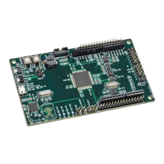
Figure 2 - Photo of REB1 with functional blocks identified 1.4 Connector pin assignment table The schematic for the board is one of the included files in the REB1 software download package. To assist with quickly finding which pins are tied to the various connectors on the... -
Page 5: Materials List
VA10800/VA10820 Evaluation Board User’s Manual V3.0 Table 1 - REB1 Connector designations 1.5 Materials List • REB1 evaluation board – Programmed with demonstration program • 36” Micro USB cable • Insert card with component placement picture and URL • 7 jumpers. -
Page 6: Required Downloads
Three IDE options are provided. Only one IDE is needed. Please download one IDE, the Segger J-Link software and the VORAGO REB1 software development code as outlined in the below sections. - Page 7 VA10800/VA10820 Evaluation Board User’s Manual V3.0 Please use the default directories for the “core” and “pack” when prompted for information during the install. Before the MDK install is complete, the pack installer dialogue will open. Let it run to completion and then close it. The va108xx.pack will be loaded later when we open the project. 2.1.2 IAR Embedded Systems for ARM IDE Visit https://www.iar.com/iar-embedded-workbench/#!?currentTab=free-trials...
- Page 8 VA108xx.svd (contains all register definitions for the device) UMI2_va108xx_EE.s32 (programming file that the iTAG50 tools uses to program the SPI EE on the REB1 board. VA108xx.json (contains debug interface specifics for a device) If these files are not present, please copy and paste them from the iSystem project folder.
- Page 9 2.1.4 Segger J-Link https://www.segger.com/jlink-software.html Select Software and documentation pack for Windows V6.10n [23,162 KB]. If a later version is available, please use it. 2.1.5 VORAGO Software and Documentation http://voragotech.com/REB1. This will have the following components in a single .zip file:...
-
Page 10: Hardware Check
Clock source jumper (J18) o MCU voltage supply shunts (J2 & J20) • Connect the USB cable between PC and the REB1 board o The D_3V3 LED will indicate that power is applied. o D1 will indicate that the J-Link OB enumerated and has successfully connected to the VA108x0 device. - Page 11 VA10800/VA10820 Evaluation Board User’s Manual V3.0 A populated Keil project is available in the ../software/mcu/project/reb1_va108xx_Keil folder as shown here. Double click on the file ending with uvprojx and the Keil IDE should open with this project loaded. The screen should look like the figure below.
- Page 12 From the Project pull-down menu, select “manage” and then “pack installer”. This will open another window. From the pack installer window, Use the “file” pull-down menu and select “import”. Navigate to the VA108xx1.0.0.pack file which was part of the VORAGO download and hit the Open button.
- Page 13 MCU and JTAG debugger probe. The following sections provide the minimum options for the VORAGO software development kit to function. All the options can be accessed under the Project pull-down menu as shown here. An...
- Page 14 The Keil IDE supports many forms of JTAG interfaces. The default debug connection is the ULINK2 from Keil. The REB1 board has a built in JTAG interface called Segger J-Link OB. The IDE must be told which JTAG interface is used. See below for screen captures on how to do this.
- Page 15 VA10800/VA10820 Evaluation Board User’s Manual V3.0 Second, set the J-Link to use the JTAG connection. Click the Settings button and select “JTAG” in the Port Window. The “Max Clock” selection can be anything up to 5 MHz. The board should be connected to a PC prior to setting up the Debugger.
- Page 16 ARM CoreSight JTAG-DP, the other is the test chain for the device. 4.1.5 Select device If the Vorago.VA108xx.vers.pack file has been imported, the VA108x0 will be shown under the generic group. The memory map for the VA10800 is a subset of the VA10820 and only one...
- Page 17 VA10800/VA10820 Evaluation Board User’s Manual V3.0 4.1.6 Project Build The Keil tool has several ways to access many functions. There is always a pull-down menu available but many functions have hot keys or icons that can be clicked on. To compile and link the entire project, the “Rebuild all target files”...
- Page 18 VA10800/VA10820 Evaluation Board User’s Manual V3.0 Once the IDE has entered debug mode, the screen appearance will resemble the following image. Many options are available under the debug menu as shown here. Most of these functions have buttons on the menu bar for quick point and click access. If the demonstration program has been loaded, the Run button can be pressed to begin code execution.
-
Page 19: Iar Ewarm Ide
4.2 IAR EWARM IDE – 4.2.1 Opening a project The BSP download from VORAGO has a file structure as outlined here. There are several unique files for IAR that are stored inside the reb1_va108xx_IAR folder. Common, driver and utilities folders contain files that work with any IDE. - Page 20 The tool has many configuration options. Only the critical ones are discussed here. The IDE must know which debug pod is being used. Since the REB1 board comes with an on-board Segger debugger, we need to select “J-Link”. Under the Project pull-down menu, select Options and then Debugger.
- Page 21 VA10800/VA10820 Evaluation Board User’s Manual V3.0 4.2.4 Clean and Project Build Before a program can be executed, it must be built which includes compilation and linking. Prior to rebuilding the project, it a good idea to “clean” the workspace which can remove stale files.
-
Page 22: Isystem Winidea Ide
Programming support of SPI memory devices with the VA108xx is only available with the iTAG50 probe which is available from Amazon(amazon.de). 4.3.1 Opening a project The download from VORAGO has a file structure as outlined here. A similar project is available from the iSystem website.: http://www.isystem.com/download/examples. - Page 23 Navigate to the “reb1_va108xx_iSystem -> app -> reb1_reference -> reb1_va108xx” folder and double click “reb1_gcc_jlink.xjrf” (type=WinIDEA workspace). The winIDEA Open IDE will open with the REB1 project preloaded. This project has the target selected to “VA108xx_reb1_Sample” which calls out the va108xx device.
- Page 24 VA10800/VA10820 Evaluation Board User’s Manual V3.0 Although the project should be ready to compile and debug on the REB1 board, it may be necessary to adjust some settings such as the debug connection. Under the Segger pull-down menu, selection Options then fill in the Debug interface field with JTAG.
- Page 25 When a project is downloaded, the file will be loaded to RAM and then the EEPROM will be programmed. A dialog box will show the progress. Pressing the RESET button on the REB1 board will force the MCU to read the EEPROM and load the on-chip RAM then begin executing...
-
Page 26: J-Link Ob And Rtt (Real Time Terminal)
VA10800/VA10820 Evaluation Board User’s Manual V3.0 code. Alternatively, it is still possible to use the RUN, STOP and RESET buttons to control processor activity. 4.4 J-Link OB and RTT (Real Time Terminal) To visually monitor activity in the MCU, we have incorporated code that streams information via the JTAG interface to a PC. -
Page 27: Programming Procedure (Keil Specific)
V3.0 4.4.2 Embedded Software to enable RTT Inside the REB1 demonstration program, there is a series of subroutines provided by Segger to configure the RTT, transmit and receive characters. Inside of this code, buffers are created and the RTT Control Block address is fixed at 0x10007000. - Page 28 VA10800/VA10820 Evaluation Board User’s Manual V3.0 of EEPROM takes only a few seconds. Support for Cypress FRAM, TT Semi Flash and Everspin MRAM is also available. 4.5.1 Utility Options Before programming the EEPROM that boots the VA108xx, the Utilities options menu must be set up.
-
Page 29: Software Development Kit
5 Software Development Kit VORAGO provides a good starting point for end application development with the REB1 SDK (software development kit). This section gives a brief tour of the kit. 5.1 Project organization Inside each IDE, a project can be organized in groups to facilitate re-use of proven components. -
Page 30: Cmsis Compatible Driver
VA10800/VA10820 Evaluation Board User’s Manual V3.0 Figure 4 - Keil IDE project item management folder The “common” group has files specific the MCU. The “driver” group has files for using the peripheral modules of the VA108xx MCU. The “custom” group has files unique for this project including the main.c file. -
Page 31: Preprocessor Directives
A separate set of documentation in Doxygen format is available with the REB1 download in the documentation folder. Navigate to the “index.html” file and double click on it to access the Doxygen information for the board and software. - Page 32 VA10800/VA10820 Evaluation Board User’s Manual V3.0 Second, the main routine (inside file reb_main.c) should be opened and some code added. If not already open, please double click on the demonstration project, ../software/mcu/project/reb1_va108xx. Navigate to a section of the code around line 58 that already sets up the port pin for driving LED2.
-
Page 33: Lab2 - Advanced Input Pin Filtering And Debounce Of Switch Input
VA10800/VA10820 Evaluation Board User’s Manual V3.0 cnt_100msec = 0 ; // reset counter VOR_GPIO->BANK[0].TOGOUT |= (1 << PORTA_6_D4); Compile, download and run the program. 6.2 LAB2 - Advanced input pin filtering and debounce of switch input. The VA108xx comes with advanced filtering schemes to eliminate glitches being read and wasting CPU time filtering them out. -
Page 34: Other Resources For Va108X0 Code
VOR_UART->BANK[0].CLKSCALE = 0x5161; // baud rate = 50Mhz / VOR_UART->BANK[0].ENABLE = 2 ; // only enable TX = bit position 1. VOR_UART->BANK[0].DATA = 0x5A ; // send single byte out. 8 Other resources for VA108x0 code Vorago application notes: http://www.voragotech.com/resources Revision history 1.0 April 2016 2.0 November 2016... - Page 35 VA10800/VA10820 Evaluation Board User’s Manual V3.0 3.0 February 2017 3.1 Updated iSystem section for latest release. 3.2 Added text to show how to switch from RTT to UART logging 3.3 Removed section with workaround for SVD formatting error message. (No longer needed) 3.4 Added two new Frequently asked questions in section 7.
Need help?
Do you have a question about the REB1 and is the answer not in the manual?
Questions and answers