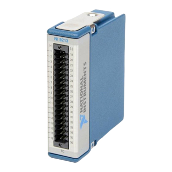
National Instruments NI-9213 Getting Started
Hide thumbs
Also See for NI-9213:
- Getting started manual (23 pages) ,
- Getting started (11 pages) ,
- Getting started manual (19 pages)
Table of Contents
Advertisement
Quick Links
Advertisement
Table of Contents

Summary of Contents for National Instruments NI-9213
- Page 1 NI-9213 Getting Started 2023-04-19...
- Page 2 NI-9213 Getting Started Contents NI 9213 Getting Started Guide Map..........3...
-
Page 3: Safety Guidelines
NI-9213 Getting Started NI 9213 Getting Started Guide Map Overview This document explains how to connect to the NI 9213. Note Before you begin, complete the software and hardware installation procedures in your chassis documentation. Note The guidelines in this document are specific to the NI 9213. -
Page 4: Hazardous Voltage
NI-9213 Getting Started Hazardous Voltage This icon denotes a warning advising you to take precautions to avoid electrical shock. Safety Voltages Connect only voltages that are within the following limits: Between any two terminals ±30 V maximum Isolation Channel-to-channel None... - Page 5 NI-9213 Getting Started Caution Ensure that hazardous voltage wiring is performed only by qualified personnel adhering to local electrical standards. Caution Do not mix hazardous voltage circuits and human-accessible circuits on the same module. Caution Ensure that devices and circuits connected to the module are properly insulated from human contact.
- Page 6 NI-9213 Getting Started Caution For Division 2 and Zone 2 applications, install the system in an enclosure rated to at least IP54 as defined by IEC/EN 60079-15. Caution For Division 2 and Zone 2 applications, connected signals must be within the following limits.
-
Page 7: Electromagnetic Compatibility Guidelines
Furthermore, any changes or modifications to the product not expressly approved by National Instruments could void your authority to operate it under your local regulatory rules. Special Conditions for Marine Applications Some products are Lloyd’s Register (LR) Type Approved for marine (shipboard) -
Page 8: Preparing The Environment
NI-9213 Getting Started Preparing the Environment Ensure that the environment in which you are using the NI 9213 meets the following specifications. Operating temperature -40 °C to 70 °C (IEC 60068-2-1, IEC 60068-2-2) Operating humidity (IEC 60068-2-78) 10% RH to 90% RH, noncondensing... -
Page 9: Connecting A Thermocouple
NI-9213 Getting Started Table 1. Signal Descriptions Signal Description Common reference connection No connection Positive thermocouple connection Negative thermocouple connection Connecting a Thermocouple You can connect a shielded thermocouple to the NI 9213. Figure 1. Connecting a Thermocouple to the NI 9213... - Page 10 NI-9213 Getting Started 1. Insert the screwdriver into a spring clamp activation slot to open the corresponding connector terminal. 2. Press a wire into the open connector terminal. 3. Remove the screwdriver from the activation slot to clamp the wire into place.
-
Page 11: Overvoltage Protection
NI-9213 Getting Started Allow the thermal gradients to settle after a change in system power or ■ in ambient temperature. A change in system power can happen when the system powers on, the system comes out of sleep mode, or you insert/remove modules. - Page 12 1 866 ASK MYNI (275 6964). For telephone support outside the United States, visit the Worldwide Offices section of ni.com/niglobal to access the branch office websites, which provide up-to-date contact information, support phone numbers, email addresses, and current events. ni.com © 2023 National Instruments Corporation.


Need help?
Do you have a question about the NI-9213 and is the answer not in the manual?
Questions and answers