Table of Contents
Advertisement
Advertisement
Table of Contents

Related Manuals for RHINO 832


Summary of Contents for RHINO 832
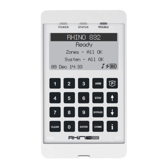
- Page 1 RHINO 832 Ready Zones - All OK System - All OK 09 Dec 14:33...
- Page 2 V1.4 13 October 2021...
-
Page 3: Table Of Contents
CONTENTS General Overview ........................4 Rhino 832 Panel Overview ................................Introduction ......................................Features ........................................Remote keypads ....................................Wireless devices ....................................Upload/download software ................................Installation Sequence ......................Getting Started ......................... 8 Control panel layout ..................................PCB Layout ......................................Connecting devices to the network............................ -
Page 4: General Overview
GENERAL OVERVIEW Rhino 832 Panel Overview LCD Keypad LCD Keypad RHINO 832 RHINO 832 Ready Ready Zones - All OK Zones - All OK System - All OK System - All OK 09 Dec 14:33 09 Dec 14:33 Up to 4 keypads... -
Page 5: Introduction
Low battery monitoring 3. Remote Keypads The Rhino 832 panel will accept up to a maximum of 4 remote Graphic LCD keypads. All remote keypads require a 4-wire connection to the control panel using standard alarm cable. The Graphic LCD keypad features a 128 x 64 pixel display on which all zone, area and system statuses are displayed. -
Page 6: Wireless Devices
A module used to extend the range of wireless devices. 5. Upload/download Software Rhino UDL is a Windows® based software package that can be used to remotely or locally program and diagnose the Rhino range of security systems. Features include:... -
Page 7: Installation Sequence
USB connection or remotely via the FSK Gateway. 8: Test the System Test the system thoroughly and perform the zone commissioning procedure on page 40 for wireless zones, to ensure all features and functions are operating as required. Rhino 832 Installation Manual... -
Page 8: Getting Started
R102 JTAG1 WIRELESS GSM2 ELECTRONICS SA (PTY) LTD AP Rhino832 PCB ISSUE C R101 R118 D10 C39 C40 D7 R45 R105 R111 R112 PROG R B G Y Z1 Z4Z5 Z7 C Z8 AC AC KEYPAD/BUS Rhino 832 Installation Manual... -
Page 9: Pcb Layout
R111 R112 R105 PROG R B G Y Z1 AC AC Z4Z5 Z7 C Z8 KEYPAD/BUS 1. AC Terminals The three wires from the transformer are connected to these terminals to supply power to the system. Rhino 832 Installation Manual... - Page 10 Panel outputs 1 and 2 default to bell and strobe operation, but can be programmed for other functions if required. See page 33 for programming details. 6. USB Connection A micro USB port is used for local connection to Rhino UDL and/or firmware updating software from a Windows PC. 7. Run LED Flashes when the panel is powered and operational.
-
Page 11: Connecting Devices To The Network
fixing. Installing the expanders 8-zone wired expander This expander is plugged into the connector of the Rhino 832 PCB as shown on the PCB Layout on page 9. 16-zone wired expander The external 16-zone expander connects to the same network terminals as the keypads. These are located at the bottom left hand corner of the control panel. -
Page 12: Installing The Keypads
When a power supply is installed, the 0V connections on the power supply must be connected through to 0V on the control panel and the +12V connection between the control panel and the device must be disconnected (see figure on next page). Rhino 832 Installation Manual... -
Page 13: Setting Up The Zones
This wiring configuration should be used when connecting detection devices that only have a normally open alarm output. Connect the detector as shown below and ensure that the zone is programmed for normally open operation. See page 25. Rhino 832 Installation Manual... - Page 14 This wiring configuration should be used when connecting detection devices that have a normally closed alarm and tamper output. Connect the detector as shown below and ensure that the zone is programmed for "Double EOL" operation. See page 25. Rhino 832 Installation Manual...
-
Page 15: Wireless Zones
E.O.L Detector Wireless Zones The Rhino 832 has a wireless transceiver that is plugged onto the main PCB. It allows support for various wireless devices. The following wireless devices are compatible with the Rhino 832 panel. RH-100 Wireless Door Contact The RH-100 is a professional state-of-the-art wireless door contact sensor. - Page 16 The RH-101 is a third party wireless interface. When wired to a third party PIR device, it will provide wireless connectivity from the device to the Rhino 832 alarm panel. The RH-101 has a normally closed alarm input as well as a normally closed tamper input. The tamper contact is also wired in series with the internal tamper switch.
- Page 17 The RH-200 indoor PIR has a built-in wireless transceiver for direct communication to the Rhino 832 panel. The PIR should be allocated to one of the available zones (1-32). When a zone has been programmed as a wireless zone, it cannot function as a wired zone anymore (the wired input is disabled).
- Page 18 The Raptor gate module must be allocated to one of the available zones (1-32). When a zone has been programmed as a wireless zone, it cannot function as a wired zone anymore (the wired input is disabled). Refer to the in-box leaflet for more information. Rhino 832 Installation Manual...
- Page 19 Refer to the Raptor Remote Control product manual for more information. 1. Panic alarm This button activates the panic alarm. 2. Away arm This button away arms the areas allocated to the user. 3. Disarm This button disarms the areas allocated to the user. Rhino 832 Installation Manual...
-
Page 20: Other Wiring
LEDs, sounders or relays etc. See page 33 for details on programming outputs. Each panel output is rated at 1 Amp and switches to 0V when active. The figure below shows some wiring examples: Control Panel cathode anode LED Indicator Rhino 832 Installation Manual... -
Page 21: Applying Power To The Control Panel
PCB will flash and the 7 segment display with display the status of the GSM modem. If the system enters into an alarm condition, enter the default master user code 5678. The alarm tone will then stop. Rhino 832 Installation Manual... -
Page 22: Programming
All the configuration menus have the same, easy to navigate structure: Menu 01: OPTION 1 02: OPTION 2 03: OPTION 3 04: OPTION 4 05: OPTION 5 06: OPTION 6 Press the keys to scroll through the menu options Rhino 832 Installation Manual... -
Page 23: Zone Options
05 Perimeter This zone type is used for external detection devices. Activation of this zone will cause the system to go into a full alarm condition when the relevant area is armed. Rhino 832 Installation Manual... - Page 24 This zone type operates as stay 1 arm key, but performs a stay 3 arm operation. Zone types 06 to 11 will cause an alarm even when the system is disarmed. 02 Wiring 01 Normally Closed The detector contact is normally closed and opens when activated. Rhino 832 Installation Manual...
-
Page 25: Programming Wireless Zones
To manually program the wireless serial, enter the wireless device's serial number. Enter the code that appears after the 0x written next to ‘ID’ on the label e.g. 00027A59. See Appendix A on page 47 for the Hex Entry Mode. Rhino 832 Installation Manual... - Page 26 The serial number for the wireless device can be confirmed by viewing the printed sticker at the back of the wireless device. 06 Attributes Each zone can be programmed with optional attributes for additional functionality. Note that this icon ( ) appears next to the option if it is enabled. Rhino 832 Installation Manual...
- Page 27 When disabled and if the zone type is a keyswitch type, the operation remains as latching mode. 07 Areas The Rhino 832 alarm panel has 4 areas and these allow the system to be divided into 4 different areas of protection. Each area can be armed and disarmed independently from each other. By default, all zones are assigned to area 1, but if required, a zone can be assigned to any of the available areas.
- Page 28 02 Tone 1 Chime tone 1 sounds when the zone is activated. 03 Tone 2 Chime tone 2 sounds when the zone is activated. 04 Tone 3 Chime tone 3 sounds when the zone is activated. Rhino 832 Installation Manual...
-
Page 29: Area Options
Area Options 1 This icon ( ) will appear next to the option that is enabled. See example below: Area 01 OPTIONS1 AC OFF ARM PULSE STROBE ARM 0: DISABLE 1: ENABLE UP/DOWN: SELECT ENTER: SAVE CLEAR: CANCEL Rhino 832 Installation Manual... - Page 30 If enabled, the selected area is automatically armed by Control Timer 1. If disabled, the selected area is not armed automatically. 02 Arm with Control Timer 2 If enabled, the selected area is automatically armed by Control Timer 2. Rhino 832 Installation Manual...
- Page 31 If disabled, the selected area is not disarmed automatically. 03 Disarm with Control Timer 3 If enabled, the selected area is automatically disarmed by Control Timer 3. If disabled, the selected area is not disarmed automatically. Rhino 832 Installation Manual...
-
Page 32: Hardware Options
This is the local time zone (used for the date and time). For example, in South Africa the time zone is GMT +2. 03 Hardware 01 General Volume This is the tone volume on the keypad. Values range between 0 (off) and 10 (loudest). Default = Rhino 832 Installation Manual... - Page 33 If disabled, the bell tamper input is not monitored. 04 Configuration This icon ( ) will appear next to the option that is enabled. Configuration CONFIGURATION RESTORE BYPASSED 0: DISABLE 1: ENABLE UP/DOWN: SELECT ENTER: SAVE CLEAR: CANCEL Rhino 832 Installation Manual...
- Page 34 05 Control Timers The Rhino 832 has seven programmable Control Timers. Each timer has a switch on time (On Time), switch off time (Off Time) and days of operation for both the on and off times. Control Timer can be used to automatically arm or disarm the system.
- Page 35 This option scans the bus for new devices for example a keypad, expander, etc. The bus scan option enables new bus devices to be supervised by the panel. 07 Default Panel This is the section where the panel can be defaulted to its factory settings. Rhino 832 Installation Manual...
-
Page 36: Keypad Options
04 Keypad Options This section covers programming of the remote keypads. Up to 4 keypads can be connected to the Rhino 832 alarm panel. 01 Keypad Options 1 These options control the functionality of the keys on the keypad. This icon ( ) will appear next to the option that is enabled. -
Page 37: Outputs
Output 1 01: TYPE 02: SUB TYPE 03: OPTIONS 04: AREAS 05: WIRING 06: TEXT 01 Type The output should have one of the following types: 01 Global Where the output is controlled by the panel, or Rhino 832 Installation Manual... - Page 38 'Remote Control XX' where 'XX' is the output number. For example, if Output 16 is programmed as a remote controlled output, the panel will automatically set it up as Remote Control 16. 03 Options This icon ( ) will appear next to the option that is enabled. Rhino 832 Installation Manual...
- Page 39 Wired outputs use 4 available onboard outputs on the panel. By default, these outputs switch to ground when activated. 02 Wireless Module Wireless outputs work with the wireless bi-directional gate module (digital I/O). Up to 32 wireless outputs can be programmed on the Rhino 832 panel. Rhino 832 Installation Manual...
-
Page 40: Communications
Contact ID protocol. 02 Reported Events This section selects which groups of events are reported to the ARC. This icon ( ) will appear next to all options that are enabled. Rhino 832 Installation Manual... - Page 41 03 UDL Password The UDL password provides communication security with the remote UDL software. The UDL password in the control panel must match the UDL password configured in the Rhino UDL software package to establish a communication link. Rhino 832 Installation Manual...
-
Page 42: Users
07 Users The Rhino 832 has a total of 21 users. This section covers programming of the users. User 00 is the engineer which has a default code of 1234. User 01 is the master user which has a default code of 5678. - Page 43 The serial number can be confirmed in the wireless serial section. Learn Successful Serial:00083D3C Once all programming has been completed, the system is ready for use. Please ensure the system users are provided with adequate training on operating the alarm system. Rhino 832 Installation Manual...
-
Page 44: Zone Commissioning Process
ZONE COMMISSIONING PROCESS The commissioning mode is a testing mode where the Rhino 832 panel tests the signal strength of wireless zones programmed into the system. The commissioning mode is triggered when adding new wireless zones or changing the zone type of an existing zone to a wireless zone. - Page 45 Front Door is complete. The next zone now needs to be commissioned. Commissioning Number of zone activations required 01: BACK DOOR (3) INFO: PROGRAMMING MENU Commissioning Number of zone activations left 01: BACK DOOR (2) INFO: PROGRAMMING MENU Rhino 832 Installation Manual...
- Page 46 INFO: PROGRAMMING MENU Away Please When all the wireless zones are commissioned successfully, the panel will disable the commissioning procedure, display that the procedure is complete and then go into its normal operation mode. Disabling commission Commissioning Complete Rhino 832 Installation Manual...
- Page 47 RHINO 832 Ready Zones - All OK System - All OK 09 Dec 14:33 Rhino 832 Installation Manual...
-
Page 48: Rhino Upload/Download (Udl)
Click on Accounts Click on Add New Account Enter the customer information for future reference. Select the control panel model: Rhino 832 Enter the Rhino UDL password so that it matches the ones entered into the alarm panel. Rhino 832 Installation Manual... - Page 49 Information fields. To connect to the alarm panel from a remote location, an internet connection is required on the programming computer. To connect to the panel remotely, select Connect via FSK Gateway option on the Connect Menu. Rhino 832 Installation Manual...
- Page 50 The panel can be accessed via USB using a micro USB cable. Connect the USB cable to the PC and the micro USB connector on the panel. Click on the ‘Connect via USB-Link’ option in the Connect Menu to access the panel. Rhino 832 Installation Manual...
-
Page 51: Text Entry Mode
Back one character Advance to the next character Accept the serial number To enter the alphanumeric characters A to F A,B,C are entered by pressing and holding the D,E,F are entered by pressing and holding the Rhino 832 Installation Manual... -
Page 52: Warranty Information
Amecor (Pty) Ltd reserves the right to change specification without prior notice. As the Rhino 832 panel is not a complete intruder alarm system, but only part of it. Amecor (Pty) Ltd does not accept responsibility or liability for any damages whatsoever based on any claim that the unit failed to function correctly. - Page 53 Notes:...
- Page 56 MORE INFORMATION sales@amecor.com www.amecor.com...
Need help?
Do you have a question about the 832 and is the answer not in the manual?
Questions and answers
Display shows Box Tamper
The keypad making a sound and cannot stop
The RHINO 832 keypad makes sounds based on enabled keypad tones, such as alarm tones, trouble tones, chime tones, entry tones, exit tones, or key press tones. To stop the sound, disable the corresponding tone in the keypad settings by selecting the appropriate option and ensuring the icon next to the tone is removed.
This answer is automatically generated
I cant get the external led light to work when armed -Rhino 834 system