Table of Contents
Advertisement
Advertisement
Table of Contents

Related Manuals for Asus ROG STRIX B760-A GAMING WIFI


Summary of Contents for Asus ROG STRIX B760-A GAMING WIFI
- Page 1 ROG STRIX B760-A GAMING WIFI...
- Page 2 Product warranty or service will not be extended if: (1) the product is repaired, modified or altered, unless such repair, modification of alteration is authorized in writing by ASUS; or (2) the serial number of the product is defaced or missing.
-
Page 3: Table Of Contents
Contents Safety information ......................iv About this guide ........................v ROG STRIX B760-A GAMING WIFI specifications summary ........vi Package contents ......................xi Connectors with shared bandwidth ................xii Chapter 1: Product Introduction Before you proceed ..................1-1 Motherboard layout ..................1-2 Chapter 2: Basic Installation Building your PC system .................2-1 2.1.1... -
Page 4: Safety Information
Safety information Electrical safety • To prevent electrical shock hazard, disconnect the power cable from the electrical outlet before relocating the system. • When adding or removing devices to or from the system, ensure that the power cables for the devices are unplugged before the signal cables are connected. If possible, disconnect all power cables from the existing system before you add a device. -
Page 5: About This Guide
Refer to the following sources for additional information and for product and software updates. ASUS website The ASUS website (www.asus.com) provides updated information on ASUS hardware and software products. Optional documentation Your product package may include optional documentation, such as warranty flyers, that may have been added by your dealer. -
Page 6: Rog Strix B760-A Gaming Wifi Specifications Summary
ROG STRIX B760-A GAMING WIFI specifications summary Intel Socket LGA1700 for 13 Gen Intel Core™ & 12 Gen Intel ® ® ® Core™, Pentium Gold and Celeron Processors* ® ® Supports Intel Turbo Boost Technology 2.0 and Intel Turbo Boost Max ®... - Page 7 ROG STRIX B760-A GAMING WIFI specifications summary Wi-Fi 6E 2x2 Wi-Fi 6E (802.11 a/b/g/n/ac/ax) Supports 2.4/5/6GHz frequency band* Wireless & Bluetooth v5.3** ® Bluetooth ® * WiFi 6E 6GHz regulatory may vary between countries. ** The Bluetooth version may vary, please refer to the Wi-Fi module manufacturer’s website for the latest specifications.
- Page 8 ROG STRIX B760-A GAMING WIFI specifications summary Fan and Cooling related 1 x 4-pin CPU Fan header 1 x 4-pin CPU OPT Fan header 1 x 4-pin AIO Pump header 4 x 4-pin Chassis Fan headers Power related 1 x 24-pin Main Power connector...
- Page 9 ROG STRIX B760-A GAMING WIFI specifications summary Aura Sync - Aura RGB header - Addressable Gen 2 headers ROG Exclusive Software - GameFirst VI - ROG CPU-Z - Sonic Studio III + Sonic Studio Virtual Mixer + Sonic Suite Companion...
- Page 10 • Specifications are subject to change without notice. Please refer to the ASUS website for the latest specifications. • MyASUS offers a variety of support features such as helping to troubleshoot issues, optimizing product performance, integrating ASUS software, and recovery drive creation.
-
Page 11: Package Contents
Package contents Check your motherboard package for the following items. Motherboard 1 x ROG STRIX B760-A GAMING WIFI motherboard Cables 2 x SATA 6Gb/s cables Additional Cooling Kit 1 x Thermal pad for M.2 1 x ASUS Wi-Fi moving antennas 1 x Cable ties package 1 x M.2 Q-Latch package... -
Page 12: Connectors With Shared Bandwidth
Connectors with shared bandwidth CPU_FAN AIO_PUMP CPU_OPT ATX_12V_2 ATX_12V_1 HDMI_DP DIGI+ USB_E1234 BIOS_FLBK DRAM FLBK_LED1 BOOT U32G2X2_C1 LAN_U32G2_3 U32G1_E34 LGA1700 M.2(WIFI) AUDIO M.2_1(SOCKET3) PCIE SATA 4.0 X4 2242 2260 2280 Ethernet PCIEX16(G5) BATTERY Intel ® B760 PCIEX1(G3)_1 Super 256Mb BIOS PCIEX16(G3) 2242 2260... -
Page 13: Chapter 1: Product Introduction
• The pin definitions in this chapter are for reference only. The pin names depend on the location of the header/jumper/connector. • For more information on installing your motherboard, please scan the QR code below: ROG STRIX B760-A GAMING WIFI... -
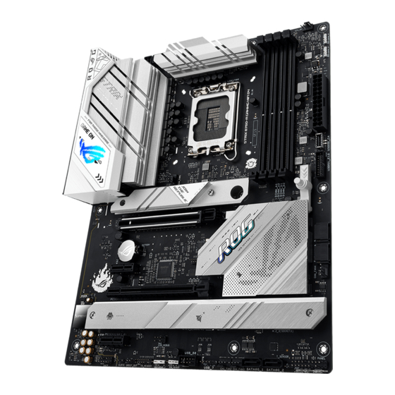
Page 14: Motherboard Layout
Motherboard layout 24.4cm(9.6in) CPU_OPT CPU_FAN AIO_PUMP ATX_12V_2 ATX_12V_1 HDMI_DP DIGI+ USB_E1234 BIOS_FLBK DRAM FLBK_LED1 BOOT U32G2X2_C1 LAN_U32G2_3 U32G1_E34 LGA1700 M.2(WIFI) AUDIO M.2_1(SOCKET3) PCIE SATA 4.0 X4 2242 2260 2280 Ethernet PCIEX16(G5) BATTERY Intel ® B760 PCIEX1(G3)_1 Super 256Mb BIOS PCIEX16(G3) 2242 2260 22110... - Page 15 14. Front Panel Audio header 1-17 15. S/PDIF Out header 1-17 16. System Panel header 1-18 17. Thermal Sensor header 1-19 18. Thunderbolt header 1-19 (USB4 ® 19. BIOS FlashBack™ LED 1-20 20. Q-LEDs 1-20 ROG STRIX B760-A GAMING WIFI...
- Page 16 Contact your retailer immediately if the PnP cap is missing, or if you see any damage to the PnP cap/socket contacts/motherboard components. ASUS will shoulder the cost of repair only if the damage is shipment/ transit-related.
- Page 17 A DDR5 memory module is notched differently from a DDR, DDR2, DDR3, or DDR4 module. DO NOT install a DDR, DDR2, DDR3, or DDR4 memory module to the DDR5 slot. Recommended memory configurations DIMM_A1 DIMM_A2 DIMM_A2 DIMM_A2 DIMM_B1 DIMM_B2 DIMM_B2 ROG STRIX B760-A GAMING WIFI...
- Page 18 (D/C) from the same vendor. Check with the vendor to get the correct memory modules. • Visit the ASUS website for the latest QVL. Chapter 1: Product Introduction...
- Page 19 PCIEX16(G3) PCIEX1(G3)_2 Please refer to the following tables for the recommended VGA configuration. PCIEX1(G3)_1 and PCIEX1(G3)_2 slots share bandwidth with PCIe x16(G3). When PCIEX1(G3)_1 or PCIEX1(G3)_2 slot is operating, PCIEX16(G3) will only support x2 mode. ROG STRIX B760-A GAMING WIFI...
- Page 20 Fan and Pump headers The Fan and Pump headers allow you to connect fans or pumps to cool the system. CPU_FAN AIO_PUMP CPU_OPT FAN PWM CHA_FAN1 FAN IN CHA_FAN4 FAN PWR CHA_FAN2 CHA_FAN3 • DO NOT forget to connect the fan cables to the fan headers. Insufficient air flow inside the system may damage the motherboard components.
- Page 21 The system may become unstable or may not boot up if the power is inadequate. • If you want to use two high-end PCI Express x16 cards, use a PSU with 1000W power or above to ensure the system stability. ROG STRIX B760-A GAMING WIFI...
- Page 22 M.2 slots The M.2 slots allow you to install M.2 devices such as M.2 SSD modules. M.2_1(SOCKET3) M.2_3(SOCKET3) M.2_2(SOCKET3) • Intel ® and 12 Gen Processors: M.2_1 slot (Key M), type 2242/2260/2280 (supports PCIe 4.0 x4 mode) • Intel B760 Chipset: ®...
- Page 23 1, 5, and 10 configuration with the Intel Rapid Storage Technology through the onboard ® Intel B760 chipset. ® Before creating a RAID set, refer to the RAID Configuration Guide. You can download the RAID Configuration Guide from the ASUS website. ROG STRIX B760-A GAMING WIFI 1-11...
- Page 24 USB 3.2 Gen 2 Type-C Front Panel connector ® The USB 3.2 Gen 2 Type-C connector allows you to connect a USB 3.2 Gen 2 ® Type-C module for an additional USB 3.2 Gen 2 Type-C port on the front panel. The ®...
- Page 25 The USB 2.0 headers provide data transfer speeds of up to 480 Mb/s. USB_56 PIN 1 USB_7 PIN 1 DO NOT connect a 1394 cable to the USB connectors. Doing so will damage the motherboard! The USB 2.0 module is purchased separately. ROG STRIX B760-A GAMING WIFI 1-13...
- Page 26 Addressable Gen 2 headers The Addressable Gen 2 headers allow you to connect individually addressable RGB WS2812B LED strips or WS2812B based LED strips. ADD_GEN 2_3 ADD_GEN 2_2 ADD_GEN 2_1 PIN 1 The Addressable Gen2 header supports WS2812B addressable RGB LED strips (5V/ Data/Ground), with a maximum power rating of 3A (5V), and the addressable headers on this board can handle a combined maximum of 500 LEDs.
- Page 27 RGB LED strip is connected in the correct orientation, and the 12V connector is aligned with the 12V header on the motherboard. • The LED strip will only light up when the system is powered on. • The LED strip is purchased separately. ROG STRIX B760-A GAMING WIFI 1-15...
- Page 28 Clear CMOS header The Clear CMOS header allows you to clear the Real Time Clock (RTC) RAM in the CMOS, which contains the date, time, system passwords, and system setup parameters. CLRTC PIN 1 To erase the RTC RAM: Turn OFF the computer and unplug the power cord. Short-circuit pin 1-2 with a metal object or jumper cap for about 5-10 seconds.
- Page 29 S/PDIF Out header The S/PDIF Out header allows you to connect the Sony/Philips Digital Interface (S/PDIF) Out module. SPDIF_OUT PIN 1 The S/PDIF module is purchased separately. ROG STRIX B760-A GAMING WIFI 1-17...
- Page 30 System Panel header The System Panel header supports several chassis-mounted functions. + PWR_LED - PWR_SW SPEAKER PANEL PIN 1 + HDD_LED- + PWR_LED- RESET • System Power LED header (+PWR_LED-) The 2-pin and/or 3-1 pin headers allow you to connect the System Power LED. The System Power LED lights up when the system is connected to a power source, or when you turn on the system power, and blinks when the system is in sleep mode.
- Page 31 Please visit the official website of your purchased Thunderbolt™ card for more details on compatibility. The Thunderbolt™ card can only be used when installed to the PCIEX16(G3) slot. Ensure to install your Thunderbolt™ card to the PCIEX16(G3) slot. ROG STRIX B760-A GAMING WIFI 1-19...
- Page 32 BIOS FlashBack™ LED The FlashBack™ LED lights up or blinks to indicate the status of the BIOS FlashBack™. FLBK_LED Refer to the BIOS update utility section for more information on using the BIOS FlashBack™ feature. Q-LEDs The Q-LEDs check key components (CPU, DRAM, VGA, and booting devices) during the motherboard booting process.
-
Page 33: Chapter 2: Basic Installation
CPU designed for LGA1155, LGA1156, LGA1151, and LGA1200 sockets on the LGA1700 socket. • ASUS will not cover damages resulting from incorrect CPU installation/removal, incorrect CPU orientation/placement, or other damages resulting from negligence by the user. Take caution when lifting the load... - Page 34 Ensure to remove the CPU Socket lever protector on the lever latch before locking the lever latch under the retention tab. Failure to do so may cause damages to your system when installing the cooling system. Chapter 2: Basic Installation...
-
Page 35: Cooling System Installation
Ensure to remove the CPU Socket lever protector on the lever latch before installing the cooling system, failure to do so may cause damages to your system. To install a CPU heatsink and fan assembly ROG STRIX B760-A GAMING WIFI... - Page 36 Intel 700 series ® motherboard. • Additional holes for LGA1200 compatible cooling systems are also available on ASUS’ Intel 700 series motherboards, ® however, we still strongly advise consulting with your cooling system vendor or manufacturer on the compatibility and functionality of the cooling system.
- Page 37 • If you wish to install an AIO cooler, we recommend installing the AIO cooler after installing the motherboard into the chassis. AIO_PUMP CPU_FAN CPU_OPT ROG STRIX B760-A GAMING WIFI...
-
Page 38: Dimm Installation
2.1.3 DIMM installation To remove a DIMM Chapter 2: Basic Installation... -
Page 39: Installation
Use a Phillips screwdriver when removing or installing the screws or screw stands mentioned in this section. • The M.2 is purchased separately. Loosen the screws from the M.2 heatsinks. Lift and remove the heatsinks. ROG STRIX B760-A GAMING WIFI... - Page 40 Install your M.2 to your M.2 slot. The steps may differ between installing M.2 of different lengths, please refer to the different types and their installation steps below: • To install an M.2 to M.2_2 slot For 2280, 22110 length (optional) Remove the pre-installed removable M.2 Q-Latch screw at the 2280 length screw hole.
- Page 41 M.2 to. Rotate and adjust the M.2 Q-latch so that the handle points away from the M.2 slot. Install your M.2 to the M.2 slot. Rotate the M.2 Q-Latch clockwise to secure the M.2 in place. ROG STRIX B760-A GAMING WIFI...
- Page 42 • To install an M.2 to M.2_1 and M.2_3 slot For 2280 length (optional) Install the bundled rubber for M.2 if you are installing a single sided M.2 storage device. DO NOT install the bundled rubber for M.2 when installing a double-sided M.2 storage device. The rubber installed by default is compatible with double sided M.2 storage devices.
- Page 43 Rotate and adjust the M.2 Q-latch so that the handle points away from the M.2 slot. Install your M.2 to the M.2 slot. Rotate the M.2 Q-Latch clockwise to secure the M.2 in place. ROG STRIX B760-A GAMING WIFI 2-11...
- Page 44 Remove the plastic film from the thermal pads on the bottom of the heatsink. If the thermal pad on the M.2 heatsink becomes damaged and needs to replaced, we recommend replacing it with the bundled thermal pad or a thermal pad with a thickness of 1.25mm.
-
Page 45: Motherboard Installation
I/O panel. Place nine (9) screws into the holes indicated by circles to secure the motherboard to the chassis. DO NOT over tighten the screws! Doing so can damage the motherboard. ROG STRIX B760-A GAMING WIFI 2-13... -
Page 46: Atx Power Connection
2.1.6 ATX power connection Ensure to connect the 8-pin power plug, or connect both the 8-pin and 4-pin power plugs. Chapter 2: Basic Installation 2-14... -
Page 47: Sata Device Connection
2.1.7 SATA device connection ROG STRIX B760-A GAMING WIFI 2-15... -
Page 48: Front I/O Connector
2.1.8 Front I/O connector To install USB 3.2 Gen 2 Type-C ® To install front panel connector connector USB 3.2 Gen 2 Type-C ® This connector will only fit in one orientation. Push the connector until it clicks into place. To install USB 3.2 Gen 1 header To install USB 2.0 header USB 2.0... -
Page 49: Expansion Card Installation
2.1.9 Expansion card installation To install PCIe x16 cards To install PCIe x1 cards ROG STRIX B760-A GAMING WIFI 2-17... - Page 50 To install Thunderbolt™ series card 6-pin PCIe power connector USB Type-C ® port connects to Thunderbolt devices MiniDP in port connects to DP out port on the motherboard or a VGA card USB 2.0 header Thunderbolt™ (USB4 ) header ® The Thunderbolt™...
- Page 51 This should release the expansion card so that you can remove it with ease. The illustration below is for reference only. The motherboard and PCIe Slot Q-Release button may differ between models, but the steps for using the PCIe Slot Q-Release remain the same. ROG STRIX B760-A GAMING WIFI 2-19...
-
Page 52: Wi-Fi Antenna Installation
2.1.10 Wi-Fi antenna installation Installing the ASUS Wi-Fi moving antenna Connect the bundled ASUS Wi-Fi moving antenna connectors to the Wi-Fi ports at the back of the chassis. • Ensure that the ASUS Wi-Fi moving antenna is securely installed to the Wi-Fi ports. -
Page 53: Bios Update Utility
• Updating BIOS may have risks. If the BIOS program is damaged during the process and results to the system’s failure to boot up, please contact your local ASUS Service Center. ROG STRIX B760-A GAMING WIFI... - Page 54 For more information on using the BIOS FlashBack™ feature, please refer to https://www. asus.com/support/, or by scanning the QR code below. Chapter 2: Basic Installation 2-22...
-
Page 55: Motherboard Rear And Audio Connections
Activity Link LED Speed LED Status Description Status Description No link No link GREEN Linked 100 Mbps / 10 Mbps LAN port connection BLINKING Data activity GREEN 2.5 Gbps connection ORANGE 1 Gbps connection ROG STRIX B760-A GAMING WIFI 2-23... -
Page 56: Audio I/O Connections
** Audio 2, 4, 5.1 or 7.1-channel configuration Port 2-channel 4-channel 5.1-channel 7.1-channel Light Blue Side Speaker (Rear panel) Lime Front Speaker Front Speaker Front Speaker Front Speaker (Rear panel) Pink (Rear panel) Black Rear Speaker Rear Speaker Rear Speaker (Rear panel) Orange Center/... - Page 57 Connect to 2-channel Speakers Connect to 4-channel Speakers Connect to 5.1-channel Speakers ROG STRIX B760-A GAMING WIFI 2-25...
- Page 58 Connect to 7.1-channel Speakers Chapter 2: Basic Installation 2-26...
-
Page 59: Starting Up For The First Time
While the system is ON, press the power button for less than four seconds to put the system on sleep mode or soft-off mode, depending on the BIOS setting. Press the power button for more than four seconds to let the system enter the soft-off mode regardless of the BIOS setting. ROG STRIX B760-A GAMING WIFI 2-27... - Page 60 Chapter 2: Basic Installation 2-28...
-
Page 61: Chapter 3: Bios Setup
For more details on BIOS configurations, please refer to www.asus.com/support. Knowing BIOS The new ASUS UEFI BIOS is a Unified Extensible Interface that complies with UEFI architecture, offering a user-friendly interface that goes beyond the traditional keyboard- only BIOS controls to enable a more flexible and convenient mouse input. You can easily navigate the new UEFI BIOS with the same smoothness as your operating system. -
Page 62: Bios Setup Program
BIOS Setup program Use the BIOS Setup to update the BIOS or configure its parameters. The BIOS screens include navigation keys and brief onscreen help to guide you in using the BIOS Setup program. Entering BIOS at startup To enter BIOS Setup at startup, press <Delete> or <F2> during the Power-On Self Test (POST). -
Page 63: Asus Ez Flash 3
ASUS EZ Flash 3 The ASUS EZ Flash 3 feature allows you to update the BIOS without using an OS-based utility. Ensure to load the BIOS default settings to ensure system compatibility and stability. Select the Load Optimized Defaults item under the Exit menu or press hotkey <F5>. -
Page 64: Asus Crashfree Bios 3
ASUS CrashFree BIOS 3 The ASUS CrashFree BIOS 3 utility is an auto recovery tool that allows you to restore the BIOS file when it fails or gets corrupted during the updating process. You can restore a corrupted BIOS file using a USB flash drive that contains the BIOS file. -
Page 65: Raid Configurations
For more information on configuring your RAID sets, please refer to the RAID Configuration Guide which you can find at https://www.asus.com/support, or by scanning the QR code. RAID definitions RAID 0 (Data striping) optimizes two identical hard disk drives to read and write data in parallel, interleaved stacks. - Page 66 Chapter 3: BIOS and RAID Support...
-
Page 67: Appendix
Appendix Notices FCC Compliance Information Responsible Party: Asus Computer International Address: 48720 Kato Rd., Fremont, CA 94538, USA Phone / Fax No: (510)739-3777 / (510)608-4555 This device complies with part 15 of the FCC Rules. Operation is subject to the following two conditions: (1) This device may not cause harmful interference, and (2) this device must accept any interference received, including interference that may cause undesired operation. - Page 68 HDMI Trademark Notice The terms HDMI, HDMI High-Definition Multimedia Interface, HDMI Trade dress, and the HDMI Logo are trademarks or registered trademarks of HDMI Licensing Administrator, Inc. Compliance Statement of Innovation, Science and Economic Development Canada (ISED) This device complies with Innovation, Science and Economic Development Canada licence exempt RSS standard(s).
- Page 69 VCCI: Japan Compliance Statement Class B ITE KC: Korea Warning Statement NCC: Wireless Statement 取得審驗證明之低功率射頻器材,非經核准,公司、商號或使用者均不得擅自變更頻 率、加大功率或變更原設計之特性及功能。低功率射頻器材之使用不得影響飛航安全及 干擾合法通信;經發現有干擾現象時,應 立即停用,並改善至無干擾時方得繼續使用。 前述合法通信,指依電信管理法規定作業之無線電通信。低功率射頻器材須忍受合法通 信或工業、科學及醫療用電波輻射性電機設備之干擾。 應避免影響附近雷達系統之操作。 Japan RF Equipment Statement 屋外での使用について 本製品は、 5GHz帯域での通信に対応しています。 電波法の定めにより5.2GHz、 5.3GHz 、 及び 6GHz 帯域の電波は屋外で使用が禁じられています。 法律および規制遵守 本製品は電波法及びこれに基づく命令の定めるところに従い使用してください。 日本国外では、 その国の法律または規制により、 本製品の使用ができないことがあります。 このような国では、 本 製品を運用した結果、...
- Page 70 ASUS products sold in Vietnam, on or after September 23, 2011,meet the requirements of the Vietnam Circular 30/2011/TT-BCT. Các sản phẩm ASUS bán tại Việt Nam, vào ngày 23 tháng 9 năm2011 trở về sau, đều phải đáp ứng các yêu cầu của Thông tư 30/2011/TT-BCT của Việt Nam.
- Page 71 AEEE Yönetmeliğine Uygundur ASUS Recycling/Takeback Services ASUS recycling and takeback programs come from our commitment to the highest standards for protecting our environment. We believe in providing solutions for you to be able to responsibly recycle our products, batteries, other components as well as the packaging materials.
- Page 72 ASUSTek Computer Inc. hereby declares that this device is in compliance with the essential requirements and other relevant provisions of The Radio Equipment Regulations 2017 (S.I. 2017/1206). Full text of UKCA declaration of conformity is available at https://www.asus.com/support/. The WiFi operating in the band 5150-5350MHz shall be restricted to indoor use for the country listed below:...
- Page 73 постановления на свързаната Директива 2014/53/EC. Пълният текст на ЕС der Richtlinie 2014/53/EU übereinstimmt. Der gesamte Text der EU- декларация за съвместимост е достъпен на адрес Konformitätserklärung ist verfügbar unter: https://www.asus.com/support/. https://www.asus.com/support/. Der WLAN-Betrieb im Band von 5150-5350 MHz ist für die in der unteren WiFi, работеща...
- Page 74 Käesolevaga kinnitab ASUSTek Computer Inc, et seade vastab direktiivi zahtjevima i ostalim odgovarajućim odredbama direktive 2014/53/EU. Cijeli 2014/53/EÜ olulistele nõuetele ja teistele asjakohastele sätetele. EL tekst EU izjave o sukladnosti dostupan je na https://www.asus.com/support/. vastavusdeklaratsiooni täistekst on saadaval veebisaidil https://www.asus.com/support/.
- Page 75 Az EU megfelelőségi nyilatkozat teljes szövegét a ASUSTek Computer Inc. erklærer herved at denne enheten er i samsvar med következő weboldalon tekintheti meg: https://www.asus.com/support/. hovedsaklige krav og andre relevante forskrifter i direktivet 2014/53/EU. Az 5150-5350 MHz-es sávban működő Wi-Fi-t beltéri használatra kell Fullstendig tekst for EU-samsvarserklæringen finnes på:...
- Page 76 Direktive 2014/53/EU. Polno 5150-5350 MHz arasındaki WiFi çalışması, tabloda listelenen ülkeler için iç besedilo izjave EU o skladnosti je na voljo na https://www.asus.com/support/. mekân kullanımıyla kısıtlanacaktır. WiFi, ki deluje v pasovnem območju 5150–5350 MHz, mora biti v državah, Düşük Güç...
- Page 77 ASUSTek Computer Inc. заявляє, що цей пристрій відповідає основним вимогам та іншим відповідним вимогам Директиви 2014 / 53 / EU. Повний текст декларації відповідності нормам ЄС доступний на https://www.asus.com/support/. Робота Wi-Fi на частоті 5150-5350 МГц обмежується використанням у приміщенні для країн, поданих у таблиці нижче: Пристрої...
-
Page 78: Warranty
• ASUS offers a voluntary manufacturer’s Commercial Guarantee. • ASUS dragovoljno nudi komercijalno proizvođačko jamstvo. • ASUS reserves the right to interpret the provisions of the ASUS • ASUS zadržava prava na tumačenje odredbi ASUS komercijalnog Commercial Guarantee. jamstva. •... - Page 79 • ASUS tilbyr som produsent en frivillig kommersiell garanti. • Bảo hành thương mại này của ASUS được cung cấp độc lập và ngoài • ASUS forbeholder seg retten til å tolke bestemmelsene i ASUS sin Bảo đảm pháp lý theo luật định và không có cách nào ảnh hưởng đến kommersielle garanti.
-
Page 80: Asus Contact Information
Address: 1F., No. 15, Lide Rd., Beitou Dist., Taipei City 112 ASUS COMPUTER INTERNATIONAL (America) Address: 48720 Kato Rd., Fremont, CA 94538, USA ASUS COMPUTER GmbH (Germany and Austria) Address: Harkortstrasse 21-23, 40880 Ratingen, Germany ASUSTeK (UK) LIMITED Address: 1st Floor, Sackville House, 143-149 Fenchurch Street, London, EC3M 6BL,...
Need help?
Do you have a question about the ROG STRIX B760-A GAMING WIFI and is the answer not in the manual?
Questions and answers