Table of Contents
Advertisement
Advertisement
Table of Contents

Related Manuals for Epever Tracer 4215BN


Summary of Contents for Epever Tracer 4215BN
- Page 1 MPPT Solar Charge Controller User Manual Model: Tracer4215BN...
-
Page 3: Table Of Contents
Contents Important Safety Instructions 1 General Information 1.1 Overview 1.2 Characteristics 1.3 Maximum Power Point Tracking Technology 1.4 Battery Charging Stage 2 Installation Instructions 2.1 General Installation Notes 2.2 PV Array Requirements 2.3 Wire Size 2.4 Mounting 3 Operation 3.1 LED Indication 3.2 Setting Operation 3.3 Battery Parameters 3.4 Load Set Mode... - Page 4 4 Others 4.1 Protection 4.2 Troubleshooting 4.3 Maintenance 5 Technical Specifications Annex I Conversion Efficiency Curve Annex II Dimensions...
-
Page 5: Important Safety Instructions
Important Safety Instructions Please reserve this manual for future review. This manual contains all safety, installation, and operation instructions for the Maximum Power Point Tracking (MPPT) controller in the Tracer BN series ("the controller" is referred to in this manual). General Safety Information Read all the instructions and warnings carefully in the manual before ... -
Page 6: General Information
1 General Information 1.1 Overview Appreciate you for choosing MPPT solar charge controller, the Tracer BN series. Based on a common negative design and advanced MPPT control algorithm, with a die-cast aluminum design for heat dissipation, products in this series are artistic, economical, and practical. - Page 7 Die-cast aluminum design, ensuring excellent heat dissipation characteristics. 12/24VDC automatically voltage-identifying system or user-defined working voltage. LED indicators showing system status, simple and clear. Multiple load control modes: manual control, light ON/OFF, light On+Timer, and time control. Support multiple battery types, including lithium batteries ...
-
Page 8: Characteristics
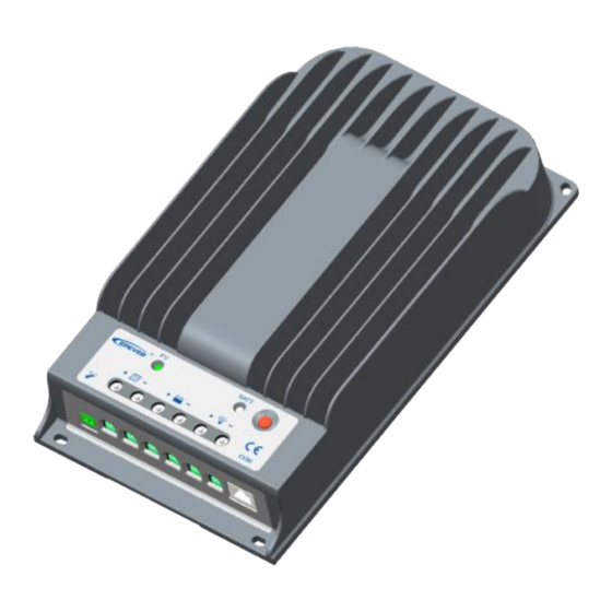
1.2 Characteristics ① ② ⑨ ⑧ ③ ⑦ ④ ⑤ ⑥ Figure 1-1 Tracer BN Series Characteristics Item Name Item Name ① ⑥ Heat Sink Load Terminal RS485 Port ② ⑦ Charging LED indicator (Isolated RJ45 port) ① ③ Port ⑧... -
Page 9: Maximum Power Point Tracking Technology
1.3 Maximum Power Point Tracking Technology Due to the nonlinear characteristics of the solar array, there is a maximum energy output point (Max Power Point) on its curve. Traditional controllers, adopting the switch charging technology and PWM charging technology, can't charge the battery at the maximum power point. - Page 10 that the MPPT mode can improve the usage of solar energy resources. According to our test, the MPPT controller can raise 20%-30% efficiency compared to the PWM controller. (Value may fluctuate due to the ambient circumstance's influence and energy loss.) Figure 1-2 Maximum Power Point Curve The panel may appear Multi-MPP as shading from clouds, trees, or snow in actual application.
-
Page 11: Battery Charging Stage
If the program works improperly after appearing Multi-MPP, the system will not work on the real max. power point. It may waste most solar energy resources and affect the system's normal operation. The typical MPPT algorithm, designed by our company, can track the real MPP quickly and accurately, improve the array's utilization rate and avoid wasting resources. - Page 12 B) Constant Charging When the battery voltage reaches the constant voltage set point, the controller will start to operate in constant charging mode. This process is no longer MPPT charging. In the meantime, the charging current will drop gradually. The process is not the MPPT charging.
- Page 13 increases battery voltage, higher than the standard complement voltage, which gasifies the battery electrolyte. The controller will equalize the battery on the 28th of each month. The constant equalization period is 0~180 minutes. Suppose the equalization isn't accomplished at one-time. In that case, the equalization recharge time will be accumulated until the set time is finished.
- Page 14 Bulk charging stage.
-
Page 15: Installation Instructions
2 Installation Instructions 2.1 General Installation Notes Be very careful when installing the batteries, especially flooded lead-acid batteries. Please wear an eye protector, and have fresh water available to wash and clean any contact with battery acid. Keep the battery away from any metal objects, which may cause a short circuit ... -
Page 16: Pv Array Requirements
2.2 PV Array Requirements Serial connection (string) of PV modules As the core component of the PV system, the controller could be suitable for various types of PV modules and maximize converting solar energy into electrical energy. The series number of PV modules can be calculated according to the open-circuit voltage (Voc) and the maximum power point voltage (Vmpp) of the MPPT controller. -
Page 17: Mounting
refer to the value of I in the PV module specification. When the PV modules are connected in series, the I equals any PV module's I . When the PV modules are connected in parallel, the I equals the sum of the PV module's I . - Page 18 The controller requires at least 150mm of clearance above and below for proper airflow. Ventilation is highly recommended if CAUTION mounted in an enclosure. Figure 2-1 Mounting 1) Connect components to the charge controller in the sequence "① > ② > ③" shown above and ensure that the electrode polarity is connected correctly.
- Page 19 4) The Tracer BN series is a negative ground controller. Any negative solar, load, or battery connection can be earth grounded as required. Unplug the RTS, and the battery's temperature will be 25 ºC. Please connect the inverter to the battery rather than to the controller if the inverter is necessary.
-
Page 20: Operation
3 Operation 3.1 LED Indication Color Indicator Status Indication PV charges the battery Green On Solid with a low current Slowly Green Normal charging Flashing(1Hz) 1. No sunlight Green 2. Connection Error 3. Low PV voltage Green On Solid Normal Slowly Green Full... -
Page 21: Setting Operation
simultaneously 3.2 Setting Operation Figure 3-1 Setting operation Four methods to configure the controller: 1–Remote meter, MT50 2–Super parameter programmer, SPP-02 3–PC monitoring software "Solar Station Monitor"... -
Page 22: Battery Parameters
DO NOT communicate with the PC using the Ethernet cable. Otherwise, the components of the controller will be damaged. For detailed communication cable, refer “Tracer-BN WARNING Accessories” file. The RJ45 interface pin definition is shown below: Pins Define +5VDC +5VDC RS485-B RS485-B... - Page 23 2. Battery voltage parameters Measure the parameters in the condition of 12V/25ºC. Please double the values in the 24V system. Battery type Sealed User Battery parameters Over voltage disconnect 16.0V 16.0V 16.0V 9~17V voltage Charging limit voltage 15.0V 15.0V 15.0V 9~15.5V Over voltage reconnect voltage 15.0V...
- Page 24 2) The following rules must be observed when modifying the parameter's value in the user battery type (the factory default value is the same as the sealed type): Over Voltage Disconnect Voltage > Charging Limit Voltage ≥ Equalize Charging Voltage ≥ Boost Charging Voltage ≥ Float Charging Voltage > Boost Voltage Reconnect Voltage.
- Page 25 Battery LNCM type LNCM LNCM LNCM Battery User User parameters Over voltage 12.8 V 9~17V 25.6 V 29.8 V 18~34V disconnect voltage Charging limit 12.6 V 9~15.5V 25.2 V 29.4 V 18~31V voltage Over voltage 12.5 V 9~15.5V 25.0 V 29.1 V 18~31V reconnect voltage...
-
Page 26: Load Set Mode
(Protection Circuit Modules(BMS))+0.2V; Over Voltage Disconnect Voltage > Over Voltage Reconnect Voltage = Charging Limit Voltage ≥ Equalize Charging Voltage = Boost Charging Voltage ≥ Float Charging Voltage > Boost Voltage Reconnect Voltage; Low Voltage Reconnect Voltage > Low Voltage Disconnect Voltage ≥ Discharging Limit Voltage. - Page 27 24V system: Turn-on voltage (adjustable): 10V, delay 10 minutes. Turn-off voltage (adjustable): 12V, delay 10 minutes. 3. Light ON+ Timer 4. Time Control Control the load on/off time by setting the real-time clock.
-
Page 28: Others
4 Others 4.1 Protection PV Over Current The controller will limit the battery charging current to the Maximum Battery Current rating. Therefore an oversized solar array will not operate at peak power. PV Short Circuit When PV short circuit occurs, the controller will stop charging. Clear it to resume normal operation. - Page 29 Battery Over-discharge When the battery voltage reaches the Low Voltage Disconnect Voltage, the controller stops discharging the battery to protect the battery over-discharged. Battery Overheating The controller detects the battery temperature through the external temperature sensor. If the battery temperature exceeds 65ºC, the controller will automatically start the overheating protection to stop working and recover below 50 ºC.
-
Page 30: Troubleshooting
4.2 Troubleshooting Faults Possible reasons Troubleshooting The charging LED is off during Confirm that the PV and battery PV array the daytime when wire connections are correct and disconnection. sunshine properly tight. falls on the PV. 1. Please check the battery 1. -
Page 31: Maintenance
flashes orange). the input and output circuit. When the temperature is below 75℃, the controller will resume working. Check whether the battery voltage matches the controller's All the LED working voltage. Please change indicators flash System voltage to a suitable battery or reset the (battery indicator error. - Page 32 Confirm that all the system components are ground-connected tightly and correctly. Confirm that all the terminals have no corrosion, insulation damage, high temperature, or burnt/discolored sign. Tighten terminal screws to the suggested torque. Check for dirt, nesting insects, and corrosion. If so, clear up in time. ...
-
Page 33: Technical Specifications
5 Technical Specifications Item Tracer4215BN Electrical Parameters Rated system voltage 12/24VDC Auto Rated charge current Rated discharge current 8V~32V Battery working voltage range 150V(at minimum operating environment Max. PV open circuit voltage temperature) 138V(at 25℃ environment temperature) Battery voltage+2V~108V MPP voltage range Max. - Page 34 Mounting size (L x W) 170mm x 290mm Mounting hole size Φ4.7mm Power cable 4AWG(25mm Weight 2.9kg Please operate the controller at a proper environment temperature. If the actual temperature exceeds the permissible temperature range, the charging and load power will be reduced appropriately;...
-
Page 35: Annex I Conversion Efficiency Curve
Annex I Conversion Efficiency Curve Illumination Intensity: 1000W/m Temp: 25ºC Model: Tracer4215BN 1. Solar Module MPP Voltage(17V, 34V, 68V) / Rated System Voltage(12V) 2. Solar Module MPP Voltage(34V, 68V, 102V) / Rated System Voltage(24V) -
Page 36: Annex Ii Dimensions
Annex II Dimensions Tracer4215BN Dimensions in Millimeters Any changes without prior notice! Version number: V1.0... - Page 37 HUIZHOU EPEVER TECHNOLOGY CO., LTD. Tel: +86-752-3889706 E-mail: info@epever.com support@solarepic.com Website: www.epever.com...
Need help?
Do you have a question about the Tracer 4215BN and is the answer not in the manual?
Questions and answers