Table of Contents
Advertisement
Quick Links
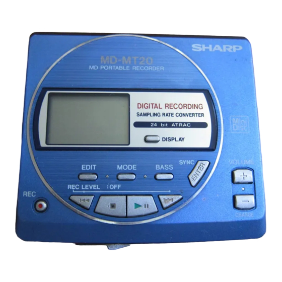
Illustration: MD-MT20H
Illustration: MD-MT16E
SAFETY PRECAUTION FOR SERVICE MANUAL ............................................................................................................... 2
SPECIFICATIONS ................................................................................................................................................................. 3
NAMES OF PARTS ............................................................................................................................................................... 4
OPERATION MANUAL (FOR MD-MT20H) ........................................................................................................................... 5
DISASSEMBLY ...................................................................................................................................................................... 8
REMOVING AND REINSTALLING THE MAIN PARTS ......................................................................................................... 9
ADJUSTMENT ...................................................................................................................................................................... 10
NOTES ON SCHEMATIC DIAGRAM .................................................................................................................................. 23
TYPES OF TRANSISTOR AND DIODE .............................................................................................................................. 23
VOLTAGE ............................................................................................................................................................................ 24
BLOCK DIAGRAM ............................................................................................................................................................... 25
SCHEMATIC DIAGRAM ...................................................................................................................................................... 26
WIRING SIDE OF P.W.BOARD ........................................................................................................................................... 29
WAVEFORMS OF MD CIRCUIT ......................................................................................................................................... 34
TROUBLE SHOOTING ........................................................................................................................................................ 35
FUNCTION TABLE OF IC .................................................................................................................................................... 38
CIRCUIT DESCRIPTION ..................................................................................................................................................... 40
PARTS GUIDE/EXPLODED VIEW
SERVICE MANUAL
CONTENTS
SHARP CORPORATION
- 1 -
MD-MT20H(BL)
MD-MT20H(GL)
MD-MT20H(S)
MD-MT16E(S)
• In the interests of user-safety the set should be restored to its
original condition and only parts identical to those specified be
used.
DIFFERENCE BETWEEN
MD-MT16E AND MD-MT20H
SECTION
Optical Digital cable
None
Remote Control
None
Rechargeable Battery
None
Battery Carrying Case
None
AC Adapter
None
AC Adapter Pad
None
This document has been published to be used
for after sales service only.
The contents are subject to change without notice.
MD-MT20H/16E
No. S5933MDMT20H/
MD-MD16E
MD-MT20H
Used
Used
Used
Used
Used
Used
Page
Advertisement
Table of Contents

Related Manuals for Sharp MD-MT20H(BL)


Summary of Contents for Sharp MD-MT20H(BL)
-
Page 1: Table Of Contents
FUNCTION TABLE OF IC ..............................38 CIRCUIT DESCRIPTION ..............................40 PARTS GUIDE/EXPLODED VIEW PACKING METHOD (MD-MT20H/MT16E FOR U.K. ONLY) This document has been published to be used SHARP CORPORATION for after sales service only. The contents are subject to change without notice. – 1 –... -
Page 2: Safety Precaution For Service Manual
MD-MT20H/16E SAFETY PRECAUTION FOR SERVICE MANUAL Precaution to be taken when replacing and servicing the Laser Pickup. The AEL (Accessible Emission Level) of Laser Power Output for this model is specified to be lower than Class I Requirements. However, the following precautions must be observed during servicing to protect your eyes against exposure to the laser beam. (1) When the cabinet has been removed, the power is turned on without a compact disc, and the Pickup is on a position outer than the lead-in position, the Laser will light for several seconds to detect a disc. -
Page 3: Specifications
MD-MT20H/16E FOR A COMPLETE DESCRIPTION OF THE OPERATION OF THIS UNIT, PLEASE REFER TO THE OPERATION MANUAL. SPECIFICATIONS General DC 2.4V: Rechargeable Nickel-Metal Hydride battery x 1 The continuous recording time is for analogue inputs when the volume level is set to Power source: DC 5V: AC adaptor (AC 230 - 240V, 50/60 Hz) -
Page 4: Names Of Parts
MD-MT20H/16E NAMES OF PARTS Main unit Illustration: MD-MT20H 1. Monaural Long-Play Mode Indicator 1 2 3 4 5 6 2. Record Indicator 3. Level Meter 4. Fast Play Indicator 5. Repeat Indicator 6. TOC Indicator 7. Battery Indicator 8. Random Indicator 9. -
Page 5: Operation Manual (For Md-Mt20H)
MD-MT20H/16E OPERATION MANUAL (FOR MD-MT20H) – 5 –... - Page 6 MD-MT20H/16E – 6 –...
- Page 7 MD-MT20H/16E – 7 –...
-
Page 8: Disassembly
MD-MT20H/16E DISASSEMBLY (B1)x2 Cares before disassembling Key Switch ø1.4x2mm When assembling the machine after disassembling or Top Cabinet repair, observe the following requirements so as to ensure (A1)x2 safety and performance. ø1.4x2mm 1. Remove the batteries from the machine, and take out the (A1)x1 ø1.4x2mm mini-disc. -
Page 9: Removing And Reinstalling The Main Parts
MD-MT20H/16E REMOVING AND REINSTALLING THE MAIN PARTS Remove the mechanism according to the disassembling meth- (A2)x3 ods 1 to 4. (See Page 8.) ø1.4x2.8mm (A1)x1 Spindle Motor Mechanism Flexible How to remove the spindle motor (See Fig. 9-1.) PWB Solder joint 1. -
Page 10: Adjustment
MD-MT20H/16E ADJUSTMENT Test disc MD adjustment needs two types of disc, namely recording disc (low reflection disc) and playback-only disc (high reflection disc). Parts No. Type Test disc High reflection disc MMD-110 (TEAC Test MD) 88GMMD-110 Low reflection disc MMD-212 (TEAC Test MD) 74-minute disc 88GMMD-212 Low reflection disc MMD-213A (TEAC Test MD) 80-minute disc... - Page 11 MD-MT20H/16E Operation in each TEST mode 1. AUTO1 Mode • When the STOP button is pressed while the AUTO1 menu appears or during automatic adjustment, the mode changes to the TEST mode stop state. At this time the adjustment value is not output. •...
- Page 12 MD-MT20H/16E 5. NORMAL Mode • When the STOP button is pressed while the NORMAL menu appears, the mode changes to the TEST mode stop state. • Indication during operation Indication of memory capacity on main unit LCD [ ] + Level meter : Internal mode : Address (Cluster section) : Address (Sector section)
- Page 13 MD-MT20H/16E EEPROM (IC402) writing procedure 1. Procedure to replace EEPROM and write initial value of microcomputer in EEPROM (1) Replace EEPROM. (2) Deprive EEPROM of protection (connect the pins 8 and 6 of IC402). (3) Refer to the latest EEPROM data list. (4) Press the Display button, Ente button and Play button to start the test mode.
- Page 14 MD-MT20H/16E EEPROM DATA LIST (EEPROM version f) Sled setting TEMP setting Item display Set values Item display Set values S L G _ T M _ _ Calculate values S L 2 _ Fucus setting S L M _ Item display Set values S L V _ F G _ _...
- Page 15 MD-MT20H/16E – 15 –...
- Page 16 MD-MT20H/16E – 16 –...
- Page 17 MD-MT20H/16E – 17 –...
- Page 18 MD-MT20H/16E – 18 –...
- Page 19 MD-MT20H/16E – 19 –...
- Page 20 MD-MT20H/16E – 20 –...
- Page 21 MD-MT20H/16E – 21 –...
- Page 22 MD-MT20H/16E – 22 –...
-
Page 23: Notes On Schematic Diagram
MD-MT20H/16E NOTES ON SCHEMATIC DIAGRAM • Resistor: • The indicated voltage in each section is the one measured To differentiate the units of resistors, such symbol as K and by Digital Multimeter between such a section and the chas- M are used: the symbol K means 1000 ohm and the symbol sis with no signal given. -
Page 24: Voltage
MD-MT20H/16E VOLTAGE IC101 IC201 IC401 IC501 IC701 IC801 VOLTAGE PIN VOLTAGE PIN VOLTAGE VOLTAGE VOLTAGE VOLTAGE VOLTAGE VOLTAGE 0.88V 0.72V 2.5V 0.72V 0.2V 2.5V 2.5V 2.32V 2.5V 2.34V 0.72V 1.27V 0.72V 2.35V 0.73V 1.24V 1.25V 2.32V 1.24V 1.25V 0.18V 0.73V 0.71V 1.25V 2.34V... -
Page 25: Block Diagram
MD-MT20H/16E J702 MIC IN J801 (READY FOR J703 J703 Ni - MH Battery PLUG/IN DC IN JACK J701 J701 HEADPHONES REMOTE (4~5.5V) POWER) OPTICAL IN LINE IN LINE CONTROL Dry Battery (2 pieces) 1.7~3.4V IC901 SPINDLE MOTOR DRIVER BA6966FV 1, 3, 4, 5, 6,19,20 M903 M901... -
Page 26: Schematic Diagram
MD-MT20H/16E P27 P28 MAIN PWB-A1 C112 0.033 L203 100mA C209 C111 C110 22P(CH) C107 TP139 C109 IC101 0.0033 0.22 C211 0.012 5P(CH) C106 RF SIGNAL PLAYBACK SIGNAL 0.22 PROCESSOR RECORD SIGNAL ROUT ADAGC R106 IR3R55 EFMAGI ADIPI XL201 TP212 33.868MHz ADIPO TP205 C204... - Page 27 MD-MT20H/16E DADATA TP451 EDIT ADDATA TP452 DISPLY L203 DFCK SKIP DOWN TP453 100mA BCLK TP454 SKIP UP P(CH) LRCK HREC TP455 C211 TP456 P-MODE 5P(CH) ADPON HSTOP TP457 STOP DAPON TP458 VOL DOWN OPTCNT R455 R456 R457 HPLAY TP459 PLAY 5.6K 8.2K R458...
- Page 28 MD-MT20H/16E • NOTES ON SCHEMATIC DIAGRAM can be found on page 23. • The numbers are waveform numbers shown in page 34. TP451 EDIT TP452 DISPLY LCD ASS'Y SKIP DOWN TP453 TP454 SKIP UP TP455 KEY SWITCH TP456 P-MODE FLEXIBLE TP457 STOP TP458...
-
Page 29: Wiring Side Of P.w.board
MD-MT20H/16E MAGNETIC HEAD FLEXIBLE PWB(18) M901 SPINDLE MOTOR OPTICAL PICKUP UNIT(13) MAGNETIC HEAD(24) SW902 DISC MECHANISM PROTECT FLEXIBLE PWB PH901 CN601 PHOTO TO MAIN PWB INTERRUPTER P30 5-H M902 SLED MOTOR CN101 M903 HEAD TO MAIN PWB UP/DOWN MOTOR P30 4-H TO MAIN PWB P30 2-C TO MAIN PWB... - Page 30 MD-MT20H/16E MAIN PWB-A1 (BOTTOM VIEW) R804 R269 TO AUDIO PWB Terminal, Battery IC805 CN702 (235) P32 3-A C258 R255 FLAT CABLE (243) R254 R262 C253 R261 To Key Switch Flexible Ass'y To LCD Ass'y P29 2-E P29 5-E Terminal, Battery (237) Terminal, Battery R252...
- Page 31 MD-MT20H/16E MAIN PWB-A1 (TOP VIEW) R256 SW801 SW801 Ni-MH BATTERY DETECTION R250 IC806 R251 D812 IC803 F871 C805 R268 T0.5A L 63V C876 L821 L822 C600 R600 C874 L600 C821 C651 IC841 C609 L609 C605 C834 R833 C610 C875 C826 C863 IC702 C877...
- Page 32 MD-MT20H/16E TO MAIN PWB AUDIO PWB-A2 (TOP VIEW) CN701 P30 2-B FLAT CABLE (243) CN702 L751 L752 L453 R764 R763 R765 R761 L454 C755 R769 R770 R753 R762 IC703 C491 C758 C756 R716 R754 C712 L703 R714 C757 C759 L704 C760 R757 L719...
- Page 33 MD-MT20H/16E AUDIO PWB-A2 (BOTTOM VIEW) TP066 TP077 TP068 TP062 TP076 TP728 TP064 TP061 TP069 TP086 TP065 TP080 L452 TP093 TP727 TP063 TP082 TP067 TP072 TP092 TP724 TP729 J703 TP070 TP089 REMOTE CONTOL/ TP722 HEADPHONES TP721 TP723 TP071 TP070B TP721B TP725 TP064B TP074 TP726...
-
Page 34: Waveforms Of Md Circuit
MD-MT20H/16E WAVEFORMS OF MD CIRCUIT Stopped 1994 / 12 / 15 22:54:19 Stopped 1994 / 12 / 16 00:24:17 Stopped 1994 / 12 / 16 01:03:40 CH1=1mV CH2=500mV CH3=5V CH4=2V 50ms/div CH1=2V CH2=2V CH3=2V CH4=2V 50us/div CH1=1V CH2=2V CH3=500mV 2ms/div DC 10:1 DC 10:1 DC 10:1... -
Page 35: Trouble Shooting
MD-MT20H/16E TROUBLE SHOOTING It is advisable to use the TEST mode (refer to Error Data Display Mode, P13) indicating the causes of troubles before starting repair. Causes of operation errors (up to 10 errors) are recorded as error codes. This information is useful for repair. - Page 36 MD-MT20H/16E • Abnormal display Is waveform output from CN482 pins 6 to 8? Is waveform output from IC401 pins 9,11,13? Are the pin 4 (VCC) and pin 5 (GND) normal? Check the periphery of IC401. Check between IC401 and CN482. Check for pattern breakage of flexible PWB, check for defects of display microcomputer (replace the display unit).
- Page 37 MD-MT20H/16E • The spindle motor fails to run.Does the head move Check the IC201 periphery. Does the waveform appear on the IC201 pins 24 and 25 after TEST mode AUTO2 completion and in this state? Replace. IC601 Does waveform appear on the IC601 pin 13? Does waveform appear on IC901 pins 1, 19 and 20? L608, IC201, IC901, CN601 and flex, etc.
-
Page 38: Function Table Of Ic
MD-MT20H/16E FUNCTION TABLE OF IC IC401 RH-iX0298AWZZ: System Microcomputer (IX0298AW) (1/3) Port Name Terminal Name Input/Output Function Pin No. P12/TCLKA Input Track cross signal/focus drive detection TCLKB SPIN Input Spindle motor FG pulse detection input CHGON Output Ni-MH battery charge ON output DISCPR Input Disc record inhibition switch input... - Page 39 MD-MT20H/16E IC401 RH-iX0298AWZZ: System Microcomputer (IX0298AW) (2/3) Port Name Terminal Name Input/Output Function Pin No. Input Operation mode selection input 1 INNSW Input Mechanism inner SW position detection input WDTOVF WDTOVF Output Watch dog timer (not used) Input Operation mode selection input 2 _RESET Input Microcomputer hard reset input...
-
Page 40: Circuit Description
MD-MT20H/16E IC401 RH-iX0298AWZZ: System Microcomputer (IX0298AW) (3/3) System LSI expansion output port (6th generation: LR37811) Terminal Name Input/Output Pin No. Port Name Function Remarks EXPORT0 LDCNT1 Output Recording head raising-lowering control output 1 See the separate table *3. EXPORT1 LDCNT2 Output Recording head raising-lowering control output 2 See the separate table *3. - Page 41 MD-MT20H/16E Battery voltage measurement When the battery is being used or while it is being charged, the output of pin 17 should be H (battery voltage measurement output). The output should be held L in the power-off mode and in the other modes. However, when it is necessary to measure the battery voltage, pull pin 17 (battery voltage measurement output) H temporarily, to make the measurement.
- Page 42 MD-MT20H/16E –– MEMO –– – 42 –...
- Page 43 “HOW TO ORDER REPLACEMENT PARTS” To have your order filled promptly and correctly, please furnish the For U.S.A. only following information. Contact your nearest SHARP Parts Distributor to order. 1. MODEL NUMBER 2. REF. No. 3. PART NO. 4. DESCRIPTION For location of SHARP Parts Distributor, Please call Toll-Free;...
- Page 44 MD-MT20H/16E PRICE PRICE PARTS CODE DESCRIPTION PARTS CODE DESCRIPTION RANK RANK INTEGRATED CIRCUITS AC 47 µH,Choke L500 RCILC0344AFZZ AC 2.2 µH,Choke L600 RCILC0331AFZZ AC 4.7 µH,Choke L601~604 RCILC0358AFZZ IC101 VHIIR3R55//-1 AQ RF Signal,Processor,IR3R55 AC 4.7 µH,Choke L608~610 RCILC0358AFZZ IC200 VHI62FP2002-1 AE 2.0V Regulator,62FP2002 L702~704 RCILC0353AFZZ...
- Page 45 MD-MT20H/16E PRICE PRICE PARTS CODE DESCRIPTION PARTS CODE DESCRIPTION RANK RANK C711,712 VCCCCY1HH101J AA 100 pF (CH),50V R253 VRS-CY1JB753D AA 75 kohms,1/16W AD 1 µF,10V C713,714 VCKYTV1AB105K R254 VRS-CY1JB222J AA 2.2 kohms,1/16W AB 0.1 µF,16V C715 VCKYCY1CB104K R255 VRS-CY1JB225J AA 0.2 Mohms,1/16W AE 10 µF,10V,Electrolytic,Tantalum C719 VCSATA1AJ106M...
- Page 46 MD-MT20H/16E PRICE PRICE DESCRIPTION PARTS CODE PARTS CODE DESCRIPTION RANK RANK R802 VRS-CY1JB102J AA 1 kohm,1/16W RCTRH8175AFZZ BM Optical Pickup Unit R803 VRS-CY1JB104J AA 100 kohm,1/16W MSPRP0922AFFJ AD Spring,Drive Grip R804 VHHMSMDC100-1 J AH Thermistor,Positive/Negative C, MSPRP0923AFZZ Spring,Thrust Plate 1.0A NSFTM0292AFFW J AC Shaft,Guide R806...
- Page 47 MD-MT20H/16E PRICE PRICE DESCRIPTION PARTS CODE DESCRIPTION PARTS CODE RANK RANK QTANB9017AWFQ J AD Terminal,Battery,+ OTHER SERVICE PARTS PGIDM0027AW00 Guide,Battery QTANB9016AWFQ J AD Terminal,Battery,+/- UDSKM0001AFZZ AZ Recording Mini Disc LHLDZ1231AW00 AC Holder,Battery Terminal,+/- 88GMMD-110 BV High Reflection Disc MMD-110 MLEVP0094AW00 AC Lever,Battery Push (TEAC Test MD) JKNBZ0624AWSA...
- Page 48 MD-MT20H/16E 501x2 508x2 8-3(PH901) (SW902) 502x3 M901 M903 503x2 M902 Figure 5 MD MECHANISM EXPLODED VIEW – 5 –...
- Page 49 MD-MT20H/16E 229x2 202-1 202-2 603x2 201-1 603x2 PWB-A2 201-2 602x3 PWB-A1 216x2 MD MECHANISM 603x2 603x2 603x2 Figure 6 CABINET EXPLODED VIEW – 6 –...
-
Page 50: Packing Method (Md-Mt20H/Mt16E For U.k. Only)
MD-MT20H/16E PACKING METHOD (MD-MT20H/MT16E FOR U.K. ONLY) Setting position of switches and knobs UNIT HOLD Remote Control HOLD CANCEL 1. Operation Manual [MD-MD20H] TiNSE0255AWZZ 10. Earphones [MD-MT16E] RPHOH0001AWZZ 1. Operation Manual [MD-MT16E] TiNSE0260AWZZ 10. Earphones [MD-MT20H] RPHOH0176AFZZ 2. Service Card TCADS0002AWZZ 11. - Page 51 MD-MT20H/16E –– MEMO –– – 8 –...
- Page 52 MD-MT20H/16E © COPYRIGHT 1999 BY SHARP COPORATION ALL RIGHTS RESERVED. No part of this publication may be reproduced, stored in a retrieval system, or transmitted in any from or by any means, electronic, mechanical, photocopying, recording, or otherwise, without prior written permission of the publisher.