
Related Manuals for ASROCK Rack C236 WS


Summary of Contents for ASROCK Rack C236 WS
- Page 1 C236 WS User Manual Version 1.0 Published January 2017 Copyright©2017 ASRock Rack INC. All rights reserved.
- Page 2 In no event shall ASRock Rack, its directors, officers, employees, or agents be liable for any indirect, special, incidental, or consequential damages (including damages for loss of profits, loss of business, loss of data, interruption of business and the like), even if ASRock Rack has been advised of the possibility of such damages arising from any defect or error in the documentation or product.
- Page 3 Contact Information If you need to contact ASRock Rack or want to know more about ASRock Rack, you’re welcome to visit ASRock Rack’s website at www.ASRockRack.com; or you may contact your dealer for further information. ASRock Rack Incorporation 6F., No.37, Sec. 2, Jhongyang S. Rd., Beitou District, Taipei City 112, Taiwan (R.O.C.)
-
Page 4: Table Of Contents
Contents Chapter 1 Introduction Package Contents Specifications Unique Features Motherboard Layout Onboard LED Indicators I/O Panel Block Diagram Chapter 2 Installation Screw Holes Pre-installation Precautions Installing the CPU Installing the CPU Fan and Heatsink Installation of Memory Modules (DIMM) Expansion Slots (PCI and PCI Express Slots) Jumper Setup Onboard Headers and Connectors Dr. - Page 5 Main Screen Advanced Screen 3.3.1 CPU Configuration 3.3.2 Memory Configuration 3.3.3 Chipset Configuration 3.3.4 Storage Configuration 3.3.5 NVMe Configuration 3.3.6 ACPI Configuration 3.3.7 USB Configuration 3.3.8 WHEA Configuration 3.3.9 Super IO Configuration 3.3.10 Serial Port Console Redirection 3.3.11 H/W Monitor 3.3.12 Voltage Control 3.3.13 Trusted Computing 3.3.14 Instant Flash...
- Page 6 4.2.1 Running The Support CD 4.2.2 Drivers Menu 4.2.3 Utilities Menu 4.2.4 Contact Information Chapter 5 Troubleshooting Troubleshooting Procedures Technical Support Procedures Returning Merchandise for Service Chapter 6 Net Framework Installation Guide Installing .Net Framework 3.5.1 (For Server 2008 R2)
-
Page 7: Chapter 1 Introduction
In case any modifications of this manual occur, the updated version will be available on ASRock Rack website without further notice. You may find the latest memory and CPU support lists on ASRock Rack website as well. ASRock Rack’s Website: www.ASRockRack.com If you require technical support related to this motherboard, please visit our website for specific information about the model you are using. -
Page 8: Specifications
1.2 Specifications C236 WS MB Physical Status Form Factor Dimension 12'' x 9.6'' (30.5 cm x24.4 cm) Processor System Intel® Xeon® E3-1200 v5/v6 Series Processors* *BIOS version 2.0 or above is required for v4 series. Chipset Intel® C236 System Memory... - Page 9 128 Mb AMI UEFI Legal BIOS BIOS Features - Plug and Play (PnP) - ACPI 2.0 Compliance Wake Up Events - SMBIOS 2.8.0 Support - ASRock Rack Instant Flash Hardware Monitor Temperature - CPU Temperature Sensing - MB Temperature Sensing...
- Page 10 Support OS Microsoft® Windows® - Windows 7 (32 / 64 bit) - Windows 8.1 (64 bit) - Windows 10 (64 bit) * Please refer to our website for the latest OS support list. Environment Temperature Operation temperature: 10°C ~ 35°C / Non operation temperature: -40°C ~ 70°C NOTE: Please refer to our website for the latest specifications.
-
Page 11: Unique Features
POST or the <F2> key to enter into the BIOS setup menu to access ASRock Rack Instant Flash. Just launch this tool and save the new BIOS file to your USB flash drive, floppy disk or hard drive, then you can update your BIOS only in a few clicks without preparing an additional floppy diskette or other complicated flash utility. -
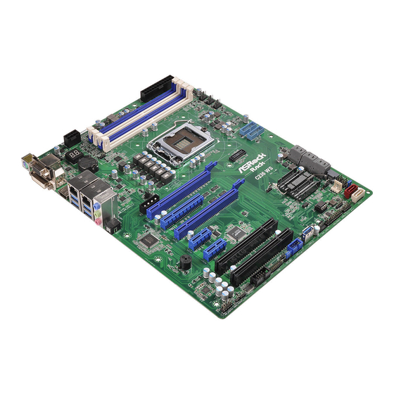
Page 12: Motherboard Layout
CPU_FAN1 USB 3.0 T: USB1 LAN1 FRNT_FAN1 B: USB2 FRNT_FAN2 USB 3.0 T: USB3 LAN2 B: USB4 REAR_FAN1 PCIE_PWR1 USB3_5_6 PCIE7 USB3_7_8 C236 WS PCIE6 PCIE5 Intel PCIE4 BUZZER1 C236 PCIE3 CHASSIS_ID1 CHASSIS_ID2 CLRMOS1 SATA_SGPIO1 PCI2 CHASSIS_ID3 SATA_PWR1 BIOS RoHS... - Page 13 C236 WS Description Rear Fan Connector (REAR_FAN2) ATX 12V Power Connector (ATX12V1) ATX Power Connector (ATXPWR1) 2 x 288-pin DDR4 DIMM Slots (DDR4_A2, DDR4_B2, Blue)* 2 x 288-pin DDR4 DIMM Slots (DDR4_A1, DDR4_B1, White)* CPU Fan Connector (CPU_FAN1) Front Fan Connector (FRNT_FAN1) Front Fan Connector (FRNT_FAN2) USB 3.0 Header (USB3_5_6)
- Page 14 Description Flash Descriptor Security Override Jumper (SEC_OR1) Non Maskable Interrupt Button (NMI_BTN1) TPM Header (TPM1) COM Port Header (COM1) Thermal Sensor Header (TR1) HDMI SPDIF Header (HDMI_SPDIF1) Front Panel Audio Header (HD_AUDIO1) PCIe Power Connector (PCIE_PWR1) Rear Fan Connector (REAR_FAN1) For DIMM installation and configuration instructions, please see p.19 (Installation of Memory Modules (DIMM)) for more details.
-
Page 15: Onboard Led Indicators
C236 WS 1.5 Onboard LED Indicators ATXPWR1 Keyboard /Mouse ATX12V1 REAR_FAN2 DDR3_A1 (64 bit, 240-pin module) Debug DDR3_A2 (64 bit, 240-pin module) DDR3_B1 (64 bit, 240-pin module) CMOS Battery DDR3_B2 (64 bit, 240-pin module) CPU_FAN1 USB 3.0 LAN1 T: USB1... -
Page 16: I/O Panel
1.6 I/O Panel No. Description No. Description PS/2 Mouse/Keyboard Port LAN RJ-45 Port (LAN2)* VGA Port (VGA1) USB 3.0 Ports (USB3_3_4) DVI Port (DVI1) Line In (Light Blue) HDMI Port (HDMI1) Front Speaker (Lime)* LAN RJ-45 Port (LAN1)* Microphone (Pink) USB 3.0 Ports (USB3_1_2) Optical SPDIF Out Port (SPDIF1) LAN Port LED Indications... -
Page 17: Block Diagram
C236 WS 1.7 Block Diagram 128-bit Dual-Channel Memory x 4 Slots PCI-E X16 SLOT7 (x16/x8) DDR4 2133 Channel A PCI-E Gen3 BUS INTEL 100MHz DDR4 2133 Channel B PCIE SWITCH PCI-E X8 SLOT5 (x0/x8) ASM1442 HDMI 1.4 Processor DIGITAL PORT C... -
Page 18: Chapter 2 Installation
Chapter 2 Installation This is an ATX form factor (12'' x 9.6'', 30.5 cm x 24.4 cm) motherboard. Before you install the motherboard, study the configuration of your chassis to ensure that the motherboard fits into it. Make sure to unplug the power cord before installing or removing the motherboard. Failure to do so may cause physical injuries to you and damages to motherboard components. -
Page 19: Installing The Cpu
C236 WS 2.3 Installing the CPU 1. Before you insert the 1151-Pin CPU into the socket, please check if the PnP cap is on the socket, if the CPU surface is unclean, or if there are any bent pins in the socket. Do not force to insert the CPU into the socket if above situation is found. - Page 20 Please save and replace the cover if the processor is removed. The cover must be placed if you wish to return the motherboard for after service.
-
Page 21: Installing The Cpu Fan And Heatsink
C236 WS 2.4 Installing the CPU Fan and Heatsink... -
Page 22: Installation Of Memory Modules (Dimm)
2.5 Installation of Memory Modules (DIMM) This motherboard provides four 288-pin DDR4 (Double Data Rate 4) DIMM slots, and supports Dual Channel Memory Technology. 1. For dual channel configuration, you always need to install identical (the same brand, speed, size and chip-type) DDR4 DIMM pairs. 2. - Page 23 C236 WS The DIMM only fits in one correct orientation. It will cause permanent damage to the motherboard and the DIMM if you force the DIMM into the slot at incorrect orientation.
-
Page 24: Expansion Slots (Pci And Pci Express Slots)
2.6 Expansion Slots (PCI and PCI Express Slots) There are 2 PCI slots and 5 PCI Express slots on this motherboard. PCI slots: The PCI1 and PCI2 slot are used to install expansion cards that have 32-bit PCI interface. PCIE slots: PCIE3 (PCIe 3.0 x1 slot) is used for PCI Express x1 lane width cards. - Page 25 C236 WS Installing an expansion card Step 1. Before installing an expansion card, please make sure that the power supply is switched off or the power cord is unplugged. Please read the documentation of the expansion card and make necessary hardware settings for the card before you start the installation.
-
Page 26: Jumper Setup
2.7 Jumper Setup The illustration shows how jumpers are setup. When the jumper cap is placed on the pins, the jumper is “Short”. If no jumper cap is placed on the pins, the jumper is “Open”. The illustration shows a 3-pin jumper whose pin1 and pin2 are “Short” when a jumper cap is placed on these 2 pins. - Page 27 C236 WS Chassis ID1 Jumper (3-pin CHASSIS_ID1) (see p.6, No. 32) Chassis ID2 Jumper Single motherboard (3-pin CHASSIS_ID2) indication (Default) (see p.6, No. 30) Chassis ID3 Jumper (3-pin CHASSIS_ID3) (see p.6, No. 31)
-
Page 28: Onboard Headers And Connectors
2.8 Onboard Headers and Connectors Onboard headers and connectors are NOT jumpers. Do NOT place jumper caps over these headers and connectors. Placing jumper caps over the headers and connectors will cause permanent damage to the motherboard. System Panel Header C onnec t t he power sw itch, PLED+ PLED-... - Page 29 C236 WS Auxiliary Panel Header This header supports multiple (18-pin AUX PANEL_1) functions on the front panel, (see p.6, No. 26) including the front panel SMB, internet status indicator and chassis intrusion pin. A. Front panel SMBus connecting pin (6-1 pin FPSMB) This header allows you to connect SMBus (System Management Bus) equipment.
- Page 30 Serial ATA3 Connectors These SATA3 connectors (SATA_0) support SATA data cables for (see p.6, No. 11) internal storage devices with (SATA_1) up to 6.0 Gb/s data transfer (see p.6, No. 13) rate. (SATA_2) (see p.6, No. 15) (SATA_3) (see p.6, No. 12) (SATA_4) (see p.6, No.
- Page 31 C236 WS SATA Power Connectors Please connect a SATA (4-pin SATA_PWR1) power cable. (see p.6, No. 20) +12V USB 3.0 Connector (USB3_7) (see p.6, No. 29) IntA_PA_D+ USB 3.0 Headers Besides four default USB 3.0 IntA_PA_D- IntA_PA_SSTX+ (19-pin USB3_5_6) ports on the I/O panel, there IntA_PA_SSTX- (see p.6, No.
- Page 32 3-Pin CPU fan, CPU_FAN_SPEED FA N_SPEED_CONTROL please connect it to Pin 1-3. *For more details, please refer to the Cooler QVL list on the ASRock Rack website. Front and Rear Fan Please connect fan cables to the Connectors...
- Page 33 C236 WS TPM Header This connector supports (17-pin TPM1) Trusted Platform Module (see p.6, No. 36) (TPM) system, which can securely store keys, digital certificates, passwords, and data. A TPM system also helps enhance network security, protects digital identities, and ensures platform integrity.
- Page 34 RRXD1 Serial Port Header This COM header supports a DDTR#1 DDSR#1 (9-pin COM1) serial port module. CCTS#1 (See p.6, No.37) RRI#1 RRTS#1 TTXD1 DDCD#1 HDMI SPDIF Header HDMI SPDIF header, (2-pin HDMI_SPDIF1) providing audio output to (See p.6, No.39) HDMI VGA card, allows the SPDIFOUT system to connect HDMI Digital TV/ projector/LCD...
- Page 35 C236 WS Clear CMOS Pad CLRMOS1 allows you to clear (CLRMOS1) the data in CMOS. To clear (see p.6, No. 28) CMOS, take out the CMOS battery and short the Clear CMOS Pad.
-
Page 36: Dr. Debug
2.9 Dr. Debug Dr. Debug is used to provide code information, which makes troubleshooting even easier. Please see the diagrams below for reading the Dr. Debug codes. Code Description Please check if the CPU is installed correctly and then clear CMOS. Problem related to memory, VGA card or other devices. -
Page 37: Driver Installation Guide
C236 WS 2.10 Driver Installation Guide To install the drivers to your system, please insert the support CD to your optical drive first. Then, the drivers compatible to your system can be auto-detected and listed on the support CD driver page. Please follow the order from top to bottom to install... -
Page 38: Chapter 3 Uefi Setup Utility
Chapter 3 UEFI Setup Utility 3.1 Introduction Th is section explains how to use the UEFI SETUP UTILITY to confi gure your system. Th e UEFI chip on the motherboard stores the UEFI SETUP UTILITY. You may run the UEFI SETUP UTILITY when you start up the computer. -
Page 39: Navigation Keys
C236 WS 3.1.2 Navigation Keys Please check the following table for the function description of each navigation key. Navigation Key(s) Function Description Moves cursor left or right to select Screens Moves cursor up or down to select items + / - To change option for the selected items <Tab>... -
Page 40: Main Screen
3.2 Main Screen Once you enter the UEFI SETUP UTILITY, the Main screen will appear and display the system overview. The Main screen provides system overview information and allows you to set the system time and date. -
Page 41: Advanced Screen
C236 WS 3.3 Advanced Screen In this section, you may set the configurations for the following items: CPU Configuration, Memory Configuration, Chipset Configuration, Storage Configuration, NVMe Configura- tion, ACPI Configuration, USB Configuration, WHEA Configuration, Super IO Configu- ration, Serial Port Console Redirection, H/W Monitor, Voltage Control, Trusted Comput- ing, and Instant Flash. -
Page 42: Cpu Configuration
3.3.1 CPU Configuration Spread Spectrum Use this to enable and disable Spread Spectrum. Intel Hyper Threading Technology Intel Hyper Threading Technology allows multiple threads to run on each core, so that the overall performance on threaded software is improved. Active Processor Cores Select the number of cores to enable in each processor package. - Page 43 C236 WS CPU C6 State Support Enable C6 deep sleep state for lower power consumption. CPU C7 State Support Enable C7 deep sleep state for lower power consumption. Package C State Support Enable CPU, PCIe, Memory, Graphics C State Support for power saving.
- Page 44 Intel TXT(LT) Support Use this to enable or disable Intel Trusted Execution Technology. Long Duration Power Limit Configure Package Power Limit 1 in watts. When the limit is exceeded, the CPU ratio will be lowered after a period of time. A lower limit can protect the CPU and save power, while a higher limit may improve performance.
-
Page 45: Memory Configuration
C236 WS 3.3.2 Memory Configuration DRAM Frequency If [Auto] is selected, the motherboard will detect the memory module(s) inserted and assign the appropriate frequency automatically. ECC Support Use this item to enable or disable DDR ECC Support. -
Page 46: Chipset Configuration
3.3.3 Chipset Configuration Primary Graphics Adapter If PCI Express graphics card is installed on the motherboard, you may use this option to select PCI Express or Onboard as the primary graphics adapter. Top of Lower Usable Dram Maximum Value of TOLUD. Dynamic assignment would adjust TOLUD automatically based on largest MMIO length of installed graphic controller. - Page 47 C236 WS PCIE5 Link Speed This allows you to select PCIE5 Link Speed. The default value is [Auto]. Above 4G Decoding Enable or disable 64bit capable Devices to be decoded in Above 4G Address Space (only if the system supports 64 bit PCI decoding).
- Page 48 Restore on AC/Power Loss This allows you to set the power state after an unexpected AC/power loss. If [Power Off] is selected, the AC/power remains off when the power recovers. If [Power On] is selected, the AC/power resumes and the system starts to boot up when the power recovers. If [Last State] is selected, it will recover to the state before AC/power loss.
-
Page 49: Storage Configuration
C236 WS 3.3.4 Storage Configuration SATA Controller(s) Use this item to enable or disable SATA Controllers. SATA Mode Selection Identify the SATA port is connected to Solid State Drive or Hard Disk Drive. Press <Ctrl+I> to enter RAID ROM during UEFI POST process. -
Page 50: Nvme Configuration
3.3.5 NVMe Configuration The NVMe Configuration displays the NVMe controller and Drive information. -
Page 51: Acpi Configuration
C236 WS 3.3.6 ACPI Configuration Suspend to RAM Select disable for ACPI suspend type S1. It is recommended to select auto for ACPI S3 power saving. ACPI HEPT Table Enable the High Precision Event Timer for better performance. PS/2 Keyboard Power On Use this item to enable or disable PS/2 Keyboard to turn on the system from the power- soft-off mode. - Page 52 USB Keyboard/Remote Power On Allow the system to be waked up by an USB keyboard or remote controller. USB Mouse Power On Allow the system to be waked up by an USB mouse.
-
Page 53: Usb Configuration
C236 WS 3.3.7 USB Configuration Legacy USB Support Use this option to enable or disable legacy support for USB devices. The default value is [Enabled]. PS/2 Simulator Enable PS/2 Simulator. This should be enabled for the complete USB keyboard legacy support for non-USB aware OSes. -
Page 54: Whea Configuration
3.3.8 WHEA Configuration WHEA Support Use this item to enable or disable Windows Hardware Error Architecture. -
Page 55: Super Io Configuration
C236 WS 3.3.9 Super IO Configuration Serial Port Use this item to enable or disable the onboard serial port. Serial Port Address Use this item to select an optimal setting for Super IO device. PS2 Y-Cable Enable the PS2 Y-Cable or set this option to Auto. -
Page 56: Serial Port Console Redirection
3.3.10 Serial Port Console Redirection COM1 Console Redirection Use this option to enable or disable Console Redirection. If this item is set to Enabled, you can select a COM Port to be used for Console Redirection. Console Redirection Settings Use this option to configure Console Redirection Settings, and specify how your computer and the host computer to which you are connected exchange information. - Page 57 C236 WS Bits Per Second Use this item to select the serial port transmission speed. The speed used in the host computer and the client computer must be the same. Long or noisy lines may require lower transmission speed. The options include [9600], [19200], [57600] and [115200].
- Page 58 Legacy Console Redirection Legacy Console Redirection Settings Use this option to configure Legacy Console Redirection Settings, and specify how your computer and the host computer to which you are connected exchange information. Legacy Serial Redirection Port Select a COM port to display redirection of Legacy OS and Legacy OPROM Messages. Serial Port for Out-of-Band Management/Windows Emergency Management Services (EMS) Console Redirection...
-
Page 59: H/W Monitor
C236 WS 3.3.11 H/W Monitor In this section, it allows you to monitor the status of the hardware on your system, includ- ing the parameters of the CPU temperature, motherboard temperature, CPU fan speed, chassis fan speed, and the critical voltage. - Page 60 respective fan speed for each temperature. FRNT_FAN3 Setting Select a fan mode for Fan, or choose Customize to set 5 CPU temperatures and assign a respective fan speed for each temperature. Watch Dog Timer This allows you to enable or disable the Watch Dog Timer. The default value is [Disabled]. Case Open Feature Enable or disable Case Open Feature to detect whether the chassis cover has been removed.
-
Page 61: Voltage Control
C236 WS 3.3.12 Voltage Control DRAM Voltage Configure the voltage for the DRAM. -
Page 62: Trusted Computing
3.3.13 Trusted Computing NOTE: Options vary depending on the version of your connected TPM module. Security Device Support Use this item to enable or disable BIOS support for security device. O.S. will not show Security Device. TCG EFI protocol and INT1A interface will not be available. SHA-1 PCR Bank Use this item to enable or disable SHA-1 PCR Bank. - Page 63 C236 WS Storage Hierarchy Use this item to enable or disable Storage Hierarchy. Endorsement Hierarchy Use this item to enable or disable Endorsement Hierarchy. Device Select Use this item to select the TPM device to be supported. TPM 1.2 will restrict support to TPM 1.2 devices.
-
Page 64: Instant Flash
3.3.14 Instant Flash Instant Flash is a UEFI flash utility embedded in Flash ROM. This convenient UEFI update tool allows you to update system UEFI without entering operating systems ® first like MS-DOS or Windows . Just save the new UEFI file to your USB flash drive, floppy disk or hard drive and launch this tool, then you can update your UEFI only in a few clicks without preparing an additional floppy diskette or other compli- cated flash utility. -
Page 65: Boot Screen
C236 WS 3.4 Boot Screen In this section, it will display the available devices on your system for you to configure the boot settings and the boot priority. Boot Option #1 Use this item to set the system boot order. - Page 66 Bootup Num-Lock If this item is set to [On], it will automatically activate the Numeric Lock function after boot-up. Boot Beep Select whether the Boot Beep should be turned on or off when the system boots up. Please note that a buzzer is needed. Full Screen Logo Use this item to enable or disable OEM Logo.
-
Page 67: Csm Parameters
C236 WS 3.4.1 CSM Parameters Enable to launch the Compatibility Support Module. Please do not disable unless you’re running a WHCK test. If you are using Windows 8.1 64-bit and all of your devices support UEFI, you may also disable CSM for faster boot speed. - Page 68 PCIE6 Slot OpROM This option controls Legacy/UEFI ROMs priority. PCIE5 Slot OpROM This option controls Legacy/UEFI ROMs priority. PCIE4 Slot OpROM This option controls Legacy/UEFI ROMs priority. PCIE3 Slot OpROM This option controls Legacy/UEFI ROMs priority.
-
Page 69: Security
C236 WS 3.5 Security In this section, you may set or change the supervisor/user password for the system. For the user password, you may also clear it. Supervisor Password Set or change the password for the administrator account. Only the administrator has authority to change the settings in the UEFI Setup Utility. -
Page 70: Event Logs
3.6 Event Logs Change Smbios Event Log Settings This allows you to configure the Smbios Event Log Settings. When entering the item, you will see the followings: Smbios Event Log Use this item to enable or disable all features of the SMBIOS Event Logging during system boot. - Page 71 C236 WS View Smbios Event Log Press <Enter> to view the Smbios Event Log records. All values changed here do not take effect until computer is restarted.
-
Page 72: Exit Screen
3.7 Exit Screen Save Changes and Exit When you select this option, the following message “Save configuration changes and exit setup?” will pop-out. Press <F10> key or select [Yes] to save the changes and exit the UEFI SETUP UTILITY. Discard Changes and Exit When you select this option, the following message “Discard changes and exit setup?”... -
Page 73: Chapter 4 Software Support
4.2.4 Contact Information If you need to contact ASRock Rack or want to know more about ASRock Rack, welcome to visit ASRock Rack’s website at http://www.ASRockRack.com; or you may contact your... -
Page 74: Chapter 5 Troubleshooting
Chapter 5 Troubleshooting 5.1 Troubleshooting Procedures Follow the procedures below to troubleshoot your system. Always unplug the power cord before adding, removing or changing any hardware com- ponents. Failure to do so may cause physical injuries to you and damages to motherboard components. - Page 75 1. Verify if the battery on the motherboard provides ~3VDC. Install a new battery if it does not. 2. Confirm whether your power supply provides adaquate and stable power. Other problems... 1. Try searching keywords related to your problem on ASRock Rack’s FAQ page: http://www.asrockrack.com/support...
-
Page 76: Technical Support Procedures
5.2 Technical Support Procedures If you have tried the troubleshooting procedures mentioned above and the problems are still unsolved, please contact ASRock Rack’s technical support with the following information: 1. Your contact information 2. Model name, BIOS version and problem type. -
Page 77: Chapter 6 Net Framework Installation Guide
C236 WS Chapter 6 Net Framework Installation Guide ® To let Intel RSTe works properly, it is required to install Net Framework. Please follow the ® ® steps below to enable “.Net Framework” feature on Microsoft Windows Server 2008 R2. - Page 78 3. Check the box next to .Net Framework 3.5.1 and then click Next. 4. Click Next to continue.
- Page 79 C236 WS 5. Click Install to start installing .Net Framework 3.5.1. 6. After the installation completes, click Close.
Need help?
Do you have a question about the C236 WS and is the answer not in the manual?
Questions and answers