
Summary of Contents for Little Machine Shop HiTorque 3990
- Page 1 HiTorque™ Mini Mill Users Guide Model 3990 • Model 4190 Deluxe • Model 6450 Deluxe, Mirror Display from LittleMachineShop.com ®...
- Page 2 © Copyright 2023 LittleMachineShop.com ® All rights reserved. Written by Chris Wood of LittleMachineShop.com ® Version 1, April 2023 LittleMachineShop.com ® https://www.littlemachineshop.com 396 W. Washington Blvd. #500, Pasadena, CA 91103 (800) 981-9663 Updated 4/21/2023 © 2023 LittleMachineShop.com Page 2 of 54...
-
Page 3: Table Of Contents
Contents Introduction ....................5 Specifications ....................5 Safety Considerations ..................6 General Safety ................... 6 Milling Machine Safety .................. 6 Electrical Safety ..................6 Machine Safety ..................7 Features ..................... 8 Basic Accessories ..................11 Cleaning ....................11 Assembly ....................11 Mounting Your Mill .................. - Page 4 Maintenance ....................28 Cleaning ....................28 Changing Spindle Tools .................. 28 Squaring a Vise ................... 31 Using Parallels .................... 32 Clamping with a Clamping Kit ................32 Finding the Edge of a Workpiece ..............33 Drilling ..................... 34 Milling ..................... 35 Conventional Milling Versus Climb Milling ............
-
Page 5: Introduction
Introduction This user’s guide covers operation and care of the LittleMachineShop.com HiTorque Mini Mill. Be sure to read and understand the safety guidelines presented in this book before using your HiTorque Mini Mill. Specifications End Milling Capacity 0.6" (16 mm) Face Milling Capacity 1.2"... -
Page 6: Safety Considerations
Safety Considerations Always use common sense when using a power tool. Review the following safety instructions. Besides the general safety rules for any power tool, the following include specific considerations for the mini mill. General Safety • Use common sense. Think through the results of your actions before you act. •... -
Page 7: Machine Safety
• In the event of a power outage, turn off all components to ensure that the machine does not restart unexpectedly. Machine Safety • Keep bystanders, children, and visitors a safe distance away while operating any power tool. • Read the manual. Know the operation of every control before you attempt any operation of the machine. -
Page 8: Features
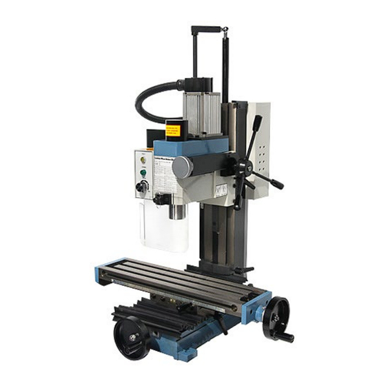
Features Model 3990 Shown 1. Motor 7. Y-axis hand wheel 13. Z-axis travel stop 2. Drawbar (under cap) 8. Air Spring 14. X-axis hand wheel 3. Motor controls 9. Z-axis coarse feed handle 15. X-axis lock lever 4. Spindle 10. Z-axis fine feed knob 16. - Page 9 Model 4190 Shown 1. Motor 8. Saddle 15. Column 2. Drawbar (under cap) 9. Y-axis hand wheel 16. Z-axis travel stop 3. Motor controls 10. Air Spring 17. X-axis DRO Scale & Reader 4. Spindle 11. Z-axis coarse feed handle 18.
- Page 10 Model 6450 Shown 1. Air Spring 8. Saddle Z-axis DRO Scale & Reader 2. Motor 9. Y-axis hand wheel 15. Column 16. Z-axis travel stop 3. Drawbar (under cap) 10. DRO Tablet 11. Z-axis coarse feed 4. Motor controls 17. X-axis hand wheel handle 5.
-
Page 11: Basic Accessories
Basic Accessories The following accessories come with the HiTorque Mini Mill. • Mini Mill Users Guide • 2 T-slot nuts with 3/8"-16 thread • Three open end wrenches (8/10 mm, 14/17 mm, 17/19 mm) • Four hex (Allen) wrenches (3, 4, 5, and 6 •... -
Page 12: Mounting Your Mill
Mounting Your Mill The mini mill must be bolted down to the workbench because it is top-heavy. It is unsafe to operate the mini mill if it is not bolted to a workbench. Before you mount your mini mill, plan the positioning carefully. If you simply bolt it to the middle of the workbench, you won’t be able to turn the Y-axis hand wheel. -
Page 13: Operating Controls
Operating Controls There are several controls used to operate the mill. Become familiar with them before you use the mill. Motor Controls 3990 / 4190 Controls 1. Power and emergency stop (E-stop) switch 2. Speed control Power Switch and Emergency Stop (E-stop) Switch The green power switch enables input power to the speed control circuit board. - Page 14 6450 Controls 1. Power switch & Emergency stop (E-stop) switch 2. Spindle speed readout 3. Speed control knob 4. Z-axis fine feed knob 5. Spindle direction button 6. Start/stop button Power Switch and Emergency Stop (E-stop) Switch The green power switch enables input power to the speed control circuit board. The red E- stop switch disconnects the power.
-
Page 15: Using The Motor Controls
Z-axis fine feed knob See Z-Axis Fine Feed Knob on page 17. Spindle Direction Button The spindle direction button controls the direction the spindle turns. After turning on the power and pressing start, the spindle turns in the forward direction - the direction used for normal turning. -
Page 16: X-Axis Hand Wheel
5. Press the start/stop button to begin the spindle turning. The spindle will begin rotating at the last speed set on the speed dial when the lathe was turned off or the start/stop button was disengaged. The start/stop button will illuminate when engaged. 6. -
Page 17: Y-Axis Lock Lever
Y-Axis Lock Lever The Y-axis lock lever is on the right side of the saddle behind the X-axis hand wheel. Use this lever to lock the Y-axis so it does not move inadvertently. Pulling out on the lever and simultaneously turning it can change the locked position of this lever. -
Page 18: Bluetooth Dro (Models 4190 & 6450)
different position. You might need to adjust the screw in the base of the lever to make this adjustment. Bluetooth DRO (Models 4190 & 6450) The Android tablet included with your DRO has the SIEG DRO app preinstalled. To begin using it, you must pair the tablet to the DRO scales, and you must configure the app, as described in the following sections. -
Page 19: Using The App
° Axis CPI: 5080 • Under W Axis ° Enable W Axis: remove check 5. Tap the Back button at the bottom of the screen when you have made the settings. Using the app Your DRO should now be working. Turn a hand wheel and watch the numbers change. The axis readouts appear at the left top of the screen. -
Page 20: Axis Detail Settings
Axis detail settings Tap one of the axis position values to see the Axis Details. Tap the Position value to enter the current position value. Reduces the position value to half its value. Use this for centering. If you are viewing an absolute value, it stores half the absolute value in the incremental value. -
Page 21: Points And Workspaces
Points and workspaces Points are a set of coordinates that define a spot on your work piece. Workspaces keep track of points that you have recorded. The right side of the display window shows a list of recorded points. You can create points several ways. To save a point: Any time you are at a location you want to save, tap Add Point. -
Page 22: Starting A Work Piece
Choosing a predefined tool To choose a tool and use the predefined offset, simply tap the tool in the list of predefined tools. The Tool Offset window appears. You can adjust any values you need for this job and tap Set Tool Offset. These changes are not saved with the tool. To modify or delete a tool: Tap and hold the tool’s name in the list of predefined tools. - Page 23 5. Raise your edge finder to clear the workpiece and move to the other side of the work piece. 6. Touch off the opposite side of the work piece. 7. Tap the corresponding axis value so Axis Details appears. 8. Tap 1/2. The value changes to half the previous value. Tap Close. Note that the that axis has changed to Incremental.
-
Page 24: Adjustments
Adjustments Keeping your mini mill in adjustment is an ongoing process. You should check all the following adjustments when you set up your mill and then periodically as you use your mill. X-Axis Gib A gib is a strip of metal placed between the bearing surface of two machine parts to ensure a precision fit and provide adjustment for wear. -
Page 25: Y-Axis Gib
Y-Axis Gib The Y-axis gib provides adjustment for the mating dovetails on the base and the saddle that provide the Y-axis (in and out) motion. To adjust the Y-axis gib: 1. Loosen the two lock nuts on the right side of the saddle. 2. - Page 26 To tram the mill: 1. Mount the dial indicator or dial test indicator so that it will rest on the front left and front right corners of the table. 2. Take readings on the left front and right front corners of the table. Calculate the difference to see how much and which way to move the column.
-
Page 27: Lubrication
4. Take additional readings, adding or removing shims. Repeat until the readings are the same to within 0.002". 5. Now mount the dial indicator or dial test indicator so that it will rest on the front center and back center of the table. 6. -
Page 28: Maintenance
The following points on your mini mill require lubrication. Location Lubricant Frequency Notes Column dovetail and Lubriplate 3V Machine Tool Daily rack Table and other Lubriplate 3V Machine Tool Daily Oil lubricates and machined surfaces prevents corrosion Table dovetails Lubriplate 630-AA Lithium- Yearly Based Grease Table feed screws and... - Page 29 To remove a tool from the spindle (Model 3990): 1. Remove the plastic cap from the top of the spindle. 2. Insert the spindle lock pin the hole in the side of the spindle. 3. Use a wrench to loosen the drawbar about ½ turn. 4.
- Page 30 To remove a tool from the spindle (Models 4190 & 6450): The models 4190 & 6450 mini mills come equipped with an electrically interlocked spindle lock. This mechanism makes tool changes easier, faster and safer. When engaged, the plunger automatically drops into the locking hole as the spindle is rotated. An electro- magnetic interlock disables power to the motor, locking the spindle.
-
Page 31: Squaring A Vise
Squaring a Vise When you mount a vise on the mill table, it is important that it be mounted square to the table. If your vise is not square to the table, you will not be able to produce accurate work. The vise is usually mounted with the long axis of the vise perpendicular to the long axis of the table. -
Page 32: Using Parallels
Using Parallels Precision parallels are used to raise the workpiece off the bed of the vise to a position where you can mill the top surface. Parallels come in sets of graduated heights. Choose a pair of parallels that position the top surface of the work above the top of the vise jaws, while keeping enough material between the jaws of the vise for effective clamping. -
Page 33: Finding The Edge Of A Workpiece
When clamping with step blocks and clamp bars, the end of the clamp bar on the step block should be just a little higher than the end on the workpiece. This ensures that the end of the clamp bar makes contact with the workpiece. The stud should be located as close to the workpiece as possible so that the majority of the clamping force is exerted on the workpiece and not the step block. -
Page 34: Drilling
9. Raise the mill’s head so that the edge finder is completely above the workpiece. 10. Set the X-axis dial to zero. 11. Turn the X-axis hand wheel clockwise 0.100". Because your dial has 62.5 divisions, you turn one full turn plus 37 and one half divisions. The movable end of the edge finder is 0.200"... -
Page 35: Milling
Milling You can use collets or end mill holders to hold end mills. The world is split about 50/50 on which is better. We will give you the arguments for both sides and let you decide. Collets End Mill Holders Collets are shorter than end mill holders and End mill holders are longer than collets and so give you more vertical work area. -
Page 36: Conventional Milling Versus Climb Milling
Conventional Milling Versus Climb Milling Climb Milling Conventional Milling Depending on the direction in which you move the workpiece against the end mill you are either climb milling or conventional milling. As shown in the illustration above, you are climb milling when the end mill turns as to climb the slope made by cutting. Climb milling has several advantages and is often recommended for modern milling machines. -
Page 37: Milling Slots
Milling Slots Milling slots is the signature operation for a vertical milling machine. For example, to make a belt-adjustment slot, you plunge mill through the workpiece at one end of the slot, mill the length of the slot and raise the end mill at the other end. But of course, life is not as simple as this. -
Page 38: End Mills
End Mills Conventional wisdom is that 2-flute end mills are used on aluminum, while 4-flute end mills are used on steel and brass. Take a look at why before you make a choice. Two flute end mills Four flute end mills Two-flute end mills are used on aluminum because aluminum is easy to machine and you can take big cuts. -
Page 39: Work Holding
Work Holding There are two main ways to hold work on a mill's table: with a vise or by clamping the workpiece to the table. In our experience, most work can be held in a vise. But from time to time there is a large or odd-shaped workpiece that must be clamped to the table. -
Page 40: Setup Tools
In many cases, you need to lift the workpiece off the table, either because the mill spindle won't reach it or because of a projection on the bottom of the workpiece. 1-2-3 blocks are precision ground to be flat and parallel. Use them as spacers to lift the workpiece. You can also use them as an angle plate by bolting a workpiece to the side of the 1-2-3 block and then clamping the 1-2-3 block to the mill table. -
Page 41: Parts Diagrams
Parts Diagrams Model 3900 Updated 4/21/2023 © 2023 LittleMachineShop.com Page 41 of 54... - Page 42 Model 4190 (1 of 3) Updated 4/21/2023 © 2023 LittleMachineShop.com Page 42 of 54...
- Page 43 Model 4190 (2 of 3) Updated 4/21/2023 © 2023 LittleMachineShop.com Page 43 of 54...
- Page 44 Model 4190 (3 of 3) Updated 4/21/2023 © 2023 LittleMachineShop.com Page 44 of 54...
- Page 45 Model 6450 Updated 4/21/2023 © 2023 LittleMachineShop.com Page 45 of 54...
-
Page 46: Parts List
Parts List Models 3990 Dwg # Description Dwg # Description Base, Solid Column M6 Locking Lever Screw, M8x55 Z-Axis Stop Handle Set, Handwheel Z-Axis Gib Nut, M8 Thin Chamfered M8 Flat Washer Nut, M8 Nylon Locking M8 Lock Washer Handwheel M8x35 Cap Screw Dial Spring M5x6 Set Screw... - Page 47 Dwg # Description Dwg # Description M6x8 Flat Point Set Screw Drawbar Cover M4x16 Pin R8 Drawbar Z-Axis Fine Feed Housing M6x35 Cap Screw Worm Gear 29T Motor Mounting Bracket M4x20 Key Spindle Nut, Left Hand Thread Z-Axis Pinion Timing Belt M3x12 Pin Spindle Timing Pulley Z-Axis Fine Feed Shaft...
- Page 48 Model 4190 Dwg # Description Dwg # Description Base, Solid Column M8 Flat Washer Bolt, Handwheel - Chrome M8 Lock Washer Handle, Handwheel - Chrome M8x35 Hex Head Cap Screw Nut, M8 Nylon Locking Column (Solid) Aluminum Handwheel Z-Axis Rack, 11" Dial Spring M6x12 Flat Head Machine Screw Graduated Dial, 62.5 Divisions...
-
Page 49: M3X14 Pan Head Machine Screw
Dwg # Description Dwg # Description Z-Axis Fine Feed Graduated Dial Chip Guard Thumb Screw R8 to 33JT Drill Chuck Arbor R8 Spindle Pin M6x18 Key Bearing 6007-2RS R8 Spindle Air Spring Lower Mount Drawbar Bushing M6x16 Cap Screw M5x10 Cap Screw M10 Nut Spindle Bearing Cover Air Spring Head Support Shaft... - Page 50 Model 6450 Dwg # Description Dwg # Description R8 to 33JT Drill Chuck Arbor M5x25 Cap Screw R8 Spindle Z-Axis Fine Feed Bracket R8 Spindle Pin Z-Axis Fine Feed Graduated Dial M6x18 Key Dial Spring M5x10 Cap Screw M4x12 Dog Point Set Screw Spindle Bearing Cover Z-Axis Fine Feed Knob Angular Contact Bearing 7007AC...
- Page 51 Dwg # Description Dwg # Description M6x12 Flat Head Machine Screw Fixed plate M3x8 Flat Head Machine Screw M6x8 Machine Screw Z-Axis Scale Bellows Table Retainer M2x4 Rivet Bellows Rear Retainer M8x20 Cap Screw Power Line Washer M8 Power Socket Air Spring Upper Mount M3 Nut M10 Nut...
-
Page 52: Dro Magnetic Scale
Dwg # Description Dwg # Description M3x14 Pan Head Machine Screw M4 Nut Y-Axis DRO Magnetic Scale Bracket DRO Magnetic Scale DRO Magnetic Scale Fine Feed Bracket Screw DRO M4x28 Bracket Studs USB Interface Plug Updated 4/21/2023 © 2023 LittleMachineShop.com Page 52 of 54... -
Page 53: Wiring Diagrams
Wiring Diagrams Models 3990/4190 (SX2LF) Updated 4/21/2023 © 2023 LittleMachineShop.com Page 53 of 54... - Page 54 Model 6450 (SX20) Updated 4/21/2023 © 2023 LittleMachineShop.com Page 54 of 54...
Need help?
Do you have a question about the HiTorque 3990 and is the answer not in the manual?
Questions and answers