Table of Contents
Advertisement
Advertisement
Table of Contents

Related Manuals for MDB Green Climber LV800

Summary of Contents for MDB Green Climber LV800
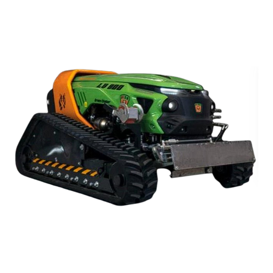
- Page 1 OPERATIONS AND MAINTENANCE MANUAL Green Climber LV800...
- Page 2 GREEN CLIMBER LV800...
- Page 3 MDB machine. The manual includes essential information regarding the care, maintenance, operational safety, and conservation of the machine over time.
-
Page 4: Table Of Contents
TABLE OF CONTENTS 1 - DESCRIPTION OF THE MACHINE Summary of the parts........................Technical data ..........................General information ........................Warranty ............................. Manufacturer’s ID and assistance....................Machine ID ..........................Purpose of the manual, conservation and use................Knowledge of the machine......................List of parts..........................Demolition and disposal of the machine.................. - Page 5 2 - SAFETY Rules for the safe use of the machine..................General information regarding risk analysis ................PPE for machine operations......................Reference standards for machine safety ..................3 – TRANSPORT AND EMERGENCIES Transport of the machine ......................Emergencies ..........................4 – COMMISSIONING AND USE Warnings .............................
- Page 6 Remote control system........................ Remote control LED indicators ....................Indications of the LEDs of the receiving unit................Battery replacement and charging ....................Use of the remote control and management of the vehicle ............Auxiliary controls of the equipment....................Commands on the sides of the remote control................6 - MAINTENANCE AND ASSISTANCE General indications........................
- Page 7 Attachment A: Example of EC declaration of conformity ............Attachment B: Use of shredding equipment................LOG BOOK Routine maintenance........................Special unscheduled maintenance .....................
-
Page 8: Description Of The Machine
1 - DESCRIPTION OF THE MACHINE Brief indication of the parts 1 - Tracks 2 - Oscillation 3 - Structure 4 - Motor hood; 5 - Roll-bar 6 – Cover... -
Page 9: Technical Data
TECHNICAL DATA The following images show the dimensions referring to the fully equipped machine in mm. Height refers to the work quota. - Page 10 Slight changes in measurement are possible during construction DIMENSIONS Machine height 1190 mm Min. machine width 1510 mm Max. machine width 1910 mm Machine length 2510 mm WEIGHTS Empty weight of the machine with all liquids and fuel tank at Kg 1750 Motor only weight Kg 267...
-
Page 11: General Information
(even in part), nor disclosed by any means, used for competitive purposes nor made available to third parties by virtue of the aforementioned rights. MDB S.r.l. therefore prohibits the total or partial reproduction of this manual and the disclosure of its contents in any form. - Page 12 Warranty request: A warranty request must be made in writing to MDB by the dealer, within 4 weeks from the fault, specifying: name and address of the user; type, model, serial number, date of sale, date of the fault, number of hours of operation, circumstances and alleged causes.
-
Page 13: Manufacturer's Id And Assistance
MANUFACTURER’S ID AND ASSISTANCE Name : MDB S.r.l. Head office : C.da Sant’Onofrio, 6/A – LANCIANO (CH) - ITALIA Phone : +39 0872.50221 Fax : +39 0872.50231 E-mail : info@mdbsrl.com VAT number : 01960690699 TECHNICAL ASSISTANCE Technical assistance is always provided by the manufacturer. For further information call: +39 0872.50221... -
Page 14: Purpose Of The Manual, Conservation And Use
- Use the manual so that it is not damaged in any way; - Do not remove, add, change or write in any part of the manual; updates may be carried out only by MDB S.r.l. - Keep the manual in an area protected against damp, so that its life-time is not compromised;... -
Page 15: Knowledge Of The Machine
INFORMATION REGARDING THE MACHINE The following graphic illustration shows the main parts that make up the body of the MDB branded machine called ‘Green Climber LV 800’ with numbers referring to the exploded view of the machine itself: 1. Hood kit 2. -
Page 16: List Of Parts
LIST OF PARTS The Green Climber LV 800 is mainly made up of: 1. S235JR steel base frame. Welded structure; 2. Tracks; 3. Hydraulic oil tank; 4. Diesel tank; 5. Hood; 6. Roll-bar; 7. Rear cover; 8. Air filter; 9. Exhaust assembly; 10. -
Page 17: Signals And Alarms
There is a quick coupling at the front, only to be used for connecting equipment designed and built by MDB. The type of equipment that can be applied to the LV 800, (only if authorized by the manufacturer), is as follows: Shredder;... -
Page 18: Operating Conditions
EN ISO 16231-1: 2013 which specifies the principles for risk assessment with reference to the design and construction of self-propelled machines with operator on board used in agriculture. MDB has tested the machine on sandy terrain up to slopes of 55°; both with the tracks open and with the tracks closed the machine showed excellent stability in all configurations that can be reached. - Page 19 MDB’s technical department, which will perform the necessary checks and reply, confirming the possibility of connection or not. If any equipment not intended by MDB for use with the LV 800 is connected, without first requesting authorisation and receiving a formal reply, MDB is exempted from any constructional or functional liability regarding the machine.
-
Page 20: Sticker Legend
STICKER LEGEND: The following figures and table show the stickers on the machine and relative positions. -
Page 21: Instructions And Danger Stickers
INDICATION AND DANGER STICKERS: The following illustration shows the details of the symbols concerning safety (according to law) and in particular those of danger (yellow) and those regarding indications (blue), the latter relating above all to PPE (personal protective equipment) to be worn during use of the machine. - Page 22 Danger of crushing Danger of expelled Watch your hands objects Danger of crushing and Danger of contact with collision Do not stand moving working parts near the machine On Do not approach the steep terrain, never shredder when the manoeuvre the machine machine is moving.
-
Page 23: Safety
GENERAL INFORMATION REGARDING RISK ANALYSIS The risk analysis concerning the use of the Green Climber LV800 focuses on all the risks typical for machines of this type that operate in the same sector. Those indicated below, which are present during the use of the machine itself, concern the... - Page 24 VIBRATION RISK It should be noted that the Green Climber LV800, compared to machines of the same type that do not have a remote control system, generates vibrations during use. Since it is operated from a distance by means of a remote control, these vibrations cannot harm the operator.
- Page 25 Danger! RISK OF OVERTURNING On steep terrain, never stand or manoeuvre the machine from a position in the area below it, as the machine could overturn in this area. Always stand or manoeuvre the machine from the area above it. In the same way, make sure that no other person authorised to stay on site occupies the aforementioned area.
-
Page 26: Ppe For Machine Operations
Danger! RISKS CONNECTED TO THE AREA OF WORK Before starting work and manoeuvring the machine, make sure that there are no persons and/or animals in the work area. Mark out the work area so that people and/or animals cannot enter. Failure to comply with this safety procedure could cause risk of serious injury and/or death to persons or animals. -
Page 27: Reference Standards For Machine Safety
REFERENCE STANDARDS FOR MACHINE SAFETY TECHNICAL HARMONISED STANDARDS EN ISO 12100:2010 – Safety of Machinery — General Principles for Design — Risk Assessment and Risk Reduction; EN ISO 4254-1:2015 – Agricultural machinery — Safety — Part 1: General Requirements; EN ISO 60204-1:2006 + AC:2010 - Safety of Machinery - Electrical Equipment of Machines - Part 1: General Requirements;... - Page 28 ENVIRONMENTAL ACOUSTIC EMISSION DIRECTIVE OF MACHINES AND EQUIPMENT INTENDED TO OPERATE OUTDOORS 2000/14/CE and 2005/88/CE; ITALIAN LEGAL REGULATIONS LEGISLATIVE DECREE no. 81/2008 and subsequent amendments and additions; LEGISLATIVE DECREE no. 17/2010; LEGISLATIVE DECREE no. 262/2002; LEGISLATIVE DECREE no. 80/2016; LEGISLATIVE DECREE no. 86/2016...
-
Page 29: Transport And Emergencies
3 – TRANSPORT AND EMERGENCIES TRANSPORT OF THE MACHINE The LV 800 machine is delivered to the purchaser adequately protected from impacts during transport and on arrival at its destination, the connection points specially prepared on the machine, positioned in the lateral areas inside the tracks and indicated by the special symbol (see image on the side), must be used to position the machine on the ground. - Page 30 Turn the red emergency button clockwise; The button is now released. To start the engine and continue working, follow the instructions in Chapter 4 of this manual. Remote control failure As indicated previously, the remote control is the only control system of the machine. In the event of a remote control failure, try to repair the machine on site.
- Page 31 Electrical failures: This type of failure is detected when the machine as a whole or only one or more components fail. Excluding damage of the latter, the problem can be caused by the lack of power supply of the same, therefore discharged or damaged battery. In this case the battery should be replaced or recharged.
-
Page 32: Commissioning And Use
4 – COMMISSIONING AND USE WARNINGS Before proceeding with commissioning, read the following indications carefully and carry out the operations following the instructions indicated accurately, in order to minimise the risk of damage and injury to people or objects, as well as to the machine itself. - Page 33 The following table indicates compatible fuels allowed for use by MDB and the engine manufacturer:...
- Page 34 Refuelling engine oil Unscrew the oil refuelling cap “A” (Fig. 4.1) in the upper part or, if this is not accessible, the lateral part “C” and refuel with oil of the prescribed type (Viscosity SAE 5W-40 (≥-25°C); 0W-30 (<-25°C) and with API CJ4 and ACEA E6-E9 specifications.
- Page 35 Loosen screw "C" to let out any air present then screw back in screw "C" (tightening torque at 8 Nm). Screw cap “A” back on. After a few hours of operation, stop the engine, wait for the coolant to return to a temperature close to that of the environment and check the level again.
-
Page 36: Start-Up
Figure 4.7, and switch on the ignition by turning the key (figure 4.8) to position, "1" Fig. 4.7 Please remember that the Green Climber LV800 by MDB is controlled only by the remote control (IMET 880 - See chapter 5 regarding the control system). - Page 37 N.B. Wait for the system to update if the YELLO LED stays on after having pressed the E button. This will take from 3 to 8 minutes, after which the LED will switch off. The thermal engine of the machine (KOHLER Diesel KDI 55 kW) must be started to start up the machine.
-
Page 38: Stop
The diesel engine drives the machine’s hydraulic circuit through hydraulic pumps. The self-propelled Green Climber LV800 machine has been designed for use in the agricultural and forestry sector. There is a quick coupling at the front, only to be used for connecting equipment designed and built by MDB. The equipment authorised by MDB for... -
Page 39: Control System
The control system is made up mainly of two parts: the transmitter (remote control), with which the user transmits the commands to the MDB Green Climber LV800, and the receiver (on the machine itself). The remote control console is practical, clear and user-friendly. It allows to control all functions of the machine, allowing to perform even the most difficult manoeuvres in the most favourable position in complete safety and freedom. - Page 40 Pressing the button indicated in the previous image with the letter "W" will display the following screen, allowing to monitor the angle of the machine both horizontally and vertically. When a horizontal and/or vertical angle of 40° has been reached, the alarm signal superimposed on the machine images will appear (as in the figure at the side Fig.
- Page 41 Alarm descriptions RED HIGH type alarm: 3 beeps are emitted, the error is stored, the message with the red logo remains on the display until manual reset is carried out by the operator. This type of alarm is set for the following anomalies: 1) The engine has reached 110°;...
- Page 42 - Change the air filter 250 hours; - Engine service 500 hours; 4) hydraulic oil pressure below 18 bar; 5) fuel level below 30%; Display indications The indicator shows the level of fuel Diesel reserve in the tank. The display shows the number of Working hours hours that the machine has worked.
-
Page 43: Remote Control System
REMOTE CONTROL SYSTEM As already stated, the MDB Green Climber LV800 has a single control system, that is, by means of the IMET Model 880 remote control, the operation of which will be described in detail in the following paragraphs. -
Page 44: Remote Control Led Indicators
Switching off The machine can be switched off in three different ways using the remote control: Press the STOP button, the remote control will switch off after 10 seconds. Turn the key switch (if present) anti-clockwise. Remove the battery. The transmitter will switch off and the safety circuits opened, all commands will be prevented. The transmitter will, in any case, switch off when the battery is completely discharged. - Page 45 Transmitter TX LED (GREEN) status Indication The transmitter is off or faulty (see relative chapter) The transmitter is working correctly Flashing The transmitter is turned on but is not operational LED status YELLOW ON BLACK BACKGROUND Multi-function indicator Low battery Two flashes every 20s.
-
Page 46: Indications Of The Leds Of The Receiving Unit
INDICATIONS OF THE LEDS ON THE RECEIVER The receiver is equipped with 7 LEDs informing the operator regarding: Operating status Malfunctions Type of failure and diagnostic functions Power supply status Connection status Transmitter Indication “Error B” - Normally off during operation. (Red/green LED) - Red/green for the duration of the data error on channel B. -
Page 47: Battery Replacement And Charging
LED indications during Joystick calibration : Error A and Error B indicators have the same sequence as that of the yellow LEDs on the transmitter during joystick calibration. Joystick Calibration: Error A e Error B LED (COLOUR) test phases: Light on continuously (GREEN) calibration of minimum Single flash followed by a long pause (RED) calibration of maximum:... - Page 48 CB36NIMH, CB3600AC and CB3600DC battery chargers for NiMH cells are equipped with a green LED which indicates the presence of power and a yellow LED which, when inserting the battery, flashes 4 times (pre-charge), then remaining on until charging is complete. The battery charger can detect remaining battery charge and capacity.
-
Page 49: Use Of The Remote Control And Management Of The Vehicle
USE OF THE REMOTE CONTROL AND THE MACHINE Once the engine has been switched on and the transmitter and the receiver are connected (as shown in the previous paragraph) at the pre-set frequency, the machine can start to move using the remote control’s front controls. The basic controls used to drive the machine and use the equipment, as well as other auxiliary controls, are all located in the upper part of the transmitter, including secondary controls relating to the fan and track movement. - Page 50 Joystick 1: this is the main command to decide the direction of movement of the machine, the use of which is intuitive and described by the icons close to it, but which are also described for completeness. There are 8 transmissible commands, which are obtained by moving the Joystick according to the arrows shown next to the following figure.
- Page 51 Moving the Joystick to the top right, the machine will make a right turn in forward gear. Moving the Joystick to the bottom left, the machine will make a left turn in backward gear. Moving the Joystick to the bottom right, the machine will make a right turn in backward gear. Counter-rotation movements Always move the joystick lever to the neutral (central) position before carrying out counter-rotation commands.
- Page 52 Joystick 2: this is the command that decides the movement of the equipment installed at the front of the machine. Also in this case, the use of this command is intuitive and described by the icons close to it, but is also described for completeness. There are 4 transmissible commands, which are reached by moving the Joystick according to the arrows shown next to the figure at the side.
- Page 53 Speed control The speed of movement of the machine is adjusted by means of the knob indicated in Fig. 5.3 and positioned exactly in the centre of the remote control as shown in detail in figure 5.4 below. This command allows to adjust the speed of movement of the machine with the maximum precision according to the needs of the operator.
- Page 54 Description of the commands in the lower part of the remote control: the following figure shows the position of the different sections where the controls are located in the lower part of the remote control as listed below: Section A - Commands regarding the direction of rotation of the equipment; Section B - Commands regarding the change in direction of the commands and that of the track step;...
-
Page 55: Auxiliary Controls Of The Equipment
Section E: in this section there are two controls: a knob that allows to adjust engine rpm, (turning it anticlockwise to lower the rpm to minimum and clockwise to raise it to maximum), as well as a selector for any auxiliary electric commands (AUX 1 or AUX 2). -
Page 56: Maintenance And Assistance
MDB does not assume any liability for damage to the machine or for accidents due to inadequate maintenance, inadequate technical assistance or failure to comply with the laws in force. -
Page 57: Responsibilities And Tasks
Fig. 6.1 Pin for partial opening of the hood Fig. 6.2 Pin for complete opening of the hood Please note! Observe the maintenance and technical assistance instructions and intervals prescribed by MDB. Lack of doing so will void any liability and warranty rights. RESPONSIBILITIES AND TASKS... - Page 58 Observing the indicated maintenance and technical assistance frequency increases the machine’s service life and prevents the onset of unpredictable faults during operations. Failure to observe technical assistance frequency or if it is not carried out by an MDB authorised technical assistance centre, will void warranty rights. General cleaning of the machine List of types of maintenance operations to be carried out on the machine: 1.
- Page 59 4. Control and regulation of mechanical components; 5. Replacements. Service maintenance symbols: Functional test Replacement Visual inspection Restoring the Level of Liquids Cleaning At the end of each working day Inspection Action Cooling fluid Control panel display and remote control LEDs Engine oil Hydraulic oil Regulator and engine speed lever...
- Page 60 Fuel level Engine All safety devices Fuel filter/water separator Every 50 hours of operation or at least once every 6 months Inspection Action Radiator fins Every 250 hours of operation or at least once every 6 months Inspection Action Air filter Cleaning the machine Only clean the device when it is not connected to the power supply, every day or at least after each use.
-
Page 61: Maintenance Of The Engine
Wet or damp electrical components can cause the device to malfunction or create short circuits in the electronic systems. Instructions for high pressure cleaning Caution! Failure to follow these instruction could damage the device. The water/detergent temperature must not exceed 60°. The nozzle must always be kept at a sufficient distance from the machine. - Page 62 Screw back on the upper oil filler cap “A” and/or side cap "C” (See figures 5.1 and 5.2). Replacement: every 500 hours of operation Please note! MDB recommends using 10 W 40 oil. Caution! If the oil level is too low or the oil pressure warning light comes on, the cause must be identified and solved.
- Page 63 Make sure that the cap on the radiator or expansion tank, if any, is properly fitted before starting up the vehicle, to prevent liquid or steam from escaping at high temperatures. (See figures 5.3, 5.4, 5.5 and 5.6) Control and cleaning the air filter –...
- Page 64 Oil or water side cleaning After having removed the exchanger, clean by circulating nitro thinner oil inside the radiator, taking care to circulate the solvent from the bottom up. Clean the inside of water radiators with abundant water. This operation can take from 10 to 30 minutes according to the requirements encountered during the inspection of the exchanger.
- Page 65 MDB machines must normally operate. Do not stay in the area behind the machine (recommended area for normal use of the machine), and make sure that other workers are not in the area when using the machine, to avoid being hit by any debris ejected by the radiator.
- Page 68 Daily visual checks: The checks and associated maintenance or replacement measures referred to in this paragraph must be carried out daily and, in any case, before each use. Please note! Missing, damaged or worn components must be replaced immediately. The following list regards the daily checks to be carried out on the different parts of the machine before each use : Clamping elements: Check the safety systems, the working condition of the screws, deformation of the bolts and the necessary safety conditions.
- Page 69 If the machine does not stop when the emergency button is pressed, there is a high risk of fatal accidents. Working with a defective emergency stop switch is gross negligence. Do not use the machine if the emergency button(s) does not work, contacting the MDB support centre immediately. Check command operation: Press any control lever on the remote control or on the control panel.
- Page 70 Important! MDB recommends using biodegradable lubricants. Do not mix different lubricants together. Even biodegradable greases must not be released into the environment. Lubricants must be free from solid residues. Do not use graphite based lubricants. Caution! Failure to respect maintenance schedules, improper or lack of lubrication can damage the device and lead to high repair costs and downtime.
-
Page 71: Maintenance Of The Tracks
Caution! If lubricant gets into your eyes, rinse immediately with clean water and contact a doctor or go to the hospital! If you get lubricant on your skin, clean the affected area with abundant clean water. Checking and refuelling the hydraulic oil level The hydraulic oil level must be refuelled and checked with the machine not on a slope and with the engine stopped. - Page 72 Maintenance of the hydraulic system must be carried out at least once a year by MDB’s authorised service centre and, in any case, taking into account the hours of use of the machine.
-
Page 73: Technical Assistance
TECHNICAL ASSISTANCE Important! Technical assistance can only be carried out by MDB authorised assistance centres. Otherwise, any form of warranty is void. See the machine’s operating time on the control unit display to programme technical assistance. When the counter shows a use of 0 to 10 hours, the machine owner must start to plan the machine's maintenance. - Page 74 Technical assistance symbols Functional test Replacement Visual inspection Check the tightening of screws Cleaning First technical assistance after 10 hours of operation or in any case after 6 months. Maintenance Action Engine oil level Coolant liquid level and radiator control Dry air filter cartridge Rubber pipes Check the tightening of screws and nuts...
- Page 75 Every 50 hours of operation or at least once a year. Maintenance Action Fuel filter/water separator: empty Battery check Check and clean the radiator fins Every 125 hours of operation or at least once a year. Maintenance Action Tracks: wear, link condition, pinions, lower rollers Tighten the track screws Alternator belt Reversible radiator fan compressor filter...
- Page 76 Every 500 hours of operation or at least once a year. Maintenance Action Engine oil Engine oil filter cartridge Fuel filter cartridge Track Alternator Hydraulic oil Hydraulic oil filter cartridge Remote control All safety devices Pump capacity - rpm Electrical lines/hydraulic pipes, tightening of screw clamps Control levers, control bars Rubber sleeves (air/coolant intake) Fuel pipes...
- Page 77 Every 1000 hours of operation Maintenance Action Fuel tank Rubber sleeves (air/coolant intake) Hydraulic piping Hydraulic oil filter cartridge Coolant liquid Coolant sleeves Every 1500 hours of operation Maintenance Action Fuel pipes Track Alternator (in the case of hard work) Every 2000 hours of operation or in any case every 2 years Maintenance Action...
- Page 78 Every 5000 hours of operation Maintenance Action Starter motor Alternator Track Alternator (in the case of normal working) Track tread height ≤ 10 mm Maintenance Action Tracks...
-
Page 79: Relay And Fuse Positioning
RELAY AND FUSE POSITIONING: R1 R3 Positioning of Boxes “A” and “B” Box “A”: relay and auxiliary function fuses Legend of Box “A” fuses and relays: F1 – Display R1 – Lights (OPT); R2 – Extraction (OPT) F2 – Horn F3 –... -
Page 80: Quick Troubleshooting Guide
F1 – Display R4 R5 F2 – Horn R4 – Main; R5 – Starter F3 – Clearance lights F8 – Main F4 – Battery charger F8 R6 F5 – Cleaner F6 – Lights R6 – A.C. Pump Box “B”: control unit fuses and relays Legend of Box "B”... - Page 81 PROBLEM SOLVING GUIDE ENGINE PROBLEM CAUSE SOLUTION Emergency button pressed Disengage emergency button Battery contact key not Insert/connect battery contact key inserted/connected 1. Machine does not start Out of fuel Fill the tank Fuse blown Replace damaged fuse Brakes locked / hydraulic oil cold Move backward and forward repeatedly until unlocked 2.
- Page 82 REMOTE CONTROL PROBLEM CAUSE SOLUTION Flat battery Recharge the battery Remote control connection not Connect carried out transmitter and receiver 6. Radio remote control not working Emergency button pressed Disengage emergency button Transmitter with serial number Use a transmitter with the same serial different from that of the receiver number as the receiver Lack of radio signal...
-
Page 83: List Of Authorised Workshops
BEEPER / HORN PROBLEM CAUSE SOLUTION Fuel running out Fill the tank Alternator problem Contact the dealer 13. Intermittent signal while moving Carry out maintenance as indicated Routine maintenance expired by the operations and maintenance manual Low oil level Do not use the machine until the 14. - Page 84 MDB AUTHORISED WORKSHOPS Italy: MDB S.r.l. C.da S. Onofrio 6/A 66034 Lanciano Tel. +39 0872 50221 E-mail: vendite@mdbsrl.com Australia: S.M.E PTY LTD mstead@smemowers.com.au Belgium: MAAIERS VERSCHUEREN BVBA info@maaiers-verschueren.be Chile: ROBOTIKA LIMITADA jcatalan@robotika.cl - pgonzalez@robotika.cl South Korea: HAN'A SS CO. LTD kimwinnie@gmail.com...
- Page 85 France: FSI-FRANSKAN SAS anthony@fsi-franskan.com BRICO' TECH S.A.R.L. commercial@bricotech-esd.fr;garreljm@orange.fr Germany: VOGT GmbH Werksvertretungen & Co. KG w.vogt@vogtgmbh.com m.wortmann@vogtgmbh.com Japan: GIGA Solar Co., Ltd yano@gigasolar.co.jp Ireland: MURPHY BROS (FERNS) LTD. sales@murphybrosferns.com Iceland: DATEK ICELAND Datek@datek.is Norway: Maskin Importören AS post@maskinimp.no...
- Page 86 New Zealand: OMC POWER EQUIPMENT msw@omc.net.nz;sales@omc.net.nz The Netherlands (Holland): FEEDCENTRE BV j.vandertol@machines4green.nl Poland: LIFTON POLSKA SP.J. handlowy@liftonpolska.pl;dariamisiak@hotmail.com Portugal: GREENPLACE LDA jrgaivoto@gmail.com; greenplacelda@gmail.com KILWORTH MACHINERY LTD mark@kilworthmachinery.co.uk Czech Republic: ALFA PROFI s.r.o. soukal@alfaprofi.cz Romania: PROGEMA FOREST SRL-D info@utilajepentrupadure.ro...
- Page 87 Russia: DOKART PROFI LTD vib@dokartspb.ru Slovakia: COMENERG, a.s. urminsky.p@gmail.com comenerg.as@gmail.com Spain: I.L.A.G.A. SL gustavo@ilaga.es United States: Green Climber of NORTH AMERICA marty@greenclimberna.com zoe@greenclimberna.com Sweden: KENNETH ANDERSSON ostrahult@tele2.se Switzerland: BUILTEC dguccione@builtec.ch Hungary: AGROLÁNC KFT kralla@agrolanc.hu...
- Page 88 ATTACHMENT A - GREEN CLIMBER LV 800 --- EXAMPLE OF CE CONFORMITY DECLARATION...
- Page 89 Green Climber LV 800. MDB declines any liability if equipment other than that listed in this manual, or in any case not authorised by MDB, is applied to the LV 800. The Green Climber LV 800 can be delivered to the purchaser with the SHREDDER already installed. In this case, use the machine’s lifting points, located in the areas identified in the photos, to place it on the ground, as described...
- Page 90 Figure A Figure B Align the machine with the equipment by lifting the latter from the supports and fixing the equipment to the plate using the appropriate locking stops by inserting them in the holes in the lower central part between the shredder and the plate. The shredder must now be connected to the hydraulic system in order to power up and operate the equipment itself.
- Page 91 against the plate shown in Figure C, connecting to the system located on the right side of the machine as shown in figure E. The connection to the plate also takes place this time by pressure, but to ensure its fixing and complete the operation it is necessary, after completing the three couplings on the plate, secure the connection by lifting the lever at the side of the plate itself and precisely by turning it anticlockwise until the red button on the opposite side of the lever, and located on the left side of the connection block to the hydraulic system shown in figures C and D, clicks.
- Page 92 Figure E Figure F Shredder commands: Once the two different connections described in the previous pages have been carried out, the shredder will respond correctly to the commands given by the operator via the remote control as described on pages 47 and 48 of this operations and maintenance manual (of which Attachment B forms an integral part).
- Page 93 LOG BOOK Routine maintenance NAME OF THE MACHINE Green Climber LV 800 SERIAL NUMBER YEAR OF MANUFACTURE Date Maintenance after 10 hours of operation Person in charge Stamp and signature...
- Page 101 Date Maintenance after 50 hours of operation Person in charge Stamp and signature...
- Page 106 Date Maintenance after 125 hours of operation Person in charge Stamp and signature...
- Page 109 Date Maintenance after 250 hours of operation Person in charge Stamp and signature...
- Page 112 Date Maintenance after 500 hours of operation Person in charge Stamp and signature...
- Page 113 Date Maintenance after 1000 hours of Person in charge Stamp and signature operation...
- Page 114 Date Maintenance after 2000 hours of Person in charge Stamp and signature operation...
- Page 115 Date Maintenance after 2500 hours of Person in charge Stamp and signature operation...
- Page 116 Special unscheduled maintenance Date Reason for the maintenance Person in charge Stamp and signature...
- Page 117 Date Reason for the maintenance Person in charge Stamp and signature...
- Page 118 C.da Sant’Onofrio, 6/A 66034 Lanciano (CH) – ITALY Tel. (+39) 0872.50221 – Fax (+39) 0872.50231 E-mail: info@mdbsrl.com – Web: www.mdbsrl.com...
Need help?
Do you have a question about the Green Climber LV800 and is the answer not in the manual?
Questions and answers