
Related Manuals for Dometic SEASTAR POWER ASSIST PA1200-2HP


Summary of Contents for Dometic SEASTAR POWER ASSIST PA1200-2HP
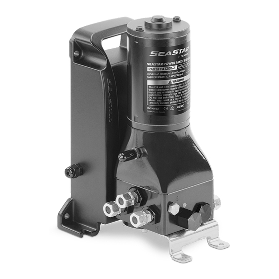
- Page 1 SEASTAR POWER ASSIST (P/A) Hydraulic Power Assist for SeaStar Steering Systems Installation and User’s Manual — Book 17.2 [REVISION P] Form No. 298403 | ©2022 Dometic...
- Page 2 ©2021 Dometic All Rights Reserved. This document, subject matter and all information herein is the sole, exclusive and confidential property of Dometic and shall not be disclosed, copied, reproduced or used in whole or in part for any purpose other than as specifically authorized in writing by Dometic.
-
Page 3: Table Of Contents
Table of Contents Specifications .................iv 1 Important Safety Information ..........1-1 1.1 Explanation of symbols ............ 1-1 1.2 Safe operation ............... 1-2 1.3 Safety considerations for installers ........1-3 1.4 Safety labels ..............1-4 2 System Operation ..............2-1 2.1 Pre-trip inspection ............2-3 2.2 Maintenance inspection .......... -
Page 4: Specifications
7 Mounting Templates ............7-1 7.0.1 Floor mounting ............7-1 7.0.2 Wall mounting ............7-3 8 Warranty ................8-1 8.1 2 -Year limited warranty ........... 8-1 8.2 Return goods procedure ..........8-2 8.3 Technical support ............8-2 8.4 Authorised service centers & distributors ......8-2 Specifications Models Operating voltage... -
Page 5: Important Safety Information
If you have any questions about safe installation or operation of this system, contact Dometic Marine. Please don’t guess. 1.1 Explanation of symbols The symbols below are used throughout this publication to alert you to potential hazards involved with the operation and installation of this product. -
Page 6: Safe Operation
• Know and obey all applicable federal, state, and municipal laws and regulations that govern boating in your area. Dometic recommends all boat operators take a boating safety course. • Never operate a boat while under the influence of drugs or alcohol. -
Page 7: Safety Considerations For Installers
– refer also to those instructions. • Do not substitute any component of the system without written authorization from Dometic. Dometic parts are rigorously engineered and tested to ensure system integrity. Substitution of components may compromise safety, performance, and reliability. -
Page 8: Safety Labels
1.4 Safety labels Figure 1-1. Safety labels. WARNING! If a decal is missing or becomes illegible, it must be replaced. Contact Dometic technical support for a replacement copy. -
Page 9: System Operation
2 System Operation How it works The Dometic SeaStar Power Assist (P/A) is an electronically controlled gear pump that is added into the hydraulic steering circuit between the helm and steering cylinder. Fluid circulated by the helm pump enters the power assist and is routed through the gear pump to the steering cylinder(s). - Page 10 Some installers or builders will wire the P/A to turn on with an accessory switch, or they may wire the accessory switch in series with the engine ignition signal. In this case you will need to turn the P/A on with a switch. This feature allows you to turn the power assist off and steer manually in the event batteries are very low.
-
Page 11: Pre-Trip Inspection
2.1 Pre-trip inspection Perform the following inspection prior to every use: 1. Check the steering fluid level in the helm. See section 4.3.2. 2. Verify immediate steering response when turning steering wheel(s). Turn the steering wheel slowly to port and to starboard through the full range of motion and make sure the engines or rudders respond immediately. - Page 12 Notes...
-
Page 13: Installation
• Check that you have all the components and tools you need. If you need technical assistance, or wish to report an error in our documentation, please contact Dometic technical support. Email: seastar@dometic.com Phone: 604.248.3858... -
Page 14: Compatibility
Compatibility 3.1.1 The SeaStar P/A and P/A PRO are designed for use in recreational marine applications. See the matrix below for helm, cylinder, P/A, and hose compatibility. NOTE The power assist can be used with helms of any displacement, but we recommend 1.4, 1.7, and 2.0 helm pumps for optimal performance. -
Page 15: Installation Overview
Installation overview 3.1.3 STEP 1 – Install system components Install the SeaStar helm(s) and steering cylinder(s) according to the installation instructions provided with the components. Install the compensating line fitting to the helm as shown in section 3.2. Install the SeaStar power assist pump as shown in section 3.3. Review the system plumbing requirements in section 3.4, then find your configuration in sections 3.5 to 3.7 and make the required hose connections. - Page 16 ORB fittings: Remove the plug from the bottom-most R port. Thread the 45° fitting (supplied with the P/A) into the helm port until the fitting washer (item 2) contacts the face of the helm port. Tighten hand tight. Do not use a wrench. Re-position the fitting to the desired orientation by turning it counterclockwise to a maximum of one full turn.
-
Page 17: Pump Installation
3.3 Pump installation The SeaStar P/A can be wall-mounted to a bulkhead or transom, or floor- mounted with the accessory mounting foot (included). Mounting templates for wall and floor mounting are provided in section 7. When determining where to mount the pump, consider the following: •... -
Page 18: Installing 90° Fittings
Installing 90° fittings 3.3.1 The minimum bend radius for SeaStar and SeaStar PRO hose is 3.5” (9 cm). If you are installing the pump with the hose exit close to a bulkhead or other obstruction that won’t allow a suitable bend radius, you can replace the straight fittings at the pump output (labeled C1 and C2) with 90°... -
Page 19: Plumbing The System - General Requirements
3.4 Plumbing the system – general requirements WARNING! Do not cut the hose or attempt to install reusable fittings. Failure of the hose or fittings may lead to loss of steering control resulting in a collision and/or ejection from the boat leading to property damage, personal injury, and/or death. -
Page 20: Seastar Outboard Front Mount Cylinders And I/O Cylinder
3.5 SeaStar outboard front mount cylinders and I/O cylinder Outboard front mount cylinder part #’s: HC5345-3, HC5347-3, HC5348-3, HC5358-3, HC5375-3, HC5445-3, HC6345-3, HC6358-3, HC6845(S), HC6850 NOTE Includes older models without -3 suffix. I/O cylinder part #: HC5332 3.5.1 Single cylinder diagram PORT STARBOARD Helm pump model... -
Page 21: Dual Cylinder Installations
3.5.2 Dual cylinder installations PORT STARBOARD CONFIG. A CONFIG. B ALIGNMENT VALVE Helm pump Wheel Turns model and Config. A Config. B displacement ‘Parallel‘ ‘Series’ 1.7 cu.in. per revolution 2.0 cu.in. per revolution 2.4 cu.in. per revolution Table 3-4. Figure 3-5. -
Page 22: Triple Cylinder Installations
3.5.3 Triple cylinder installations PORT STARBOARD CONFIG. C CONFIG. D ALIGNMENT VALVE Helm pump Wheel Turns model and Config. C Config. D displacement ‘Parallel‘ ‘Series’ 1.7 cu.in. per 14.5 revolution 2.0 cu.in. per 12.5 revolution 2.4 cu.in. per 10.3 revolution Table 3-5. -
Page 23: Seastar Outboard Side Mount And Splashwell Mount Cylinders
3.6 SeaStar outboard side mount and splashwell mount cylinders Side mount cylinder part #’s: Splashwell cylinder part #’s: HC5370 and HC5370-3 HC5380 and HC5380-3 NOTE When using an unbalanced cylinder, the number of wheel turns will be different port to starboard. NOTICE! Do not use SeaStar PRO systems with HC5370 side mount and/or HC5380 Splashwell mount cylinders as SeaStar PRO systems are not... -
Page 24: Seastar Inboard And Sterndrive Cylinders
3.7 SeaStar inboard and sterndrive cylinders All inboard and sterndrive cylinder part #’s Except: HC5332 Connect hoses as follows: Helm Cylinder Starboard side Port side Table 3-8. PORT STARBOARD Helm pump Wheel Turns model and HC5312-3 HC5313-3 displacement 1.7 cu.in. per revolution 2.0 cu.in. -
Page 25: Autopilot Connection Detail
3.8 Autopilot connection detail NOTE Installation and operation can be simplified with the purchase of a SeaStar Autopilot pump and adapter kit HA1205. Contact Dometic to ensure this will work with your autopilot controller. When adding an autopilot to the system: Connect the A/P pump output to the steering lines between the power assist pump and the steering cylinder(s) as shown in figure 3-9. -
Page 26: Electrical Installation
7” (ISO: 200 mm) of the power source. Use a fuse or circuit breaker rated for marine use, with a rating of 50A (25A in 24V installations). Dometic offers two ABYC-compliant fuse options that you can find listed with the available accessories in section 6. - Page 27 NOTE The power harness may be cut to length if required. Dometic recommends sealed, heat-shrink crimp terminals. Install according to manufacturer’s recommendations. NOTE In multi-engine applications Dometic recommends the use of a Dual Ignition Control Kit (HA1201), which will ensure the P/A is on when any engine is running.
- Page 28 Notes 3-16...
-
Page 29: Filling And Purging The System
4 Filling and Purging the System NOTICE! Do not turn on the power assist until you have filled the steering system and purged it with the P/A off. Running the power assist pump dry may cause irreparable damage. NOTE If the system is plumbed with a liquid alignment valve as shown in Config B (figure 3-5) and Config D (figure 3-6), refer to the instructions that came with the valve for additional bleeding instructions. -
Page 30: Manual Fill And Purge
4.2 Manual fill and purge You will need two people to thoroughly fill and purge the system. One person may not be able to remove all the air from the system, resulting in spongy and unresponsive steering. NOTE Ensure fluid is always visible in the helm fill tube when purging. If the fluid level disappears into the pump air may be drawn into the system, which will increase filling time. - Page 31 STEP 1 — Remove air from compensating line Install the fill tube fitting into the helm’s fill port and attach a bottle of steering fluid. NOTE Filling the helm reservoir with a funnel before you connect the fill tube will reduce the time it takes to purge. On the P/A, open the manual bleed valve two full turns (see figure 4-2) and the reservoir bleed fitting one to two turns.
- Page 32 STEP 2 — Purge the steering lines and cylinder Turn the steering wheel clockwise until the cylinder rod is fully extended as shown. Open the indicated bleed fitting. Connect the purge tube to the bleed fitting and direct it into a clean container.
- Page 33 Continue turning the steering wheel counterclockwise until the cylinder rod is fully extended in the other direction. Open the bleed fitting and direct the purge tube into a container. TURN COUNTER- TURN COUNTER- TURN COUNTER- CLOCKWISE CLOCKWISE CLOCKWISE OPEN OPEN STARBOARD STARBOARD SIDE...
- Page 34 Twin station, single cylinder system configuration Procedure: Perform steps 1–3 at station number 1. Move the helm fill tube to station number 2 and repeat steps 2 and 3 from there. Repeat for any additional stations. STATION NO.2 STATION NO.1 P/A UNIT CYLINDER Figure 4-15.
-
Page 35: System Checks
STATION NO.2 STATION NO.1 P/A UNIT CYLINDER NO.2 CYLINDER NO.1 Figure 4-17. 4.3 System checks At this point the system must be checked for fluid level, possible leaks, air removal, and possible interference. Perform all the checks in this section and correct any deficiencies before considering the installation to be complete. -
Page 36: System Pressure Test
VERTICAL 1/2" (12.5 mm) 20° Figure 4-18. 4.3.3 System pressure test Turn the helm to hard over, then force the helm another quarter to half turn past the stop point. ✓ This will pressurize one side of the system to the helm relief pressure. The helm relief will make noise when the relief valve operates —... -
Page 37: Troubleshooting Guide
NOTICE! Dometic does not recommend disassembly of a Power Assist, a helm pump or removing a steering cylinder rod/shaft at any time. Doing so may cause more damage, leading to irreparable damage and costly replacements. - Page 38 SOLUTION FAULT CAUSE 6. Steering is very See fault #1 P/A unit is not turned on. hard (stiff) Partially kinked or collapsed line. Check all lines for a sign of a collapsed or kinked line H1, H2 or R port screen filters are Remove H1, H2 and R hose and fittings.
-
Page 39: Warning Lights
Green and red lights indicate the status of the SeaStar Power Assist. • Green. Steady (no flash) Normal operation. • Red. Steady (no flash) Internal fuse blown. Solution: Contact Dometic. • Red. Two flashes, long pause Standby mode, lack of calibration. Solution: Contact Dometic. • Red. Three flashes, long pause Calibration mode. - Page 40 Notes...
-
Page 41: Accessories
6 Accessories 6.1 Fitting kits HF5530 HF5540 HF6005 HF6006 Tee Fitting 45° Fitting Tee Fitting Tee Fitting (3 per kit) (2 per kit) (3 per kit) (2 per kit) 3/8" TUBE 3/8" 3/8" 3/8" TUBE 1/4" NPT TUBE TUBE 3/8" TUBE 3/8"... -
Page 42: Power Harness Fuse Kits
6.3 Power harness fuse kits HA1206: Inline maxi fuse kit, 50A. HA1207: Battery mount fuse kit, 50A. 6.4 SeaStar Power Purge JR part# HA5445-2 SeaStar/BayStar Power Purge Jr. is the quickest way to bleed a SeaStar/ BayStar system in the field and assure a rock-solid steering feel every time! Figure 6-3. -
Page 43: Mounting Templates
7 Mounting Templates 7.0.1 Floor mounting 5" (127 mm) NOTICE! If this template has been printed or photocopied, verify the dimensions with a ruler before drilling. TOP OF POWER ASSIST UNIT 1-3/8" 2-1/2" 2 x .22" (35 mm) (64 mm) - Page 44 This page left intentionally blank.
-
Page 45: Wall Mounting
7.0.2 Wall mounting 3.7" 4 x .22" (94 mm) NOTICE! If this template has been printed or photocopied, verify the dimensions with a ruler before drilling. FRONT OF POWER ASSIST UNIT 5.0" (127 mm) - Page 46 This page left intentionally blank.
-
Page 47: Warranty
8 Warranty 8.1 2-Year limited warranty The SeaStar Solutions warrants its products to be free from defects in ® materials and workmanship for a period of two years from the date of original retail purchase, provided, however, the warranty period for SeaStar Solutions products used commercially or in any rental or other ®... -
Page 48: Return Goods Procedure
8.2 Return goods procedure Contact our warranty department at Marine.Warranty@dometic.com for instructions. 8.3 Technical support Phone: 604.248.3858 email: seastar@dometic.com Hours: Monday to Friday 05:00 – 15:30 PST 8.4 Authorized service centers and distributors For a current listing of all our authorized service centers and distributors... - Page 49 Notes...
- Page 50 Notes...
- Page 52 Mobile living made easy. DOMETIC VANCOUVER 3831 NO.6 ROAD RICHMOND, B.C. CANADA V6V 1P6 www.dometic.com © 2022 DOMETIC PRINTED IN CANADA 11/22 ISO 10592 Please scan FORM NO. 298403 REV. P this QR code and watch our latest Boating Safety video.
Need help?
Do you have a question about the SEASTAR POWER ASSIST PA1200-2HP and is the answer not in the manual?
Questions and answers