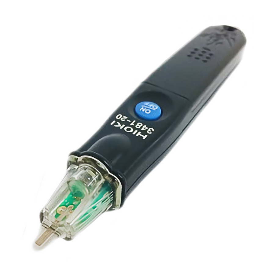
Hioki 3481-20 - Voltage Detector Manual
- Instruction manual (2 pages) ,
- Instruction manual (4 pages)
Advertisement
Introduction
Thank you for purchasing the HIOKI "Model 3481-20 VOLTAGE DETECTOR." To obtain maximum performance from the instrument, please read this manual first, and keep it handy for future reference.
Overview
This non-contact type of voltage detector unit enables the hot-line state of AC voltage to be checked through the wire or cable covering
Initial Inspection
When you receive the instrument, inspect it carefully to ensure that no damage occurred during shipping. If damage is evident, or if it fails to operate according to the specifications, contact your dealer or Hioki representative.
Maintenance and Service
- To clean the instrument, wipe it gently with a soft cloth moistened with water or mild detergent. Never use solvents such as benzene, alcohol, acetone, ether, ketones, thinners or gasoline, as they can deform and discolor the case.
- If the instrument seems to be malfunctioning, confirm that the batteries are not discharged, before contacting your dealer or Hioki representative.
Safety
This manual contains information and warnings essential for safe operation of the instrument and for maintaining it in safe operating condition. Before using it, be sure to carefully read the following safety precautions.
 This instrument is designed to comply with IEC 61010 Safety Standards, and has been thoroughly tested for safety prior to shipment. However, mishandling during use could result in injury or death, as well as damage to the instrument. Be certain that you understand the instructions and precautions in the manual before use. We disclaim any responsibility for accidents or injuries not resulting directly from instrument defects. |
Safety Symbol
 | In the manual, the symbol indicates particularly important information that the user should read before using the instrument. The symbol printed on the instrument indicates that the user should refer to a corresponding topic in the manual (marked with the symbol) before using the relevant function. |
 | Indicates a double-insulated device. |
 | Indicates AC (Alternating Current). |
 | Indicates DC (Direct Current). |
The following symbols in this manual indicate the relative importance of cautions and warnings.
|
|

Symbols for Various Standards
 | Indicates the Waste Electrical and Electronic Equipment Directive (WEEE Directive) in EU member states. |
 | Indicates that the product conforms to regulations set out by the EC Directive. |
Measurement categories
This instrument complies with CAT IV (600 V) safety requirements. To ensure safe operation of measurement instruments, IEC 61010 establishes safety standards for various electrical environments, categorized as CAT II to CAT IV, and called measurement categories. These are defined as follows.
CAT II: Primary electrical circuits in equipment connected to an AC electrical outlet by a power cord (portable tools, household appliances, etc.)
CAT III:Primary electrical circuits of heavy equipment (fixed installations) connected directly to the distribution panel, and feeders from the distribution panel to outlets.
CAT IV: The circuit from the service drop to the service entrance, and to the power meter and primary overcurrent protection device (distribution panel).
Using a measurement instrument in an environment designated with a higher-numbered category than that for which the instrument is rated could result in a severe accident, and must be carefully avoided. Use of a measurement instrument that is not CAT-rated in CAT II to CAT IV measurement applications could result in a severe accident, and must be carefully avoided.

Usage Notes
Follow these precautions to ensure safe operation and to obtain the full benefits of the various functions.

This instrument is measured on a live line. To avoid electric shock when measuring live lines, wear appropriate protective gear, such as insulated rubber gloves, boots and a safety helmet.

- This instrument is designed for use indoors. It can be operated at temperatures between 0°C and 40°C without degrading safety.
- This instrument is not designed to be entirely water- or dust-proof. Do not use it in an especially dusty environment, nor where it might be splashed with liquid. This may cause damage.
- To avoid damage to the instrument, protect it from physical shock when transporting and handling. Be especially careful to avoid physical shock from dropping.
- Do not look directly into the penlight nor shine the light at another person's eye. Doing so may cause damage to the eye.
Measuring Principal
The static-induction voltage detection method using static coupling lets you verify the hot-line state of a wire.
| Operating voltage range | 40 V to 600 V AC (When placed into contact with a 2 mm2 insulated wire equivalent to 600 V polyvinyl chloride insulated wires) Maximum sensitivity adjustable range: 4 V to 80 V The operating voltage indicates a line-to-earth voltage of the grounded circuit. |
| Operating frequency range | 50 Hz/ 60 Hz |

* Although a detected current will flow to the ground through your body, the current, which is less than 1 μA, will not adversely affect you.

Examples of inapplicable circuits
| Inapplicable circuit | Example | Cause |
| Grounded wire |
| Voltage is less than operating voltage range. |
| Shielded wire | shielded wire | Shield layer prevents signal from being detected. |
| Non-grounded power system |
| Line-to-earth voltage is unstable. |
| DC power system |
| Static coupling point cannot flow DC. |

Even if you place the instrument into contact with an inapplicable circuit, the instrument may detect AC voltage of adjacent cables/wires, being activated.
Check a voltage using a voltmeter when in doubt.
Detection
Performance Check and Voltage Detection
The maximum rated voltage between input terminals and ground is 600 V AC. Attempting to measure voltages exceeding 600 V with respect to ground could damage the instrument and result in personal injury.

- The white LED indicates battery consumption but is not a guarantee of the performance of the instrument. Be sure to check its performance using a known power source (e.g., AC outlet) prior to use.
- The instrument voltage detector works using a live AC circuit. It will not work using an earthed wire or neutral point. If there are several lines, such as 2-phase wires and 3-phase wires, perform voltage detection on each line separately.
- The instrument cannot perform voltage detection on a shielded wire. (See the below figure.)

- Be sure to grip the instrument firmly during measurement. But, do not touch the portion beyond the barrier. It will not produce any detection.
- Make sure the detecting element properly contacts the object to be measured. (See the below figure.)


Performance Check
 Be sure to check the following before and after use to avoid electrical shock.

| VOLTAGE DETECTOR | Object to be Measured |
| The white LED still lighting up, and the red LED flashes and the buzzer sounds. | Live. |
| Only the white LED lights up. | Not live or below the Operating-voltage range. |
Adjusting sensitivity

- Slide the battery cover to the position where the sensitivity adjustment trimmer appears.
- Turn the trimmer with a precision screwdriver to adjust the sensitivity, placing the detecting element into contact with an object to be detected.
Clockwise: Increase the sensitivity to detect a relatively low voltage.
Counterclockwise: Decrease the sensitivity to detect a relatively high voltage

The sensitivity will vary according to wire types or operating environments. Please adjust the sensitivity appropriately depending on your operating environment.
Replacing the batteries
- Do not mix old and new batteries, or different types of batteries. Also, be careful to observe battery polarity during installation. Otherwise, poor performance or damage from battery leakage could result.
- Battery may explode if mistreated. Do not short-circuit, recharge, disassemble or dispose of in fire.
- Handle and dispose of batteries in accordance with local regulations.
- Keep batteries away from children to prevent accidental swallowing.
- Use LR44 button alkaline battery.
- After use, always turn OFF the power to prevent battery drain.
Replacing the batteries
- Turn the switch off.
![]()
- Unlock the battery cover by pressing in the opening with the tip of a pen, screwdriver or other thin apparatus and slide the cover towards the end of the voltage detector.
![]()
- Replace the old batteries with new ones. Confirm correct polarity when installing the new batteries.
![]()
- Slide the battery cover back into locked position.
![]()


Name of Parts

Specifications
Basic Specifications
| Function | Detection | |
| Operating Voltage Range | 40V to 600 V AC (When brought into contact with a 2-mm 2 lated cable equivalent to 600 V polyvinyl chloride insulated wire ) Maximum sensitivity variable range 40 V to 80 V AC | |
| Operating frequency | 50 Hz/60 Hz | |
| Pilot light | The red LED flashes and the buzzer sounds when the wire is live. | |
| Additional Functions | Light Battery check (The white LED is dim or out when the batteries are low.) | |
| Power supply | Three LR44 button alkaline batteries. | |
| Dimensions | Approx. 20W× 126H × 15D mm (0.79"W × 4.96"H × 0.59"D)(excluding projections) | |
| Mass | Approx. 30 g (1.1 oz.) (including three LR44 button alkaline batteries) | |
| Operating environment | Indoors, altitude up to 2000 m (6562 ft.) | |
| Operating temperature and humidity | 0°C to 40°C (32°F to 104°F), 80% RH or less. (no condensation) | |
| Storage temperature and humidity | -20°C to 60°C (-4°F to 140°F), 80% RH or less. (no condensation) | |
| Product warranty period | 3 years | |
| Accessories | Instruction manual Three LR44 button alkaline batteries (Installed in the instrument, for operation check) | |
| Standards | Safety | EN61010, Pollution degree2, Measurement category IV 600 V (anticipated transient overvoltage 8000 V) |
| EMC | EN61326 | |
Electrical Specifications
| Maximum rated voltage to earth | 600 V AC |
| Dielectric strength | 8.54 kV rms(between the detecting element and main body) |
| Rated supply voltage | 1.5 V DC × 3 |
| Operating supply-voltage range | From 4.95 V to the voltage at which the white LED goes out (central value: 3.6 V) |
| Maximum rated power | 550 mVA (Max.) |
| Continuous operating time | Approx.5 hours (Power ON Standby state) |
| Auto power off | The power will be turned off automatically if the instrument remains idle for 3 minutes after the power is turned on. To reset, turn the power on again using the Power ON switch. |
If a malfunction is suspected
Although the following phenomena, which are unavoidable in the detection principle, can be observed, the instrument has no malfunction.
| Phenomenon | Cause |
| Even after the sensitivity adjustment or at a distance of tens of millimeters from circuits, the instrument detects the live circuits with a voltage of 200 V AC or higher. | Model 3481-20 is intended mainly to detect circuits with a voltage of 100 V AC. The sensitivity variable range is specified as from 40 V to 80 V AC in consideration of safety. Thus, the instrument may detect circuits with a voltage of 200 V AC or higher even after the sensitivity adjustment or at a distance from the circuit. |
| The instrument incorrectly detects metalware including steel desks as live. | Metalware close to AC power may charge AC potential (induced potential) to ground due to the influence of electrostatic capacitance, resulting in incorrectly detecting. |
| If the instrument is rapidly moved closer to or away from non-live circuits or DC circuits, the instrument detects live state temporarily. | The non-live circuits or DC circuits may charge static electricity, temporarily resulting in incorrectly detecting. |

Documents / ResourcesDownload manual
Here you can download full pdf version of manual, it may contain additional safety instructions, warranty information, FCC rules, etc.
Advertisement

Need help?
Do you have a question about the 3481-20 and is the answer not in the manual?
Questions and answers