Krups Espresseria Automatic XP7200, XP7220, XP7240 Servicing Manual
- Installation manual (14 pages) ,
- Servicing manual (20 pages)
Advertisement
- 1 RANGE
- 2 COMPONENTS
- 3 OPERATION
- 4 PERFORMANCES
- 5 TOOLING AND EQUIPMENT REQUIRED FOR DISASSEMBLY & RE-ASSEMBLY
- 6 DISASSEMBLY
- 7 RE-ASSEMBLY
- 8 SERVICING AFTER CLOGGING-UP OF GROUND COFFEE
- 9 CLEANING AND SCALE REMOVAL CYCLES
- 10 PRE-LISTED FAULTS
- 11 TROUBLESHOOTING DIAGNOSIS & CORRECTIVE ACTIONS
- 12 AFTER-SALES (A-S) MODE OPERATION
- 13 POST-SERVICING COMPLIANCY TEST
- 14 GRAPHIC DISPLAY TEST
- 15 Documents / Resources
RANGE
| Pictographic model: XP7200 | black facing silver panel | Claris Filter (France) |
| Graphic model: XP7220 | black facing silver panel | Claris Filter |
| Graphic model: XP7240 | titanium facing stainless steel panel | Claris Filter +Auto-cappuccino |
COMPONENTS
The appliance is made up of:
- 1 1.3-L removable water tank
- 1 flowmeter to proportion the volume of water
- 1 15-bar pump + 16-bar relief valve
- 1 motorized hydraulic distributor
- 1 1300-W thermoblock system with:
- 1 coffee water circuit and 1 steam circuit
- 1 integrated percolation chamber
- 1 NTC for electronic temperature regulation and two 216°C thermal fuses
- 1 system for discharging the ground coffee by means of an ejection ram and scraper
- 1 hydraulic plunger for closing the percolation head
- 1 grinder
- 2 electronic boards for:
- thermoblock temperature regulation
- mesuring the waterflow volume by counting flowmeter pulses.
- 1-cup, 2-cup, hot water (graphic model), steam, cleaning and scale removal cycle operations
- current function display via indicator light (pictographic models)
- after service information (number of cycles per function, failure code....)
OPERATION
NTC electronic temperature regulation:
Coffee: 108°C (position 1), 111°C (position 2), 113.5°C (position 3)
Steam: 140°C in preheating, 132°C in steam production
Safety cut-off: 190°C
1-cup cycle:
See cycle description with hydraulic diagram.
2-cup cycle:
2-cycles of 2-half-cups sequencing.
Cleaning cycle: only applied to the coffee circuit.
Succession of cycles pumping 50ml of water / 2-minute pauses. Scale removal cycle: applied to coffee and steam circuit.
Succession of cycles pumping 50ml of water / 1-minute pauses.
Automatic priming function:
Priming is automatic if there is no flow during actuator down phase Æ pumping via steam nozzle.
PERFORMANCES
Coffee temperature (50cc):
- First coffee: 75°C
- Subsequent coffees: 77°C
Coffee temperature adjustment: +/- 2°C in position 1 or 3
Steam (125cc of water at 15°C, 1 min): 77 +/- 5°C
Hot water (125cc): 85 +/- 5°C
TOOLING AND EQUIPMENT REQUIRED FOR DISASSEMBLY & RE-ASSEMBLY
- Tamper Torx TX - 10H magnetized screwdriver (cover)
- Small Pozidriv No.1 screwdriver (control electronics protective cover)
- Gripping pliers (high-pressure tube clamps).
- Vacuum cleaner with small nozzle for ground coffee (clogging)
- Small, flat-tip screwdriver (high-pressure hose clamps)
- No.2 male hexagonal "Allen" key (coffee filter)
- Antistatic wriststrap for work on electronic boards
DISASSEMBLY
| Parts to be disassembled | ||||||
| Facing panel | Cover | Body | Technical mount | Facing mount | Facing | |
| Grinder | ● | ● | ● | |||
| Tamping head | ● | ● | ||||
| Control board | ● | ● if necessary replace board | ● | |||
| Power board | ● | ● | ● | |||
| Pump | ● | ● | ● | |||
| Flowmeter | ● | ● | ● | |||
| Thermoblock / actuator | ● | ● | ● | ● | ||
| Fuses | ● | ● | ● | ● | ||
| Distributor | ● | ● | ● | ● | (●) | |
| Steam nozzle | ● | ● | ||||
| Coffee nozzle | ● | ● | ||||
Body: (provides visual access to most parts inside the coffee-maker)
Remove the facing panel (raise and disengage the 6 hooks).
Remove the coffee bean container.
Remove the cover (2 screws under the cup-rest lid + 1 screw under the coffee bean container + 2 clips at the rear removable by pulling on the rear cover rib.
(Do not remove the cup-rest lid or the or the cleaning tablet spout)
Remove the bottom 2 screws on the facing + 2 rear screws in the base.
Slide the body towards the rear: this can only be done when the 2 rear screws have been completely removed; vertically push back the cover which protects the electronic circuit.
Grinder
No particular instructions: see re-assembly.
Ring kept in place on the grinder bush by 4 clips.
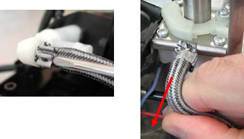
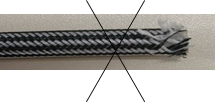
High-pressure hoses:
Unclip the clamp using a small flat-tip screwdriver (without removing it from the hose).
Disconnect the hose and bend it to prevent the braid slipping onto the silicone tube (do not pull straight):
Pump + Relief valve
No particular instructions (to be confirmed with the new dampers).
Tamping head
Can be disassembled without removing the technical mount: be careful not to offset the tamping head mount when unscrewing.
 access to the coffee outlet grid, the creamy seal and the tamping head seal.
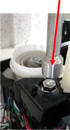
Switch control plate on the actuator
Unclip the 2 clips (access from the top). Compress the actuator by pressing on the top nut (using a socket spanner or equivalent).
Disassemble the switch control plate.
Flowmeter
No particular instructions.
Power electronic board
Electronic circuit mount maintained in the shroud by means of 2 clips at the lower part.
Control electronic board
Use an antistatic wriststrap
Remove the facing (2 screws + 4 clips accessible via side holes).
On the graphic model, it is possible to replace the display device (take particular care when disconnecting the bundle on the elctronic board).
Fuse
To access, remove the facing panel (2 screws in the lower part + 2 screws in the technical mount).
Raise the technical mount so as to disconnect the 2 bushings in the facing panel.
Determine why the fuses blew before replacing.
Check that there are no blow traces on the base and the tamping head.
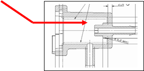
Coffee nozzle
Unclip the coffee pipe.
Remove the nozzle clip by means of a rule or a screwdriver placed between the clip and the facing mount:

Technical mount: (provides access to the distributor and thermoblock/actuator sub-assembly)
Unclip and remove the coffee inlet pipe and disconnect the hose on the tamping head.
Remove the window.
Remove the mounting screws from the technical mount.
Disconnect the connectors and the electronic circuit wires and take the wires out of the grommets.
Remove the technical mount with the grinder in place (the wires connected to the actuator switches pass through the shroud opening).
Thermoblock / NTC / soldered lugs sub-assembly
There is no provision for dismantling this sub-assembly.
The only parts which may be replaced are:
- Tamping head parts (creamy seal, O-ring, coffee grid...)
- The ejection scraper
- The actuator switch control plate with its spring and 3 switches
- The interface and its seal
- The ejector rod "Barista" seal
Remove the 3 thermoblock/actuator sub-assembly mounting screws in the base.
Disconnect the distributor/thermoblock coffee hose from the distributor
Disconnect the thermoblock/distributor steam hose from the thermoblock system (if necessary remove the drain from the distributor after disconnecting the coffee drain hose from the distributor).
Disconnect the steam nozzle hose.
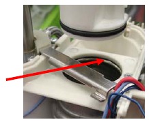
Thermoblock system and ejection scraper Interface
Remove the ejection scraper (this may be a little difficult as the screwdriver is not in line with the screw).
Distributor
Remove the 2 distributor mounting screws in the base (Phillips-head indentation). Disconnect the distributor/thermoblock steam hose from the thermoblock (remove the drain from the distributor, if necessary after disconnecting the coffee drain hose from the distributor). Remove the 3 thermoblock/actuator sub-assembly mounting screws in the base and tilt the unit so as to have access to the hoses connected to the distributor.
Access to the distributor may be facilitated by removing the facing panel (2 screws + 4 clips) and the facing mount (2 screws in the lower part).
Ejection rod "Barista" seal
Remove the tamping head
Unscrew the thermoblock/actuator from the bottom of the coffee-maker and lift it up
Raise the ejector and remove the plunger head.
Remove the "Barista" seal.
Steam nozzle
Remove the panel and the facing (2 screws + 4 clips).
The nozzle is fixed in the facing mount by 3 clips (inaccessible from the front) and is unclipped by pulling on the nozzle.
Lead
No specific instructions.
Removable tank
The valve gasket is difficult to replace.
RE-ASSEMBLY
Re-assembly is carried out in reverse order to disassembly.
Hoses
It is possible to re-use a hose after disassembly provided disassembly precautions were respected: any damaged hose or one with a frayed braid must be replaced.
Use Norma Cobra 7.5 clamps.
Lock the clamps with gripping pliers and check that they have been properly assembled:

Grinder
Indexing and mounting of the grinder ring on the coffee-maker are to be carried out with:

- the grinder set with bushing red marker facing the indexing ball
- the driving pin located at stop on "fine grinding" position
Ensure that wires go through the grommets.
NB: check that the brass spacers are mounted in the grinder screwing holes.
Check the ground coffee cake thickness after any work carried out on the grinder or electronics.
It is possible to adjust grinding time electronically to obtain specified cake thickness: 11 to 13 mm for 60-ml strong espresso.
Pictographic model
- Consult the grinding time programmed in the coffee-maker:
see grinder setting 0, 2, 4, 6 or 8 in the small display in line 22 of the 1st-level AfterSales (A-S) mode.
GRINDER 1 (applied until 13/02/2006)
- Access to V16 setting mode (self-test procedure at the end of the assembly line)
- With cake tray, draw and tank removed
- Press "steam" key + mains connection
![]() "cake tray" light comes on + "water" light flashes
"cake tray" light comes on + "water" light flashes
- Replace the cake tray, draw and tank
- Set volume selector on minimum position
- Place a receptacle under the coffee nozzle
- Press standard coffee key start of standard coffee cycle
- Blue On/Off light comes on
- With the rotating button, select the light corresponding to the one indicated in the table below.
- Press the "service" key to validate (3 relay pulses)
- Disconnect the coffee-maker.
- Access to V17 setting mode and future versions (self-test procedure at the end of the assembly line):
![]() same as for V16 except that setting operation is carried out before the standard coffee cycle
same as for V16 except that setting operation is carried out before the standard coffee cycle - With cake tray, draw and tank removed
- Press "steam" key + mains connection
![]() Blue On/Off light comes on (or another lamp if the selector is not on the minimum position)
Blue On/Off light comes on (or another lamp if the selector is not on the minimum position)- With the rotating button, select the desired cake thickness in accordance with the table below.
- Press the "service" key to validate
![]() "Cake tray" light comes on + "water" light flashes
"Cake tray" light comes on + "water" light flashes- Disconnect the coffee-maker.
| Light comes on on the pictographic model | On/Off | Cake tray | Tank | Clean | Calc |
| Grinder position (read-off in line 22 of A-S mode) | 0 | 2 | 4 | 6 | 8 |
| Time for strong coffee grinding (secs.) (grinder 1 13/02/2006) | 4.1 | 4.3 | 4.5 | 4.7 | 4.9 |
GRINDER 2 (applied from the 14/02/2006)
Access to V28 setting mode and future versions (self-test procedure at the end of the assembly line):
setting procedure the same as V17, but with data of table below:
| Light comes on on the pictographic model | On/Off | Cake tray | Tank | Clean | Calc |
| Grinder position (read-off in line 22 of A-S mode) | 0 | 10 | 20 | 30 | 40 |
| Time for strong coffee grinding (secs.) (grinder 2, 14/02/2006 ) | 6 | 7 | 8 | 9 | 10 |
Graphic model
GRINDER 1 (applied to 14/02/2006)
(V12 to V16 power boards and V6.8 to V8.6 Visu boards)
- Access to consultation / setting mode (self-test procedure at the end of the assembly line):
- ƒWith cake tray, draw and tank removed
- ƒ Press "prog" key + mains connection
- Follow the indications displayed
- Select position 1, 2, 3, 4 or 5
- Validate with the OK key
- Disconnect the coffee-maker
| Graphic model display | 1 | 2 | 3 | 4 | 5 |
| Time for strong coffee grinding (secs.) (grinder 1, 14/02/2006) | 4.1 | 4.3 | 4.5 | 4.7 | 4.9 |
GRINDER 2 (applied from the 15/02/2006)
(V8.7 power board, compatible with grinder 1, and V8.7 Visu board)
| Graphic model display | 1 | 2 | 3 | 4 | 5 |
| Time for strong coffee grinding (secs.) (grinder 2, 15/02/2006 ) | 6 | 7 | 8 | 9 | 10 |
Lead
Respect the earthwire routing.
The lead earthwire must not be in contact with moving parts (stainless steel corners behind the actuator) or hot parts (resistor and lug connectors)

Wiring
Grommets are to be respected in order to comply with interference suppression requirements: generally speaking, wires which ensure power transmission (thermoblock, pump, grinder) are not routed the same way as low voltage / low current wires.
Wires are arranged in the following order:
- 2 green water-level wires + 3 red flowmeter wires
- – control board connector
- - 2 blue NTC wires
- - 2 green draw switch wires
- - 2 blue-red distributor motor wires + 3 black-yellow-white distributor switch wires
- - 2 grinder wires
See wiring photos in enclosed document.
Pump
Respect the direction of the clamp closing device on the pump outlet (risk that this might get in the way of the cake tray housing).

Flowmeter
Respect the connections:
- pump tube on the flowmeter lid
- tank tube on the flowmeter casing.
Hoses must not be twisted or bent.
Thermoblock-actuator sub-assembly
Direct the device for closing the clamp on the actuator pipe downwards (risk that this might get in the way of the ejection scraper).

Tamping head
When screwing, be careful not to offset the tamping head mount.
Thermoblock and ejection scraper interface
Take care when replacing the seal which must not protrude into the coffee chamber.
Distributor
Replace the 2 pins of the drain receptacle properly in the 2 holes of the base.
Check that all hoses are tightly connected, in particular the easily detachable drain hoses, and that the clamps are properly clipped onto the high-pressure hoses. Check that the drain hose is not bent or caught.
The ejection rod "Barista" seal
Ensure that re-assembly is made the correct way up (lip facing upwards).
Only grease the ejection rod, and sparingly, with food grade grease.
Distributor drain casing
Be careful to centre the spring properly on the bushing at the bottom of the drain body (risk that it might catch on the notches).
The drain plunger must be mounted in the body of the drain with food grade grease.
Ensure that the drain body is firmly locked down on the distributor (tighten counterclockwise).
Electronic boards
Connectors on electronic boards: check that connectors are well secured by the clips.
Check the coffee volume selector button for correct indexation (1/2 turn possible error).
Check ground coffee cake thickness after any work on electronics or the grinder.
Steam nozzle
Be careful when replacing the O-ring as this is a delicate operation.
Body
There is a risk that switches might catch on the cake tray housing inside the body: press the body down firmly when replacing.

SERVICING AFTER CLOGGING-UP OF GROUND COFFEE
Remove the cleaning inlet and the drawer.
Scrape and suck up the ground coffee in and around the thermoblock tank using a vacuum cleaner with a small end piece (flexible hose with ~10 ext. diameter).
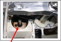
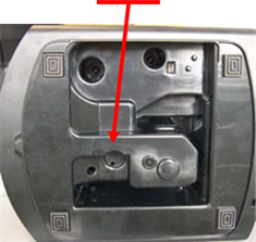
Carry out a cleaning cycle:
If the ejection ram works properly in the tank Î OK
If it sticks, activate manually with a rod inserted through the base:
Check that the drawer switch works properly: any ground coffee in the drawer slide channels could affect the control. If this is the case, remove the technical mount to clean the slide channels. Renew a cleaning cycle.
Determine the reason why clogging-up occurred (see troubleshooting diagnosis table):
- grinder not compliant (quantity of ground coffee)
- electronics setting not compliant with the grinder
- ejection ram stuck in high position
- cake tray replaced partially full
CLEANING AND SCALE REMOVAL CYCLES
- The cleaning light comes on after 350 coffees (or espressos).
- The scale removal light comes on after:
- 12,000 cycles with water hardness setting 0
- 10,000 cycles with water hardness setting 1
- 8,000 cycles with water hardness setting 2
- 6,000 cycles with water hardness setting 3
- 3,000 cycles with water hardness setting 4
with: - 1 coffee (or espresso) = 1 cycle
- 1 "steam" function = 25 cycles (V16 picto power board and V6.8 to 7.0 Visu display) = 40 cycles (V17 picto power board and V7.2 Visu display)
- 1 "hot water" function = 10 cycles
The number of cycles is doubled when a filter is used (progamming in the display version).
PRE-LISTED FAULTS
If the appliance is blocked because of a fault situation, identify the fault with the number displayed:
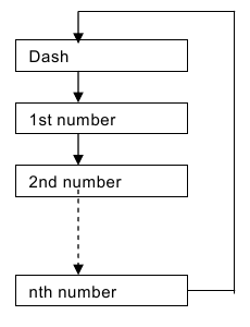
Pictographic model display mode:
- numbers from 1 to 9: fixed display
- number > 9: display of a dash and successively all the numbers.
![]()
| Picto no. | Graph no. | Function | Nature | Servicing |
| 1 | 1 | PosWaterDistrib | The maximum time for the water distributor command has been reached without the tooth being detected | Check operation of distributor switches Check distributor rotation (risk of drop in LV supply if distributor motor current too high). Check for wrong setting or position of motor in the distributor housing |
| 2 | 2 | GroundCoffeeDistrib The maximum time for the ground coffee | distributor has been reached without the ground coffee proportioning switch being detected | Concerns the ground coffee version |
| 3 | 3 | Cycle start conditions | The distributor is in the original position but the actuator is not in the high position + The actuator is in the low position and the actuator switch is still closed |
|
| 4 | 4 | Pump in actuator down phase | During the first seconds of pump start-up, volume is very low | Pump unprimed (start of selfpriming cycle, fault 4 not displayed but recorded in memory of faults in line 6 of A-S mode) Distributor fault Actuator stuck in high positionnot noted up to 5/10/05 |
| 5 | 5 | Pump priming | During the first seconds of pump start-up, volume is zero | Flowmeter fault (wires reversed, connector offset, ...) Drop of water on the flowmeter connector Pump fault Water flow blocked: hose caught, strainer missing (tank valve not actuated), tank badly connected |
| 6 | 6 | Pump in actuator down phase | The flow has not dropped (> 50ml/min) after the actuator has been filled to the maximum (80ml); there is a water leakage and the actuator does not fill | Look for the leakage source: hoses, actuator, priming valve? Flowmeter hoses changed over Distributor problem (leakage at drain..) Faulty connection between the 2 picto boards |
| 7 | 7 | Pump in actuator down phase | The flowmeter signal has dropped (<50ml/min) but the actuator volume is insufficient (<25ml); there is a blockage in the circuit | Ground coffee clogged up: Tamping head stuck Ejector blocked Tank badly connected Hoses caught (pump suction) Fault on the pump switch (component or control via cake tray) Pump priming fault (in presence of filter? coffee-maker stored over a long period without tank or with tank empty?) Water-level board or bundle defective |
| 8 | 8 | Hot water and Coffee Pump | After a certain time of pump control during coffee or water flow, the circuit is considered to be blocked as the water hardly flows at all | Coffee grids plugged Creamy seal plugged Thermoblock plugged |
| 9 | 9 | Time_Setting | A NTC fault is detected; temperature too low or too high | NTC fault (component, bonding, connector, wires...) Coffee leakage on NTC (resistor value) |
| 10 | 0A (10) | Time_Setting | Heating resistor fault detected, heating was started but temperature has not changed | Thermoblock resistor fault (Faulty wiring connections) NTC unstuck NTC cracked |
| | 0B (11) | Spi_TransLCD | During message transmission, the message was not sent since there was no clock at the end of a TimeOut: faulty connection between the 2 boards | Find the bad connection |
| 0C (12) | | Faulty communication between the 2 boards | Disconnect and reconnect the coffee-maker | |
| Distributor blocked, does not turn | Determine the cause | |||
| 0D (13) | Faulty connection between the 2 boards | Find the bad connection | ||
| 0E (14) | Defective power board Faulty connection between the 2 boards | Replace the power board Find the bad connection | ||
| 10 (15) | Defective power board Electromagnetic interference problem (overvoltage...) | Replace the power board Disconnect and reconnect | ||
| FF |
TROUBLESHOOTING DIAGNOSIS & CORRECTIVE ACTIONS
Diagnosing leakages may be facilitated by using cut-outs which can be helpful in supporting the tank and the cake tray.
| DIAGNOSIS | CAUSE | SERVICING | PARTS TO BE CHANGED |
Does not heat | Fuse blown | Identify the cause which led to the fuse blowing
|
|
| NTC defective or poor bonding | Resistor value accurate to 25°C: 100Kohm +/-5% NB: variation of 4 to 5 Kohm for 1°C deviation with respect to 25°C | Thermoblock with NTC | |
| Defective electronics | Electronic circuit | ||
| Resistor cut-out | Thermoblock | ||
| Bad connection | |||
Cuts out | Insulation defect on fuse sheathing | Fuse clusters | |
| Coffee has run onto resistor connectors or the NTC | Identify the cause which led to the coffee leaking | Interface/tank seal | |
Does not flow at coffee outlet | Thermoblock or water circuit scaled up | Remove scale | Replace scaled-up item if scale removal ineffective |
| Thermoblock coffee circuit clogged up by coffee | Carry out 2 to 5 rinsing cycles | ||
| Electronic, distributor or flowmeter fault | Electronic board, distributor or flowmeter | ||
| Coffee grids (high or low) clogged up | Clean | ||
| Creamy seal clogged up or defective | Clean | Creamy seal | |
| Silicone tube bent | Straighten the tube out | ||
| Drain plunger spring badly mounted (plunger blocked) | Remount properly | ||
Water runs into the drip tray during coffee function | Small valve in the drain plunger is not tight (seal missing, clogged up by ground coffee) or is unclipped | Complete drain plunger | |
| Relief valve badly calibrated | Relief valve | ||
Cake crumbly, poor shape, partially dry | Creamy seal allows too much liquid through or not enough | Creamy seal | |
| Ejection ram does not return far enough up |
| ||
Vaporizes during coffee function | Temperature setting too high | Reduce temperature setting | |
| Coffe-maker used at altitude | |||
| NTC not compliant or poor bonding | Replace thermoblock | ||
| Large volume of coffee (220cc) made with grinding which raises pressure | Change in coffee or grinder to be adjusted to coarse grinding | ||
| Any problem leading to a reduction in water flow | |||
| Thermoblock or water circuit scaled up | Remove scale | Replace scaled-up item if scale removal ineffective | |
| Pump flow/pressure specifications not compliant | Pump | ||
| Coffee grids clogged up | Clean | ||
| Silicone tube bent | Straighten the tube out | ||
| Tamping head creamy seal plugged or misshapen | Clean | Creamy seal | |
Volume of coffee in the cup does not comply | Flowmeter defective | Flowmeter | |
| Faulty electronics | Electronic circuit | ||
| Thermoblock or water circuit scaled up? | Remove scale | Replace scaled-up item if scale removal ineffective | |
| A few drops of water drip from the steam nozzle at the beginning of the coffee function | This is a known and accepted phenomenon | ||
| Water runs continuously via the steam nozzle during coffee function | Continuous flow:
| Check flowmeter connections | Flowmeter Electronic boards:
|
| Fit a new water filter in the tank (self-priming phase) | |||
| "Service" key stuck | Change the facing | ||
| Boiling in the tank at the end of the coffee cycle | Poor draining:
| Drain plunger Creamy seal Insert power board with drain time extended from 8 to 10 secs (> V21 picto and > V14 graphic) | |
| Ground coffee clogged up in the chamber | Grinder not compliant Too much ground coffee: cakes >17mm Not enough ground coffee < 6mm | Measure the cake thickness: 12 to 15 mm (11 to 13 mm if grinder new) | Grinder |
| Bad electronics grinding time setting with regards to grinder specifications | Adjust electronics | ||
| Ejection plunger stuck in high position | Identify the cause of sticking:
|
| |
| Ejection ram does not return far enough up |
| Change ejection rod | |
| Cakes placed in columns in the cake tray | Install a modified cake tray with ribbing inside | ||
| Actuator switch short-circuited + 2-cup cycle (grinding without tamping head in the high position) | Change the switch | ||
| Ground coffee blocked between tamping head and grinder spout Bad thermoblock drain | Insert power board with drain time extended from 8 to 10 secs (> V21 picto and > V14 graphic) | ||
| Leakage at tamping head seal level | Check that the tamping head does not catch the grinder spout when it comes back up | Change the seal Change the grinder spout | |
| Coffee grounds collector replaced partially full | |||
| Nozzle overflow at coffee outlet | Temperature too high | See "vaporize" problem | |
| Coffee made after steam preheating without steam actually being produced | |||
| Creamy seal defective | Creamy seal | ||
| Coffee leakage under the thermoblock | "Barista" seal defective or dislodged | Remount the seal Clean the excess of grease in the tank and under the ejection plunger Take up seal slack | "Barista" seal |
| Not enough cream on the coffee | Defective "creamy" seal Steam nozzle adaptor before 15/10/2005 (diam 1.3) | "Creamy" seal Steam nozzle adaptor (diam 1.15) | |
| Faulty draw switch control | Grinder mounting spacer missing the mounting screw goes through the screwing bushing and blocks the draw control | Replace spacer | |
| Minimum level in the tank not detected | Electronic detection circuit positioned too low | Remount the circuit by pulling and slightly tightening the wires | Change the tank receptacle (modified mid-Nov. 2005) |
| Impossible to set the date after unplugging or cut-off in current Display returns to intial date when filter fitted | Fault in the facing visu electronic board | Validate the date when the filter was first fitted. Consequence: there will no longer be any warning message to replace the filter use the index on the top of the filter to memorise the date when the filter was first used | If the customer is demanding, change the visu board. Visu boards concerned by the bug: versions V6.8, V6.9, V7.0 and V7.2 |
| Blue light 0/1 flashes rapidly | Drop in low voltage supply through excessive consumption | Check consumption of distributor motor (distributor opposing torque too high) | Risk of damage to the electronic power board |
AFTER-SALES (A-S) MODE OPERATION
1st-level A-S mode
This mode makes it possible to access information on the rate of use of different coffee-maker functions.
Pictographic model
Access to A-S 1 via combination of the following keys: Service + Strong Coffee key + Mains Connection.
- The Strong Coffee key enables functions to scroll and the Coffee key to return. No signalling.
- Access counter values of the different functions via the Steam key and return via the same Steam key. Signalling via the Calc light.

| d | Function (pictographic model) | Unit |
| 1 | "Coffee" cycle number | unit |
| 2 | "Steam" function number | unit |
| 3 | Cleaning number | unit |
| 4 | Scale removal number | unit |
| 5 | Cleaning & Scale removal warning overrides: Total of number of cycles (coffee or steam) carried out after Cleaning or Scale removal light has come on No zero reset | unit |
| 6 | Writing index of the last fault (0,1,2,3): Depending on the index displayed, consult the corresponding fault in line 7, 8, 9 or 10 See penultimate fault in the previous index (1 if index 2 displayed, 3 if index 0) | code |
| 7 | Index 0 fault | code |
| 8 | Index 1 fault | code |
| 9 | Index 2 fault | code |
| 10 | Index 3 fault | code |
| 11 | Total coffee volume (exclusive of actuator volume and pre-soaking) | mL |
| 12 | Times switched on number | unit |
| 13 | Operating time: ON/OFF light on | min |
| 14 | Rinsing number | unit |
| 15 | Auto cut-off duration, (1,2,3,4,5 hours) | hour |
| 16 | Water hardness (scale removal frequency), (level 0,1,2,3,4) | value |
| 17 | Coffee temperature (level 1,2,3) | value |
| 18 | Cakes in the tray number | unit |
| 19 | Coffee cycles carried out since the last cleaning | cycles |
| 20 | Number of cycles carried out since the last scale removal (coffee, steam, water wieghtings) | cycles |
| 21 | Number of tray emptyings before cleaning of draw | cycles |
| 22 | Extra grinding time added to basic time | 0, 2, 4, 6 or 8 |
| 23 | Flag indicating whether injection of coffee is possible or not (actuator down or not): 1=fault (actuator in low position) | 0/1 |
| 24 | Flag indicating blocking of coffee, steam: positioned if machine cut off during cleaning or scale removal. 1=fault | 0/1 |
| 25 | Software version | code |
| 26 | Production date | dd-mm-yy |
Exit from A-S mode via 0/1 key.
Graphic model
From "Product Information" (Prog + "Product Information" selection + Prog) access to A-S 1 mode via combination of Prog + Water keys.
| d | Function (graphic model) | Unit |
| 1 | Total coffee number | No. |
| 2 | Espresso number | No. |
| 3 | Strong espresso number | No. |
| 4 | Coffee number | No. |
| 5 | Strong coffee number | No. |
| 6 | Double espresso number | No. |
| 7 | Strong double espresso number | No. |
| 8 | Double coffee number | No. |
| 9 | Double strong coffee number | No. |
| 10 | Hot water function number | No. |
| 11 | Steam function number | No. |
| 12 | Rinsing function number | No. |
| 13 | Production date | --/--/-- |
| 14 | First use date | --/--/-- |
| 15 | Graphic software version | Ref. |
| 16 | Power software version | Ref. |
| 17 | Model: (grinder) | Model |
| 18 | Coffee function water volume | ml |
| 19 | Steam function water volume | ml |
| 20 | Times switched on number | Nb |
| 21 | Operating time | min |
| 22 | Temperature level | Number |
| 23 | Water hardness level | Number |
| 24 | Auto cut-off duration | No. Hrs |
| 25 | Hour format | 24 Hrs |
| 26 | Hour | --/-- |
| 27 | Date | --/--/-- |
| 28 | Language | French |
| 29 | Filter present | Absent |
| 30 | Auto-on | Not validated |
| 31 | Measurement unit | |
| 32 | LCD contrast | No. |
| 33 | Cake number | No. |
| 34 | No. coffee since last cleaning | No. |
| 35 | Last error detected. Fault 0A=10, 0B=11, 0C=12, 0D=13, 0E=14, 0F=15 | No. |
Reminder of information available in the Product Information section (see manual)

2nd level A-S mode
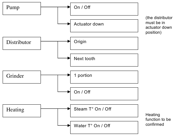
This 2nd level after-sales mode enables control and testing of power items.
Pictographic model (not available)
Graphic model
Access to A-S 2 via OK key + coffee grounds collector removed + mains connection. Access to Controls and Actions by menus and sub-menus in the display Exit from sub-menus via 0/1 key.
POST-SERVICING COMPLIANCY TEST
- Checking correct operation of switches for detecting the presence of draw, cake tray and tank
- Correct coffee operation with measurement of cake thickness (comprised between 11 and 13 mm with new grinder in 60-ml strong espresso function)
- Correct steam operation
- Correct hot water operation
- Cleaning the coffee-maker for delivery
GRAPHIC DISPLAY TEST
Enables presence of all segments to be checked in the display.
Press Prog + water + mains connection and follow carefully the order of operations:
- 0/1 key: figure 1 displayed
- Prog key: figure 2 displayed
- Steam key: figure 3 displayed
- Water key: figure 4 displayed
Turn the selection button in one direction to darken the screen
Turn the selection button in the other direction to remove display
Press OK: the blue light comes on
Documents / ResourcesDownload manual
Here you can download full pdf version of manual, it may contain additional safety instructions, warranty information, FCC rules, etc.
Download Krups Espresseria Automatic XP7200, XP7220, XP7240 Servicing Manual
Advertisement


Need help?
Do you have a question about the XP7200 and is the answer not in the manual?
Questions and answers