Table of Contents
Advertisement
Quick Links
Operation & Maintenance
Manual
Unsafe use of this machine may cause serious injury or
death. Operators and maintenance personnel must read
this manual before operating or maintaining this
machine. This manual should be kept near the machine
for reference and periodically reviewed by all personnel
who will come into contact with it.
NOTICE
Komatsu has had the operating and maintenance in-
structions translated into all the languages of the mem-
ber states in the European Union. Should you wish to
have a version of the operating instructions in another
language, please don’t hesitate to ask at your local
dealer’s.
© 2006 Komatsu Hanomag GmbH
All Rights Reserved
Printed in Europe 07-2006
WA380-
WHEEL LOADER
SERIAL NUMBERS
WARNING
H60051
and up
VEAM440100
6H
Advertisement
Table of Contents

Related Manuals for Komatsu WA380-6H


Summary of Contents for Komatsu WA380-6H
- Page 1 NOTICE Komatsu has had the operating and maintenance in- structions translated into all the languages of the mem- ber states in the European Union. Should you wish to have a version of the operating instructions in another language, please don’t hesitate to ask at your local...
-
Page 3: Foreword
Foreword 1. Foreword WA380-6H – VEAM440100... -
Page 4: Foreword
If you sell the machine, be sure to give this manual to the new owners together with the machine. KOMATSU delivers machines that comply with all applicable regulations and standards of the country to which it has been shipped. If this machine has been purchased in... -
Page 5: Eu Directives
Make sure when installing the antenna that this is installed correctly with good earth connection between antenna and vehicle mass Also observe KOMATSU and manufacturer’s installation instruc- tions for wiring, installation and maximum permitted power con- sumption. WA380-6H – VEAM440100... -
Page 6: Safety Information
When standing up from the operator's seat, always place the work equipment lock lever in the LOCK position. If you accidentally touch the control levers when they are not locked, this may cause a serious injury or death. WA380-6H – VEAM440100... - Page 7 NOTE This word is used for precautions that must be taken to avoid actions which could shorten the life of the machine. REMARK This word is used for information that is useful to know. WA380-6H – VEAM440100...
-
Page 8: Safety Labels
Continuing improvements in the design of this machine can lead to changes in detail which may not be reflected in this manual. Consult KOMATSU or your KOMATSU distributor for the latest available information of your machine or for questions regarding information in this manual. -
Page 9: Introduction
Driving in forward direction, the loader can load or dig material using its attachments intended for loading operations (i.e. bucket). This KOMATSU machine is designed to be used mainly for the following work: Digging work Smoothing... -
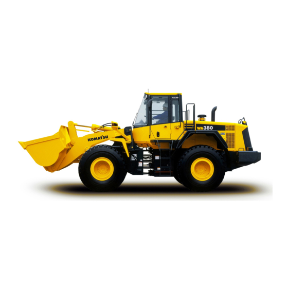
Page 10: Directions Of Machine
Front Bucket Left Right Rear GK032003 In this manual, the directions of the machine (front, rear, left, right) are determined according to the view from the operator's seat in the direction of travel (front) of the machine. WA380-6H – VEAM440100... -
Page 11: Visibility From Operator's Seat
The hatched areas (B) show the areas where the view is blocked when mirrors or other aids to visibility are installed as standard. Please be fully aware that there are places that cannot be seen when operating the machine. GK038002 WA380-6H – VEAM440100... -
Page 12: Necessary Information
1.4 Necessary information Foreword Necessary information When requesting service or ordering replacement parts, please inform your KOMATSU distributor of the following items. 1.4.1 Product Identification Number (PIN)/Machine serial no. plate and position On the center right of the front frame. -
Page 13: Rops/Fops-Cab Serial No. Plate
This plate is located on the right of front axle and on the left of rear axle. GK032007 1.4.5 Transmission serial no. plate This plate is located in travel direction front, above the transmis- sion output. GK032008 1-11 WA380-6H – VEAM440100... -
Page 14: Seat Operator Serial No. Plate
The service meter is displayed on the character display at the bottom center of the machine monitor. GK038005 1.4.8 Table to enter serial no. and distributor Machine serial No. Engine serial No. Product identification number (PIN) Distributor name Address Service Personnel Phone/Fax 1-12 WA380-6H – VEAM440100... -
Page 15: Table Of Contents
Precautions with tires ............2-43 1-13 WA380-6H – VEAM440100... -
Page 16: Contents
Safety belt ............3-93 1-14 WA380-6H – VEAM440100... - Page 17 Precautions for using load and carry method....... 3-138 1-15 WA380-6H – VEAM440100...
- Page 18 (KOMATSU Oil Wear Analysis) ........
- Page 19 1.5 Contents Carrying out KOWA (KOMATSU Oil Wear Analysis) ......4-10 Storing oil and fuel ........... . 4-12 Filters .
- Page 20 Replace injector nozzle tip..........4-89 1-18 WA380-6H – VEAM440100...
- Page 21 Changing the lubrication interval times ........6-36 1-19 WA380-6H – VEAM440100...
- Page 22 Notes ............8-1 1-20 WA380-6H – VEAM440100...
-
Page 23: Dimensions, Weights And Operating Data
Digging depth Overall length, bucket on ground 8,111 Wheel base 3,300 Bucket width 2,916 Width over tyres 2,762 These values refer to machines with 23.5-25 Gauge 2,160 Ground clearance *) Machine without additional counterweight Overall height 3,361 1-21 WA380-6H – VEAM440100... -
Page 24: Ce-Conforming Equipment
423-75-H2D10 5,580 1,481 Bucket WA380-6H 423-71-H2801 5,580 423-75-H2E10 5,760 1,898 423-75-H2D50 3.25 5,850 1,723 423-75-H2D20 3.25 5,850 1,641 423-75-H2D70 3.45 6,210 1,749 423-75-H2D60 3.45 6,210 1,688 423-71-H2900 6,300 423-75-H2D80 6,480 1,909 423-70-H2060 Fork WA380-6H 423-71-H2780 GK032012 1-22 WA380-6H – VEAM440100... -
Page 25: Manufacturer-Supplied Ce-Conforming Equipment, According
(valid in Germany) The dimension Sh (smallest tyre radius) must be added to the dimension D2. The figure G (in kg) represents the maximum load (equipment and operating load) which may act upon this point. GK032013 1-23 WA380-6H – VEAM440100... - Page 26 1.7 CE-Conforming equipment Foreword d1=d2 GK032014 1-24 WA380-6H – VEAM440100...
- Page 27 Bucket connection dimension, bolt (3) for tilt rod Bucket connection dimension d1 - d2, horizontally displaced Driver’s eye Distance: bucket bottom edge - boom bolt hole Vision line Distance: centre of bolt - centre of fastening screw Bolts Tyres 23.5 R25 Bucket 423-75-H2010 1-25 WA380-6H – VEAM440100...
- Page 28 1.7 CE-Conforming equipment Foreword 1-26 WA380-6H – VEAM440100...
-
Page 29: Safety
Safety 2. Safety WARNING Please read and make sure that you fully understand the precautions described in this manual and the safety labels on the machine. When operating or servicing the machine, always follow these precautions strictly. WA380-6H – VEAM440100... -
Page 30: Safety Labels
For details of the part numbers, see this manual or check on the actual part, and order the new part from your KOMATSU distributor. There are also other labels in addition to the safety labels. Han- dle these labels in the same way. -
Page 31: Presentation Of Safety Labels
Safety 2.1 Safety labels 2.1.2 Presentation of safety labels GK032020 GK032018 GK032019 GK032024 GK032025 GK032022 GK032021 GK032023 GK032026 GK032028 GK03202 GK032030 WA380-6H – VEAM440100... - Page 32 2.1 Safety labels Safety GK032020 GK032018 GK032019 GK032025 GK032024 GK032022 GK032021 GK032023 GK032028 GK032026 GK03202 GK032030 WA380-6H – VEAM440100...
- Page 33 Sign indicates to prevere severe injury or death. Honk to alert people nearby. Be sure no one is on or near machine. Use spotter if view is obstructed. Use KOMATSU oil only (421-93-H1390) Do not enter (421-93-H1320) Sign indicates a crush hazard between the articulating parts of the vehicle. Keep away from the vehicle when it is move.
-
Page 34: General Precautions
Always wear a hard hat and safety shoes. If the nature of the work requires it, wear safety glasses, mask, gloves, ear plugs, and safety belt when operating or maintaining the GK032031 machine. Check that all protective equipment functions properly before using it. WA380-6H – VEAM440100... - Page 35 If inspection and maintenance is carried out when the machine is still dirty with mud or oil, there is a hazard that you will slip and fall, or that dirt or mud will get into your eyes. Always keep the machine clean. GK032034 WA380-6H – VEAM440100...
- Page 36 If the control lever is touched by accident, there is danger that the machine may suddenly move and cause serious personal injury. When leaving the machine, lock all parts, and always takes GK038007 the key with you and leave it in the specified place. GK038008 WA380-6H – VEAM440100...
- Page 37 No people on attachments Never let anyone ride on the work equipment, or other attach- ments. There is a hazard of falling and suffering serious injury. WA380-6H – VEAM440100...
- Page 38 Even when the oil has cooled down, loosen the plug slowly to relieve the internal pressure before removing the plug. GK032043 2-10 WA380-6H – VEAM440100...
- Page 39 Fire caused by accumulation of flammable material. Remove any dry leaves, chips, pieces of paper, dust, or any other flammable materials accumulated or affixed around the engine, exhaust manifold, muffler, or battery, or inside the undercovers. 2-11 WA380-6H – VEAM440100...
- Page 40 Turn the start switch OFF to stop the engine. Use the handrails and steps to get off the machine. Window washer liquid Use an ethyl alcohol base washer liquid. Methyl alcohol base washer liquid may irritate your eyes, so do not use it. 2-12 WA380-6H – VEAM440100...
- Page 41 Unauthorized modification If this machine is modified without permission from KOMATSU, there is danger that problems may occur with safety and that this may lead to serious personal injury. Modifications may have an adverse effect on items such as machine strength and visibility.
- Page 42 Before starting operations, take steps to ensure that the ground is safe and to prevent the machine from rolling over or falling. 2-14 WA380-6H – VEAM440100...
- Page 43 If the machine should come too close or touch the electric cable, to prevent electric shock, the operator should not leave the operator's compartment until it has been confirmed that the electricity has been shut off. Also, do not let anyone come close to the machine. 2-15 WA380-6H – VEAM440100...
- Page 44 If it is necessary to start the engine or run the machine inside a building or underground, where the ventilation is poor, take steps to remove the exhaust gas and bring in ample fresh air. GK032048 2-16 WA380-6H – VEAM440100...
- Page 45 Always observe the rules and regulations for the work site and environmental standards. This machine does not use asbestos, but there is a danger that imitation parts may contain asbestos, so always use genuine KOMATSU parts. 2-17 WA380-6H – VEAM440100...
-
Page 46: Precautions For Operation
Adjust the mirrors so that the rear of the machine can be seen clearly from the operator's seat. See "Adjusting mirrors (3-95)". Check that there are no persons or obstacles above, below, or in the area around the machine. 2-18 WA380-6H – VEAM440100... - Page 47 Before charging or starting the engine with a different power source, melt the battery electrolyte and check that there is no leakage of electrolyte before starting. 2-19 WA380-6H – VEAM440100...
-
Page 48: Operation
If any abnormality is found, carry out repairs immediately. Before driving the machine or starting operations, check that safety bar (1) is securely fixed at the FREE position. Free Lock GK038011 2-20 WA380-6H – VEAM440100... - Page 49 Take special care not to hit other machines or people when turning or swinging the machine. Always be sure to carry out the above precautions even when the machine is equipped with mirrors. GK032053 2-21 WA380-6H – VEAM440100...
- Page 50 This may cause the tires to burst. If a tire bursts, it produces an extremely large destruc- tive force, and this may cause serious injury or accident. If you are going to travel continuously, please consult your KOMATSU distributor. 2-22 WA380-6H – VEAM440100...
- Page 51 When traveling up or down hills with a loaded bucket, always travel with the bucket facing uphill. If the machine travels with the bucket facing downhill, there is danger that the machine may tip over. 2-23 WA380-6H – VEAM440100...
- Page 52 When the engine is not running, you can lower the work unit by means of the lift arm control lever. 1. Turn the key in ignition switch (1) to ON. 2. Then slowly press the lift arm control lever (2) forward to the "LOWER" position. GK038012 2-24 WA380-6H – VEAM440100...
- Page 53 If the work equipment is suddenly lowered or suddenly stopped, the reaction may cause the machine to tip over. Particularly when carrying a load, be sure to operate the GK032062 work equipment carefully. 2-25 WA380-6H – VEAM440100...
- Page 54 Reduce the speed and use the engine as a brake while applying the foot brake intermittenly (depress the brake intermittenly several times). If nessecary, lower the bucket to the ground to stop the machine. 2-26 WA380-6H – VEAM440100...
- Page 55 GK038007 Adhere to all regulations on parking vehicles and securing building sites GK038008 If it is necessary to park the machine on a slope, set blocks under the wheels to prevent the machine from moving. GK032065 2-27 WA380-6H – VEAM440100...
-
Page 56: Transportation
Transportation The machine can be divided into parts for transportation, so when transportating the machine, please contact your KOMATSU distributor to have the work carried out. Loading and unloading When loading or unloading the machine, mistaken operation may bring the hazard of the machine tipping over or falling, so particular care is necessary. - Page 57 Lock the frame with the safety bar to prevent the machine from articulating. Fit chains to the front frame and the rear frame to hold the machine securely in position. For details of the shipping procedure, see "Transportation procedure (3-140)". 2-29 WA380-6H – VEAM440100...
-
Page 58: Battery
Flammable hydrogen gas is generated when the battery is charged, so remove the battery from the chassis, take it to a well-ventilated place, and remove the battery caps before charging it. Tighten the battery caps securely. Install the battery securely to the determined place. 2-30 WA380-6H – VEAM440100... - Page 59 When connecting a normal machine to a problem machine with booster cables, always use a normal machine with the same battery voltage as the problem machine. For details of the starting procedure when using booster cables, see "Starting engine with booster cable (3-162)". 2-31 WA380-6H – VEAM440100...
-
Page 60: Towing
GK032072 Move the machine slowly and be sure not to apply any sud- den load on the wire rope. Connect a wire rope to the part indicated with the arrow in the diagram at right. GK038013 2-32 WA380-6H – VEAM440100... -
Page 61: Precautions For Maintenance
Appoint leader when working with others When repairing the machine or when removing and installing the work equipment, appoint a leader and follow his instructions dur- ing the operation. When working with others, misunderstandings between workers can lead to serious accidents. 2-33 WA380-6H – VEAM440100... - Page 62 OFF position. GK038014 Free Lock GK038007 Set parking brake switch (3) to the ON position, then put blocks under the front and the rear of the tires. GK038008 GK050018 2-34 WA380-6H – VEAM440100...
- Page 63 (2) to the ON position to prevent the machine from moving. Free Do not touch any control levers. If any control lever must be Lock operated, give a signal to the other workers to warn them to move to a safe place. GK038007 GK038008 2-35 WA380-6H – VEAM440100...
- Page 64 Do not make holes in it, weld it, or use a cutting torch. Do not hit or roll the accumulator, or subject it to any impact. GK032078 When disposing of the accumulator, the gas must be released. Please contact your KOMATSU distributor to have this work performed. 2-36 WA380-6H – VEAM440100...
- Page 65 Free With the engine switched off, lower the boom slowly until it rests on the supporting prop. Lock Set the control lever to "NEUTRAL" and secure it with the work equipment lock lever (2) (locked). GK038007 2-37 WA380-6H – VEAM440100...
- Page 66 Removing battery terminal When repairing the electrical system or when carrying out elec- trical welding, remove the negative (-) terminal of the battery to prevent the flow of current. 2-38 WA380-6H – VEAM440100...
- Page 67 Do not remove the E.C.S.S. piping or components. If it is necessary to remove them, please ask your KOMATSU distributor to carry out the removal operation. Precautions for high-pressure fuel High pressure is generated inside the engine fuel piping when the engine is running.
- Page 68 Never touch the injector terminal or the inside of the engine controller. If it is necessary to touch the injector terminal or the inside of the engine controller, please contact your KOMATSU distributor. GK043102 2-40...
- Page 69 When carrying out cleaning with compressed air, there is a hazard of serious injury caused by flying particles. When using compressed air to clean elements or the radia- tor, always wear safety goggles, dust mask, gloves, and other protective equipment. 2-41 WA380-6H – VEAM440100...
- Page 70 Replace or repair safety-critical parts if any defect is found, even when they have not reached the time specified interval. Replace all hoses every 2 years at the latest. The shelf life of the hose should not exceed 2 years. 2-42 WA380-6H – VEAM440100...
-
Page 71: Precautions With Tires
To maintain safety, always do as follows. Maintenance, disassembly, repair, and assembly of the tires and rims requires special equipment and special technology, so always ask your KOMATSU distributor to carry out these operations. GK032084 Inflate tyres up to the defined pressure. If the tyre pressure is too low, the tyres may heat up and burst. - Page 72 2.5 Precautions with tires Safety 2-44 WA380-6H – VEAM440100...
-
Page 73: Operation
Operation 3. Operation WARNING Please read and make sure that you understand the SAFETY section before reading this section. WA380-6H – VEAM440100... -
Page 74: General View
(8) Turn signal lamp (2) Tilt lever (9) Head lamp (3) Front wheel (10) Lift cylinder (4) Bucket cylinder (11) Lift arm (5) Front working lamp (12) Rear working lamp (6) ROPS cab (13) Rear combination lamp (7) Rear wheel WA380-6H – VEAM440100... -
Page 75: General View Of Controls And Gauges
(11) Hazard lamp switch (23) Right brake pedal (12) Lamp switch (24) Steering tilt lock lever (12) Turn signal lever (25) Left brake pedal (12) Dimmer switch (26) Work equipment lock lever (*) E.C.S.S.: Electrically Controlled Suspension System WA380-6H – VEAM440100... - Page 76 3.1 General view Operation Front switch panel GK038016 (1) Monitor panel mode selector switch 1 (2) Monitor panel mode selector switch 2 (3) Front working lamp switch (4) Rear working lamp switch WA380-6H – VEAM440100...
- Page 77 (3) Transmission cut-off set switch (4) Directional selector switch actuation switch (5) Emergency steering switch (Option) (6) Engine power mode selector switch (7) Torque converter lock-up switch (Option) (8) Cooling fan reverse rotation switch (9) Starting switch WA380-6H – VEAM440100...
- Page 78 (18) Output mode pilot lamp (power mode) (39) Fuel level caution lamp (19) Preheating pilot lamp (40) Fuel gauge (20) Semi auto digging pilot lamp (Option) (41) Economy operation display lamp (21) Auto-greasing pilot lamp (Option) (*) Machines eqipped with KOMTRAX WA380-6H – VEAM440100...
-
Page 79: Explanation Of Components
The indicator gauges and meters are actuated after the above system check is completed. The character display shows “KOMATSU“ for 3 seconds. If the lamps do not light up, there is probably a failure or discon- nection, so contact your KOMATSU distributor for inspection. -
Page 80: Types Of Warning
“E02“ is displayed on character display (1). REMARK The alarm buzzer sounds in a 1.6 second cycle. (0.8 sec. “ON“ -> 0.8 sec. “OFF“) (The same cycle for ON, OFF) WA380-6H – VEAM440100... -
Page 81: Central Warning Lamp
This display portion (1) lights up if any emergency stop item, caution item, or mistaken operation of any switch or lever occurs. At the same time, the alarm buzzer sounds. Check the content of the display and carry out the specified action for the item. GK038005 WA380-6H – VEAM440100... -
Page 82: Character Display Portion
Information regarding the failure of the machine or maintenance is displayed on the character display when the starting switch is at the ON position, check the display to confirm that there is no abnormality before starting to travel. 3-10 WA380-6H – VEAM440100... - Page 83 If action code E03 is displayed, stop the machine immediately and check the failure code. For details, see "Failure code display (3-13)". Inform your KOMATSU distributor of the failure code and ask for repairs. If there is a failure on the machine, or it is necessary to change...
- Page 84 3.2 Explanation of components Operation E03: When this code is displayed, stop the machine immedi- ately, check the failure code, and contact your KOMATSU dis- E 0 3 tributor for repairs. C H E C K R I G H T...
- Page 85 If an action code is displayed on the character display, check the failure code according to the failure code display method given below. When contacting your KOMATSU distributor to request repairs, please inform your distributor of the failure code. Method of displaying failure code 1.
- Page 86 1000 CORR RES Transmission oil 1000 TM OIL Transmission oil filter 1000 TM FILT Hydraulic filter 2000 HYD FILT Hydraulic tank breather element 2000 HYD BREATH Hydraulic oil 2000 HYD OIL Axle oil 2000 AXLE OIL 3-14 WA380-6H – VEAM440100...
- Page 87 "Change oil in hydraulic tank, replace hydraulic filter element (4-76)" Hydraulic tank breather element "Replace hydraulic tank breather element (4-79)" Hydraulic oil "Change oil in hydraulic tank, replace hydraulic filter element (4-76)" Axle oil "Change axle oil (4-80)" 3-15 WA380-6H – VEAM440100...
-
Page 88: Emergency Stop Item
GK038018 (1) Brake oil pressure caution lamp (2) Engine oil pressure caution lamp (3) Battery charge circuit caution lamp (4) Steering oil pressure caution lamp 3-16 WA380-6H – VEAM440100... - Page 89 At the same time, the top line of the character display displays “E03“ and the bottom line displays “CHECK RIGHT NOW“ and “CALL“ alternately for 3 seconds each, so stop the machine immediately in a safe place, stop the engine, and carry out inspection. 3-17 WA380-6H – VEAM440100...
- Page 90 At the same time, the top line of the character display displays “E03“ and the bottom line displays “CHECK RIGHT NOW“ and “CALL“ alternately for 3 seconds each, so stop the machine immediately in a safe place, stop the engine, and carry out inspection. 3-18 WA380-6H – VEAM440100...
-
Page 91: Caution Items
If these lamps light up, stop operations quickly and carry out the following action. GK038018 (1) Axle oil temperature caution lamp (2) Torque converter oil temperature caution lamp (3) Engine coolant temperature caution lamp (4) Hydraulic oil temperature caution lamp (5) Fuel level caution lamp 3-19 WA380-6H – VEAM440100... - Page 92 At the same time, “E02“ is displayed on the top line of the char- acter display and “TC OVERHEAT“ is displayed on the bottom line. Stop the machine and run the engine under no load at a mid-range speed until the lamp goes out. 3-20 WA380-6H – VEAM440100...
- Page 93 If it lights up, check and add fuel as soon as possible. For details, see "Check fuel level, add fuel (3-90)". REMARK Even if the caution lamp lights up, action code “E02“ is not dis- GK032101 played on the character display. 3-21 WA380-6H – VEAM440100...
-
Page 94: Inspection And Maintenance Item
(3) Battery electrolyte level caution lamp (Option) (4) Maintenance caution lamp (5) Air cleaner clogging caution lamp (*) (6) Transmission oil filter clogging caution lamp (7) Fuel filter water detection caution lamp (*) Machines eqipped with KOMTRAX 3-22 WA380-6H – VEAM440100... - Page 95 During checks before starting, if the engine is started with the engine oil level caution lamp lighted up, the lamp will stay lighted Stop the engine, check the oil level in the engine oil pan, and add oil. 3-23 WA380-6H – VEAM440100...
- Page 96 For details of the items covered by filter and oil replacement, see "Filter, oil replacement time display (3-14)". After replacing the filter or changing the oil, reset time for the replacement. For details, see "Reset method for filter, oil replacement time (3-35)". 3-24 WA380-6H – VEAM440100...
- Page 97 7. Fuel filter water detection caution lamp This lamp (7) lights up if water accumulates in the water separa- tor installed to the fuel pre-filter. If it lights up, check the pre-filter. For details, see "Replace fuel pre-filter cartridge (4-68)". GK050032 3-25 WA380-6H – VEAM440100...
-
Page 98: Pilot Display Portion
(11) Shift indicator (12) Auto-shift pilot lamp (13) Torque converter lockup pilot lamp (Option) (14) Shift hold pilot lamp (15) Shift lever position pilot lamp (16) Turn signal pilot lamp (17) Head lamp high beam pilot lamp 3-26 WA380-6H – VEAM440100... - Page 99 In addition, the lamp flashes if the emergency steering is actu- ated continuously for one minute. At the same time, “E02 EMR S/T OVERRUN“ is displayed on the character display, so move the machine immediately to a safe place, stop the engine, and check the condition. 3-27 WA380-6H – VEAM440100...
- Page 100 The preheating time differs according to the engine water tem- perature. GK032108 For details, see "Starting engine (3-98)". 6. Semi auto digging pilot lamp (Option) This lamp (6) is not used. GK050040 7. Auto-greasing pilot lamp (Option) This lamp (7) is not used. GK050033 3-28 WA380-6H – VEAM440100...
- Page 101 GK050039 11. Shift indicator This indicator (11) indicates the transmission gear range (actual travel speed range). GK043113 3-29 WA380-6H – VEAM440100...
- Page 102 This lamp (15) displays the transmission position of the gearshift lever. When auto shift has been selected, it shows the maximum speed range selected by the automatic transmission. The maxi- mum speed range can be selected by the shift-up switch and shift-down switch. GK043117 3-30 WA380-6H – VEAM440100...
- Page 103 17. Head lamp high beam pilot lamp This lamp (17) lights up when the head lamp is at high beam. When the dimmer switch is used to set the head lamp to high beam, the pilot lamp lights up. GK032112 3-31 WA380-6H – VEAM440100...
-
Page 104: Meter Display Portion
3.2 Explanation of components Operation Meter display portion GK038018 (1) Torque converter oil temperature gauge (2) Engine cooling water temperature gauge (3) Hydraulic temperature gauge (4) Fuel gauge (5) Speedometer (6) Meter display pilot lamp 3-32 WA380-6H – VEAM440100... - Page 105 In addition, “E02“ is displayed on the top line of the character display and “HYD OVERHEAT“ is displayed on the bottom line. Run the engine under no load at a mid-range speed and wait until the indicator goes down to white range (A). 3-33 WA380-6H – VEAM440100...
- Page 106 It is also possible to display the engine speed by switching meter (5). If you wish to switch between the speedometer and tachometer, please contact your KOMATSU distributor to have it switched. GK032116 6. Meter display pilot lamp This lamp (6) displays the unit for the travel speed or engine tachometer.
-
Page 107: Other Functions Of Machine Monitor
4. Press the (>) or (<) of monitor panel mode selector switch 2 to display the item (filter or oil) which has reached the replacement time. 3-35 WA380-6H – VEAM440100... - Page 108 1. 7. When resetting the replacement time for another item, carry out the procedure from Step 4. After completing, press (') of monitor panel mode selector switch 1 twice or turn the starting switch OFF. 3-36 WA380-6H – VEAM440100...
- Page 109 (#) of monitor panel mode selector switch 1 to return to the previous screen. 6. When completing the operation, press (#) of monitor panel mode selector switch 1 twice or turn the starting switch OFF. 3-37 WA380-6H – VEAM440100...
- Page 110 To abort, set the cursor at “NO“, then press the (') of machine monitor mode selector switch 1. 6. When completing the operation, press (') of monitor panel mode selector switch 1 twice or turn the starting switch OFF. 3-38 WA380-6H – VEAM440100...
- Page 111 1. The brightness will be selected and the screen will return to the previous screen. 7. When completing the operation, press (#) of monitor panel mode selector switch 1 twice or turn the starting switch OFF. 3-39 WA380-6H – VEAM440100...
-
Page 112: Switches
3.2 Explanation of components Operation 3.2.2 Switches GK038020 3-40 WA380-6H – VEAM440100... - Page 113 (21) E.C.S.S. switch (*) (Option) (22) Emergency steering switch (Option) (23) Cooling fan reverse rotation switch (24) Directional selector switch (25) Directional selector actuation switch (26) Torque converter ock up switch (Option) (*) E.C.S.S.: Electrically Controlled Suspension System 3-41 WA380-6H – VEAM440100...
- Page 114 Set to the Power mode when carrying out heavy-duty digging operations of rock or operations where the speed is required, or when traveling at high speed on flat ground or on slopes. 3-42 WA380-6H – VEAM440100...
- Page 115 This is effective in reducing fuel consumption. For details of the manual shift, see "Manual shift (3-58)". For details of the auto-shift, see "Automatic shift (3-59)". 3-43 WA380-6H – VEAM440100...
- Page 116 Position (a): ON Cut-off position can be adjusted When the switch is released, it automatically returns to its origi- nal position. For details of the method of adjusting the cut-off position, see "Adjusting transmission cut-off position (3-116)" 3-44 WA380-6H – VEAM440100...
- Page 117 This switch (6) is used to switch the head lamps between high beam and low beam. When the head lamps are at high beam, the high beam pilot lamp lights up. Position (a): Low beam Position (b): High beam GK043124 3-45 WA380-6H – VEAM440100...
- Page 118 GK043126 machine breaks down and has to be parked on the road. Position (a): Turn signal lamps, turn signal pilot lamp flash, and pilot lamp (C) lights up at same time. Position (b): Lamps are OFF. 3-46 WA380-6H – VEAM440100...
- Page 119 Apply the parking brake only after the machine has stopped. If the parking brake has been used as an emergency brake when traveling at high speed, contact your KOMATSU dis- tributor to have the parking brake checked for any abnormal- ity.
- Page 120 If position (a) is pressed, the pilot lamp will light up and the work- ing lamp circuit will be switched ON. If the lamp switch is not at the ON position for the side clearance lamp or head lamp, the working lamp will not light up. 3-48 WA380-6H – VEAM440100...
- Page 121 Press here to go on to the next screen, or to move the cursor for- GK038029 ward, or to increase the number when entering numerals Position (<): Press here to go back to the previous screen, or to move the cursor back, or to reduce the number when entering numerals 3-49 WA380-6H – VEAM440100...
- Page 122 When canceling the shift hold, operate the directional lever or gearshift lever or operate the transmission shift mode selector switch to MANUAL. It is also possible to cancel the hold shift by turning the starting switch OFF. GK038031 3-50 WA380-6H – VEAM440100...
- Page 123 18. Cigarette lighter This is used to light cigarettes. After cigarette lighter (18) is pushed in, it will return to its original position after a few seconds, then you may pull it out and light a cigarette. GK032135 3-51 WA380-6H – VEAM440100...
- Page 124 When carrying out inspection and maintenance, first lower the work equipment to the ground, then turn the E.C.S.S. switch OFF before starting the inspection and maintenance operation. When carrying out leveling work, turn the E.C.S.S. switch OFF. 3-52 WA380-6H – VEAM440100...
- Page 125 The time for operating the emer- gency steering continuously is a maximum of 60 seconds. When using the emergency steering, travel at a speed of less than 5 km/h (3.1 MPH). For details, see "Emergency steering (3-118)". 3-53 WA380-6H – VEAM440100...
- Page 126 For details of the procedure for cleaning, see "Clean radiator fins and cooler fins (4-43)". Position (c): Neutral (OFF) The cooling fan is constantly set to normal rotation. Run the engine at idling when operating the switch. 3-54 WA380-6H – VEAM440100...
- Page 127 Position (a): ON The directional selector switch is actuated. The directional selector pilot lamp on the machine monitor lights Position (b): OFF GK038037 The directional selector switch is turned off. 3-55 WA380-6H – VEAM440100...
- Page 128 While the lock-up is GK038038 engaged, the lock-up pilot lamp on the machine monitor lights Position (b): OFF The lock-up does not function. For details, see "Handling torque converter lock-up (6-3)" 3-56 WA380-6H – VEAM440100...
-
Page 129: Control Levers, Pedals
3.2 Explanation of components 3.2.3 Control levers, pedals GK038016 (1) Gearshift lever (2) Directional lever (3) Gearshift lever stopper (4) Work equipment lock lever (5) Bucket control lever (6) Lift arm control lever (7) Brake pedal (8) Accelerator pedal 3-57 WA380-6H – VEAM440100... - Page 130 (A), (B), (C)). To adjust the length, remove the screw (E) at the bottom of the lever knob (D), slide the knob to the desired posi- tion, then tighten the screw (E) again. (The lever is installed to position (B) when it is shipped from the factory.) GK043143 3-58 WA380-6H – VEAM440100...
- Page 131 Shift gear with the gearshift lever. GK038030 REMARK When the transmission has been shifted down from 2nd to 1st with the kickdown switch, it will shift up from 1st to 2nd when the travel speed increases. 3-59 WA380-6H – VEAM440100...
- Page 132 (The lever is installed to position (B) when it is shipped from the factory.) GK043143 3. Gearshift lever stopper This stopper (3) prevents the gearshift lever from entering the 3rd or 4th positions when working. Position (a): Stopper actuated. Position (b): Stopper released. GK043145 3-60 WA380-6H – VEAM440100...
- Page 133 LOCK position (L). Lock REMARK If the work equipment lock lever is at the LOCK position, the work equipment will not move even when the work equipment control lever is operated. GK038007 3-61 WA380-6H – VEAM440100...
- Page 134 The lift arm moves freely under external force. Lower GK032142 REMARK If the engine is stopped or the work equipment lock lever is at the LOCK position, the lever does not stop at the detent position. 3-62 WA380-6H – VEAM440100...
- Page 135 8. Accelerator pedal This pedal (8) controls the engine speed and output. The engine speed can be freely controlled between low idling and full speed. GK038041 3-63 WA380-6H – VEAM440100...
-
Page 136: Steering Tilt Lock Lever
Lock GK043020 Up-down When at When moved up to movement 0 mm (0 in) 40 mm (1.6 in) 0 - 105 mm 0 - 130 mm Tilt amount (0 - 4.1 in) (0 - 5.1 in) 3-64 WA380-6H – VEAM440100... -
Page 137: Cap With Lock
Position (a): OPEN Position (b): LOCK GK043148 To lock the cap 1. Screw the cap into place. 2. Turn the starting switch key to LOCK position (b), then remove the key. GK043149 3-65 WA380-6H – VEAM440100... -
Page 138: Safety Bar
When locking the safety bar, lock it as follows. 1. Insert safety lock pin (1) securely into hinge (2) at the bottom of the front frame. 2. Always secure it with supplied linchpin (3). GK050088 3-66 WA380-6H – VEAM440100... -
Page 139: Towing Pin
After using it, wipe off the grease from its outside and install it in position. Insert the grease pump in the holder and fix it with the rubber band. Hitch the tail chain of the grease pump to the hook at the bottom of the holder. GK038044 3-67 WA380-6H – VEAM440100... -
Page 140: Cab Door
GK038045 4. When closing the door from the operator's seat, push knob (2) to release the catcher. 5. When closing the door after getting off the machine, pull knob (3) down to release the catcher. GK038046 3-68 WA380-6H – VEAM440100... -
Page 141: Cab Window Open Lock
Pull open lock knob (1) towards the inside of the machine to release the lock, push open-lock knob (1) up along the rail to move to the lock position, then release the knob. There are 2 lock positions: open and closed. GK038049 3-69 WA380-6H – VEAM440100... -
Page 142: Reset Right Window Open Lock For Escape
3.2.12 Backup alarm This sounds an alarm when the directional lever is set to the R position. It is used to warn people behind the machine that the machine will travel in reverse. 3-70 WA380-6H – VEAM440100... -
Page 143: Fuse
Load meter printer (Option) Air conditioner B Air conditioner A Wiper, washer (10) Backup lamp,brake lamp Work equipment positioner, Work equip- (11) ment controller A (Option) (12) Emergency steering (Option) (13) Parking brake (14) Transmission control A (15) Horn 3-71 WA380-6H – VEAM440100... -
Page 144: Slow Blow Fuse
ON, the slow blow fuse may be blown. Check and replace it. The slow blow fuse is beside the engine on the left side of the machine. Slow blow fuse Permanent power source Main power A GK038053 Main power B Heater relay 120A (electrical intake air heater) 3-72 WA380-6H – VEAM440100... -
Page 145: Power Outlet
When cigarette lighter (1) is removed, the lighter socket can be used as a 24V power source. Maximum amperage: 9A (216W) GK038054 Electric power source (2) can be used as a 12V power source. (Option) Maximum amperage: 10A (120W) GK038055 3-73 WA380-6H – VEAM440100... -
Page 146: Air Conditioner
General locations and function of control panel FACE FACE FOOT FOOT GK038056 (1) Main power switch (2) Fan switch (3) Air conditioner switch (4) Temperature control switch (5) FRESH/RECIRC selector switch (6) Display monitor 3-74 WA380-6H – VEAM440100... - Page 147 GK038059 The setting for the air flow is displayed on the display monitor. A: Monitor display B: Air flow a: Air flow “Lo“ b: Air flow “M1“ c: Air flow “M2“ d: Air flow “Hi“ GK038060 3-75 WA380-6H – VEAM440100...
- Page 148 When switch (A) is pressed, the temperature of the air blowing out becomes higher; when switch (B) is pressed, the tempera- ture of the air blowing out becomes lower. The setting (C) for the temperature is displayed on the display monitor. GK038064 GK038065 3-76 WA380-6H – VEAM440100...
-
Page 149: Method Of Operation
If it freezes and no cold air comes out, turn the air conditioner switch OFF, raise the temperature setting, run the air conditioner with the air flow at “Hi “ for a short time, then turn the air condi- tioner switch ON again. 3-77 WA380-6H – VEAM440100... - Page 150 GK038066 4. Press RECIRC/FRESH selector switch (4) to select FRESH. 5. Press air conditioner switch (5) to turn the air conditioner REMARK When the outside temperature is below 0°C, the air conditioner (compressor) may not operat 3-78 WA380-6H – VEAM440100...
-
Page 151: Precautions When Using
When adding refrigerant or carrying out other maintenance, spe- cial tools and instruments are needed, so ask your KOMATSU distributor to carry out inspection and repair. 3-79 WA380-6H – VEAM440100... -
Page 152: Cool Box
(1) is angled with the wiper blade (2) locked to the arm (the bottom of the blade is caught on the arm), abnormal force is brought to bear on the mounting bracket and the bracket may break. GK032173 3-80 WA380-6H – VEAM440100... -
Page 153: Operation
Leakage of fuel or oil will cause the machine to catch fire. Check carefully, and be sure to repair any abnor- malities, or please contact your KOMATSU distributor. Always repair any damage to the handrails and steps, and tighten any loose bolts. - Page 154 9. Check for loose air cleaner mounting bolts. Check for the loose bolts, and if loose, tighten up. 10. Check for loose battery terminals. Tighten any loose terminal. 3-82 WA380-6H – VEAM440100...
- Page 155 Deteriorated, deformed or abnormally damaged tires which do not seem usable 15. Inspect rims. WARNING Check the rims (wheels) and rings for deformation, corrosion and cracks. In particular, check the side rings, lock rings and rim flanges thoroughly. 3-83 WA380-6H – VEAM440100...
-
Page 156: Check Before Starting
2 seconds and the alarm buzzer sounds for approx. 2 sec. If the lamps do not light up, there is probably a failure or dis- connection. Contact your KOMATSU distributor for inspec- tion. GK038005 3-84... - Page 157 (1). If the volume of coolant added is more than usual, check for possible leakage. Confirm that there is no oil in the coolant. GK032181 3-85 WA380-6H – VEAM440100...
- Page 158 When checking the oil level after the engine has been operated, wait for at least 15 minutes after stopping the engine before checking. If the machine is at an angle, make it horizontal before checking. GK032178 3-86 WA380-6H – VEAM440100...
- Page 159 5. On this machine, sensor (5) is installed to detect if water is accumulated at the bottom of the fuel pre-filter. If water separator caution lamp (6) on the machine monitor lights up, carry out the above Steps 1 - 4 to drain the water. 3-87 WA380-6H – VEAM440100...
- Page 160 If transparent cap (3) is dirty and the contents cannot be easily seen, clean transparent cap (3) when replacing the fil- ter. When washing, if plug (2) is removed, coat the O-ring with grease, then tighten by hand until it contacts the bottom. 3-88 WA380-6H – VEAM440100...
- Page 161 In addition, dirt stuck to the element will drop inside the inner element more frequently during the cleaning operation. 3-89 WA380-6H – VEAM440100...
- Page 162 (F) until the fuel tank is full. For details of the method for opening and closing the cap, see "Cap with lock (3-65)". 3. After adding fuel, tighten the cap securely. Fuel tank capacity: 300 liters GK038074 3-90 WA380-6H – VEAM440100...
- Page 163 CAUTION If fuses are frequently blown or if there are traces of short-circuit- ing on the electrical wiring, promptly ask your KOMATSU distrib- utor to locate the cause and make the repair. Keep the top surface of the battery clean and check the breather hole in the battery cap.
-
Page 164: Adjustment
Careful! No height adjustment. (E) Lumbar support Push buttons to inflate/deflate the air chambers of the integrated pneumatic system. This allows the operator to match the shape of the backrest indi- vidually to the body contours. 3-92 WA380-6H – VEAM440100... -
Page 165: Safety Belt
The belt cannot be pulled out unless it is completely wound GK015036 Taking off the safety belt Press the orange button to release the lock of the safety belt and allow the belt to wind up. 3-93 WA380-6H – VEAM440100... - Page 166 Adjust lever stand forward and backward Pull lever (1) up with your left hand, grip wrist rest (3) with your right hand and move it to the front or rear, then release lever (1). Amount of adjustment: 180 mm. GK038076 3-94 WA380-6H – VEAM440100...
- Page 167 GK038079 Tightening torque Mirrors A, B: 2.0 to 2.5 Nm Mirrors C: 8.8 to 9.8 Nm If the tightening torque cannot be controlled, ask your KOMATSU distributor for tightening the bolts. 3-95 WA380-6H – VEAM440100...
- Page 168 Operate the work equipment control lever to lower the " bucket to the ground. GK032064 Check that the work equipment control lever is at the " HOLD position, then set the safety lock lever to the LOCK position. 3-96 WA380-6H – VEAM440100...
- Page 169 2 seconds, and the alarm buzzer sounds for approx. 2 sec. If any monitor does not light up, there is probably a failure or disconnection, so contact your KOMATSU distributor for GK038021 inspection. In addition, after all the monitors, gauges, and central warn- ing lamp light up, a self check is carried out to check that the emergency steering function works properly.
- Page 170 If the ambient temperature is low, the preheating pilot lamp (2) lights up and automatic preheating is carried out. Keep the key in starting switch (1) at the ON position until the pre- heating pilot lamp (2) goes out. GK038021 3-98 WA380-6H – VEAM440100...
- Page 171 The key will automatically return to the ON position (B). REMARK Keep the accelerator pedal depressed after the engine starts up, until engine warming-up run is finished. Do not step on the pedal to the full stroke. GK038021 3-99 WA380-6H – VEAM440100...
- Page 172 The time that the preheating pilot lamp (2) stays lighted up depends on the ambient temperature as shown in the table Ambient on the right. Lighting time temperature 0 seconds to -1°C to -15°C 30 seconds -15°C or less 30 seconds 3-100 WA380-6H – VEAM440100...
- Page 173 When the engine starts, if the water temperature is 30°C or less, the warming-up operation (engine speed: 1000 rpm) is automat- ically carried out. The warming-up operation is automatically cancelled when the water temperature reaches 50°C or more. (Engine speed: 850 rpm) Water temperature (°C) GK038081 3-101 WA380-6H – VEAM440100...
- Page 174 Breaking-in the machine CAUTION Your KOMATSU machine has been thoroughly adjusted and tested before shipment. However, operating the machine under severe conditions at the beginning can adversely affect the per- formance and shorten the machine life.
- Page 175 With this operation, the oil will reach the relief pressure and this will warm up the hydraulic oil more quickly. 5. Slowly operate the steering wheel to the left and the right about 10 minutes to warm up the hydraulic oil inside the steering valve. 3-103 WA380-6H – VEAM440100...
- Page 176 Select the oil from the table of recommended oils below accord- ing to the ambient temperature. If KOMATSU EO10W30-DH is used in the cold season, replace it with KOMATSU EO15W40-DH oil when the cold season fin- ishes.
- Page 177 2. Fill the fuel tank. 3. Check the engine compartment for paper and debris. Clean out any paper and debris to avoid a fire hazard. 4. Remove any mud affixed to the undercarriage. 3-105 WA380-6H – VEAM440100...
- Page 178 This makes it possible to prevent the machine from rolling back. Preparations for moving the machine 1. Check that warning pilot lamp (1) is not lighted up. GK038005 GK038083 3-106 WA380-6H – VEAM440100...
- Page 179 (6) is at the OFF position (B), turn the parking brake switch ON position (A), then turn it OFF position (B) again. GK038008 5. Set gearshift lever (7) to the desired position. Position (a): 1st Position (b): 2nd Position (c): 3rd Position (d): 4th GK043142 3-107 WA380-6H – VEAM440100...
- Page 180 Check that the backup alarm sounds when the directional lever is set to REVERSE. If the backup alarm does not sound, please GK043144 contact your KOMATSU distributor for repairs. 7. Release right brake pedal (5), then depress accelerator pedal (9) to move the machine.
- Page 181 “OVERRUN PROTECT“ is dis- played on the bottom line. If the alarm buzzer sounds, release the accelerator pedal imme- diately and depress the brake pedal to reduce speed, then carry out the gearshift operation. 3-109 WA380-6H – VEAM440100...
- Page 182 Check that the backup alarm sounds when the directional lever GK043144 is set to REVERSE. If the backup alarm does not sound, please contact your KOMATSU distributor for repairs. REMARK If the directional lever is operated slowly or is stopped midway between the forward and reverse directions, “E01 MAINTE-...
- Page 183 (B), the speed range will not shifted to 2nd, but will switch F3 -> R3, F4 -> R4, or R3 -> F3, R4 -> F4. As a result, the reduction in speed will be less than in range (A), so care is necessary. 3-111 WA380-6H – VEAM440100...
- Page 184 In this condition, the machine will move forward or in reverse according to the set position of the directional lever. GK043170 Return the directional lever to the Neutral position (N). 3-112 WA380-6H – VEAM440100...
- Page 185 In this condition, the engine will not start, so set the direc- tional selector switch to N. 3. Press the directional selector switch on the side of the work equipment control lever to the desired position. GK043139 3-113 WA380-6H – VEAM440100...
- Page 186 2. Place directional lever (3) in N (neutral) position. GK043144 3. Set parking brake switch (4) to the ON position (A) to apply the parking brake. REMARK When the parking brake is applied, the transmission is automati- cally returend to neutral. GK038008 3-114 WA380-6H – VEAM440100...
- Page 187 GK032213 3-115 WA380-6H – VEAM440100...
- Page 188 The transmission is not shifted to neutral when the right brake pedal is operated. REMARK When the transmission cut-off switch is OFF, the left brake pedal acts in the same way as the right brake pedal, and the transmis- sion is not shifted to neutral. 3-116 WA380-6H – VEAM440100...
- Page 189 Check that there is a play of 50 to 100 mm in the steering wheel. Check also that the steering works properly. If any abnormality is found, please contact your KOMATSU distributor for inspection. When the emergency steering system detects that the oil pres- sure in the steering circuit has been restored, the actuation of the emergency steering system is stopped.
- Page 190 GK038005 If steering oil pressure caution lamp (red) (3) lights up, move the machine immediately to a safe place and stop it. Locate the cause and do not operate the machine until it has been repaired. 3-118 WA380-6H – VEAM440100...
- Page 191 When preheating is being carried out When preheating is being carried out, the emergency steering self- check function is not actuated. To check the emergency steering function, press the emergency steering switch after completing the warming-up operation. 3-119 WA380-6H – VEAM440100...
- Page 192 LOCK position, the work equipment will not move even if work equipment control lever (A) is operated. Lift arm control lever (1) and bucket control lever (2) can be used to operate the lift arm and bucket as follows. 3-120 WA380-6H – VEAM440100...
- Page 193 HOLD position. Position (b): HOLD The bucket is kept in the same position. GK038039 Position (c): DUMP Tilt Dump GK032144 3-121 WA380-6H – VEAM440100...
- Page 194 2. Shift down immediately in front of the material to be loaded. When completing the shift down, depress the accelerator GK043180 pedal at the same time and thrust the bucket into the mate- rial. 3-122 WA380-6H – VEAM440100...
- Page 195 Proper operation of the accelerator pedal for each type of the soil is effective for saving of fuel and prevention of wear of GK043178 the tires. 3-123 WA380-6H – VEAM440100...
- Page 196 GK043179 6. If there is too much material loaded in the bucket, dump and tilt the bucket quickly to remove the excessive load. This prevents spillage of the load during hauling. GK043181 3-124 WA380-6H – VEAM440100...
- Page 197 3. Operate the work equipment control lever slightly up and down to reduce the resistance when driving the machine for- ward. When digging with the bucket, avoid imposing the digging force onto only one side of the bucket. GK032209 3-125 WA380-6H – VEAM440100...
- Page 198 Pushing operation CAUTION Never set the bucket to the DUMP position when carrying out pushing operation. When carrying out pushing operations, set the bottom of the bucket parallel to the ground surface. 3-126 WA380-6H – VEAM440100...
- Page 199 ON position, the moment that the travel damper is actu- ated, the work equipment will move. NOTE If the tires slip, the tire life will be reduced, so do not allow the tires to slip during operation. Avoid excessive bucket shaking. 3-127 WA380-6H – VEAM440100...
- Page 200 It will prevent the machine from moving back. When using the transmission cut-off function, lower the cut-off position so that cut-off function is actuated, when the brake pedal is deeply depressed, while ensuring ample braking force. 3-128 WA380-6H – VEAM440100...
- Page 201 NOTE If the parking brake has been used as an emergency brake, con- tact your KOMATSU distributor to have the parking brake checked for any abnormality. Precautions when driving up or down slopes...
- Page 202 The most suitable tire pressure, travel speed, or tire type dif- fer according to the condition of the travel surface. Contact your KOMATSU distributor or tire dealer for information. When traveling on a paved road surface using normal tires (23.5-25), the guideline for the appropriate tire inflation pres- sure and travel speed is as follows.
- Page 203 38 (23.6) 22.5 - 24.5 (loaded) 32 (19.9) If the braking capacity limit is exceeded, a forced cooling system for the brakes is needed, so please consult your KOMATSU dis- tributor. 3.3.11 Adjusting work equipment posture WARNING Stop the machine on flat ground and put blocks in front and behind the wheels.
- Page 204 DUMP position, then oper- ate it to the TILT BACK position and check that the lever is automatically returned to the HOLD position when the bucket reaches the desired digging angle. 3-132 WA380-6H – VEAM440100...
- Page 205 Never use the parking brake switch to brake the machine when traveling except in an emergency. Apply the parking brake only after the machine has stopped. GK038083 1. Release accelerator pedal (1), then depress brake pedal (2) to stop the machine. GK038087 3-133 WA380-6H – VEAM440100...
- Page 206 GK032064 5. Check that the lift arm control lever (5) and bucket control lever (6) is at the HOLD position, then set the work equip- ment lock lever (7) to the LOCK position. Free Lock GK038007 3-134 WA380-6H – VEAM440100...
- Page 207 2. Fill the fuel tank. 3. Check the engine compartment for paper and debris. Clean out any paper and debris to avoid a fire hazard. 4. Remove any mud affixed to the undercarriage. 3-135 WA380-6H – VEAM440100...
- Page 208 (3) Cab door (4) Hydraulic tank (5) Rear grille (6) Air conditioner fresh air filter GK038074 (7) Transmission filler cover REMARK The starting switch key is used also for locks (1) to (7). GK038090 GK038091 GK038092 3-136 WA380-6H – VEAM440100...
- Page 209 Radial cracks reach the carcass. Deformation or damage which makes the tyre unsuitable for use. Side wall Bead Please contact your KOMATSU distributor when replacing the GK032223 tires. It is dangerous to jack up the machine without taking due care. Tire pressure Measure the tire pressure before starting operations, when the tires are cool.
- Page 210 650/65R25 EM GP3D L-3 BRIDGESTONE 23.5R25 VSDT L-5 BRIDGESTONE 23.5R25 VSDL L-5 BRIDGESTONE 23.5R25 EM VMT L-3 BRIDGESTONE 23.5R25 VLT L-2 BRIDGESTONE 23.5R25 VALS L-4 BRIDGESTONE 23.5R25 EM VKT L-2 BRIDGESTONE 20.5R25 EM VKT L-2 BRIDGESTONE 650/65R25 VTS L-3 3-138 WA380-6H – VEAM440100...
- Page 211 If this is not done, the tires will be damaged, so contact your KOMATSU dis- tributor or tire dealer when selecting tires.
- Page 212 Always drive slowly over this point. When loading or unloading, always use ramps or a platform and carry out the operation as follows. 3-140 WA380-6H – VEAM440100...
- Page 213 3. Set the parking brake switch to ON position (A) to apply the parking brake securely. 4. Turn the starting switch to the OFF position to stop the engine, and pull out the starting switch key. GK038008 3-141 WA380-6H – VEAM440100...
- Page 214 6. Put blocks in front and behind the wheels, and secure the machine with chains or wire rope to prevent the machine from moving during transportation. In particular, attach the machine securely to prevent it from slipping sideways. 7. Always retract the car radio antenna fully. GK038093 3-142 WA380-6H – VEAM440100...
- Page 215 GK038007 7. Set the parking brake switch to OFF position (B) to cancel the parking brake. 8. Determine the direction of the ramps, then drive the machine slowly down the ramps to unload the machine. GK038008 3-143 WA380-6H – VEAM440100...
- Page 216 The lifting procedure applies to machines with standard specifi- cations. The method of lifting differs according to the attachments and options actually installed. In such cases, please contact your KOMATSU distributor for information. For details of the weight, see "Weight table (3-145)". 3-144 WA380-6H – VEAM440100...
- Page 217 Use only these 4 places when lifting; do not use any other places. There is a serious danger that the machine will lose its balance. GK032227 Weight table Center of gravity Machine weight Front wheel load Rear wheel load (from front axle) WA380-6H 14,000 3-145 WA380-6H – VEAM440100...
- Page 218 5. After setting the wire ropes, lift up the machine and stop at 100 to 200 mm above the ground, and check that the wire ropes are not slack and the machine is level, then lift up slowly. 3-146 WA380-6H – VEAM440100...
- Page 219 Avoid using any leak-preventing agent, regardless if it is sold separately or in antifreeze. Do not mix one antifreeze with a different brand. When using KOMATSU Supercoolant (AF-NAC), there is no need to use a corrosion resistor. For details, see "Clean inside of cooling system (4-35)".
- Page 220 If the electrolyte level is low, add distilled water in the morn- ing before beginning work. Do not add the water after the day's work so as to prevent fluid in the battery from freezing in the night. 3-148 WA380-6H – VEAM440100...
- Page 221 (winter, one season type) is used instead, or if no antifreeze is used, drain the cooling system completely, then clean out the inside of the cooling system thoroughly, and fill with fresh coolant. 3-149 WA380-6H – VEAM440100...
- Page 222 10 minutes to warm up the oil. NOTE Unlock the safety bar. Operate the steering wheel a little and stop in that position. Then, confirm that the machine is steered by an angle equivalent to the turning angle of the steering wheel. 3-150 WA380-6H – VEAM440100...
- Page 223 3 to 5 minutes once a month to lubricate each portion of its compressor. Be sure to idle the engine at low speed for this purpose. Also, check the quantity of refrigerant twice a year. 3-151 WA380-6H – VEAM440100...
- Page 224 When a machine is stored for a long period, moisture in the air will get into the oil. Check the oil for presence of water before and after starting the engine. If there is water in the oil, change the oil. 3-152 WA380-6H – VEAM440100...
- Page 225 Move the machine slowly and be sure not to apply any sud- den load on the wire rope. If there is a failure in the brake line, the brakes cannot be used, so be extremely careful when towing. 3-153 WA380-6H – VEAM440100...
- Page 226 The machine must not be towed for long distances. For details of the procedure for towing a machine when it has broken down, please contact your KOMATSU distribu- tor. This machine must not be towed except in emergencies. When towing the machine, take the following precautions.
- Page 227 4. Parking brake The parking brake cannont be turned OFF. To release the parking brake, do as follows. 3-155 WA380-6H – VEAM440100...
- Page 228 2. Loosen relief valve lock nut (1) by turning it counterclock- wise, and turn grip (2) likewise to relieve the valve. REMARK The relief valve is located on the left front portion inside the rear frame and secured to the accumulator mounting bracket. GK038095 3-156 WA380-6H – VEAM440100...
- Page 229 If the brake accumulator pressure is low, the parking brake warning lamp may not go out, or the alarm buzzer may sound continuously. If this happens, release the brake mechanically. For details, see "Method of releasing mechanically (3-158)". 3-157 WA380-6H – VEAM440100...
- Page 230 The normal gear shifting operation is carried out by electric sig- nals. If there should be a failure in the electrical system and the machine does not move, please contact your KOMATSU distrib- utor to have the machine moved. NOTE Always request your KOMATSU distributor to carry out the emergency travel operation.
- Page 231 If the terminals are loose, there is danger that the defective contact may generate sparks that will cause an explosion. GK032229 When removing or installing the terminals, check which is the positive (+) terminal and which is the negative (-) termi- nal. 3-159 WA380-6H – VEAM440100...
- Page 232 Insert the hole of the terminal on the battery and tighten the nut. REMARK Tightening torque: 5.9 to 9.8 Nm The batteries are on both sides at the rear of the machine. The battery used for the ground is on the left side of the machine. 3-160 WA380-6H – VEAM440100...
- Page 233 If the battery electrolyte is frozen, do not charge the battery or start the engine with a different power source. There is a hazard that this will ignite the battery electrolyte and cause the battery to explode. 3-161 WA380-6H – VEAM440100...
- Page 234 Make sure that the cables and clips are firmly connected. Check that the safety lock levers and parking brake levers of both machines are in the LOCK position. Check that each lever is in the NEUTRAL position. 3-162 WA380-6H – VEAM440100...
- Page 235 3. Remove one clip of booster cable (A) from the positive (+) GK032232 terminal of the normal machine. 4. Remove the other clip of booster cable (A) from the positive (+) terminal of the problem machine. 3-163 WA380-6H – VEAM440100...
- Page 236 3.7 Troubleshooting Operation 3.7.4 Other trouble Electrical system ): Always contact your KOMATSU distributor when deal- ing with these items. In cases of abnormalities or causes which are not listed below, please contact your KOMATSU distributor for repairs. Problem Main causes...
- Page 237 Operation 3.7 Troubleshooting Chassis ): Always contact your KOMATSU distributor when deal- ing with these items. In cases of abnormalities or causes which are not listed below, please contact your KOMATSU distributor for repairs. Problem Main causes Remedy Transmission Release parking brake...
- Page 238 VICE for details of adding oil Lack of oil pressure in air See EVERY 2000 HOURS SER- VICE for details of bleeding air Add oil to specified level. Irregular movement of cylinder Lack of oil See EVERY 100 HOURS SERVICE 3-166 WA380-6H – VEAM440100...
- Page 239 Operation 3.7 Troubleshooting Engine ): Always contact your KOMATSU distributor when deal- ing with these items. In cases of abnormalities or causes which are not listed below, please contact your KOMATSU distributor for repairs. Problem Main causes Remedy Add oil to specified level.
- Page 240 Change to specified fuel Low grade fuel being used Refer to “Water temperature Abnormal noise generated Overheating gauge is in red range“ as above (combustion or mechanical) Damage inside muffler (Replace muffler) Excessive valve clearance (Adjust valve clearance) 3-168 WA380-6H – VEAM440100...
- Page 241 Maintenance 4. Maintenance WARNING Please read and make sure that you understand the SAFETY section before reading this section. WA380-6H – VEAM440100...
- Page 242 Check the service meter reading every day to see if the time has come for any necessary maintenance to be carried out. KOMATSU genuine replacement parts: Use KOMATSU genuine parts specified in the Parts Book as replacement parts. KOMATSU genuine oils: Use KOMATSU genuine oils and grease.
- Page 243 Clean electrical components, especially the starting motor and alternator, to avoid accumulation of dust. When inspecting or changing the oil, move the machine to a place that is free of dust to prevent dirt from getting into the oil. WA380-6H – VEAM440100...
- Page 244 When doing this, be careful not to forget to assemble the O- rings and gaskets. When installing the hoses, do not twist them or bend them into loops with a small radius. This will cause damage to the hose and markedly reduce its service life. WA380-6H – VEAM440100...
- Page 245 (2-35)" in the section on safety for checking when the engine is running. Pay attention to safety. Check if the inspected and maintenance area is operat- " ing normally. Increase the engine speed to check for fuel and oil leak- " age. WA380-6H – VEAM440100...
- Page 246 Engine oil EO15W40DH (KOMATSU genuine parts) Transmission case Power train oil TO30 (KOMATSU genuine parts) Hydraulic system Power train oil TO10 (KOMATSU genuine parts) Axle Axle oil AXO80 (KOMATSU genuine parts) Radiator Supercoolant AF-NAC (Density: 30% or above) (KOMATSU genuine parts) WA380-6H – VEAM440100...
- Page 247 4.2 Outlines of service Maintenance Handling oil, fuel, coolant, grease and carrying out KOWA (KOMATSU Oil Wear Analysis) 4.2.1 Handling oil, fuel, coolant, grease and carrying out KOWA (KOMATSU Oil Wear Analysis) Oil is used in the engine and work equipment under extremely severe conditions (high temperature, high pres- sure), and deteriorates with use.
- Page 248 4.2 Outlines of service Handling oil, fuel, coolant, grease and carrying out KOWA (KOMATSU Oil Wear Analysis) Maintenance Fuel The fuel pump is a precision instrument, and if fuel contain- ing water or dirt is used, it cannot work properly.
- Page 249 4.2 Outlines of service Maintenance Handling oil, fuel, coolant, grease and carrying out KOWA (KOMATSU Oil Wear Analysis) Coolant and water for dilution The coolant has the important function of preventing corro- sion as well as preventing freezing. Even in the areas where freezing is not an issue, the use of antifreeze coolant is essential.
- Page 250 4.2 Outlines of service Handling oil, fuel, coolant, grease and carrying out KOWA (KOMATSU Oil Wear Analysis) Maintenance Grease Grease is used to prevent twisting and noise at the joints. This construction equipment is used under heavy-duty con- ditions. Always use the recommended grease and follow the change intervals and recommended ambient temperatures given in this Operation and Maintenance Manual.
- Page 251 4.2 Outlines of service Maintenance Handling oil, fuel, coolant, grease and carrying out KOWA (KOMATSU Oil Wear Analysis) KOWA analysis items Analysis of metal wear particles This uses an ICP (Inductively Coupled Plasma) analyzer to measure the density of metal wear particles in the oil.
- Page 252 4.2 Outlines of service Handling oil, fuel, coolant, grease and carrying out KOWA (KOMATSU Oil Wear Analysis) Maintenance Storing oil and fuel Keep indoors to prevent any water, dirt, or other impurities from getting in. When keeping drum cans for a long period, put the drum on its side so that the filler port of the drum can is at the side to prevent moisture from being sucked in.
- Page 253 KOMATSU distributor. When working at the seashore, carefully clean the electric system to prevent corrosion. The optional power source must never be connected to the fuse, starting switch, or battery relay. 4-13 WA380-6H – VEAM440100...
- Page 254 KOMATSU genuine parts. As a result of our continuous efforts to improve product quality, the part number may change, so inform your KOMATSU distrib- utor of the machine serial number and check the latest part num- ber when ordering parts.
- Page 255 Side edge Standard (Bolt) (14) type (Nut) (14) (Washer) (14) Center edge Side edge Bolt on cutting edge Long life (Bolt) (14) type (Nut) (14) (Washer) (14) Edge Segment (Bolt) (14) type (Nut) (14) (Washer) (14) 4-15 WA380-6H – VEAM440100...
- Page 256 4.4 Fuel, coolant and lubricants Wear parts list Maintenance Fuel, coolant and lubricants KOMATSU genuine oils are adjusted to maintain the reliabil- ity and durability of KOMATSU construction equipment and components. In order to keep your machine in the best conditioner for long periods of time, it is essential to follow the instructions in this Operation and Maintenance Manual.
- Page 257 Always be aware that oil change interval is extremely shorter than standard. Be sure to carry out periodic engine inspection by distribu- tor's expert since change interval of periodic replacement parts and overhaul interval are also shorter. 4-17 WA380-6H – VEAM440100...
- Page 258 3. Numbers at the left side of the chart indicate the number of lubrication points. Refer to the above illustration. 4. Refer to operation and maintenance manual for details. REMARK Binding is the maintenance schedule chart in operation and maintenance manual, see "Maintenance schedule chart (4-27)". 4-18 WA380-6H – VEAM440100...
- Page 259 Reservoir Engine oil Transmis- Hydraulic Cooling Capacity Front axle Rear axle Fuel tank sion case system system Liters 25.5 30.5 Specified US gal 12.4 47.6 10.6 10.6 79.3 Liters Refill US gal 10.0 36.4 10.6 10.6 4-19 WA380-6H – VEAM440100...
- Page 260 Note 2: Axle oil AXO80 has the function of preventing squealing from the brakes and LSD (Limited Slip Differential). If only AXO80 is recommended, use KOMATSU genuine AXO80 or equivalent. Note 3: When the ambient temperature is higher than 45°C and the machine operation hour is longer than 12 hours/day, then the use of EO50-CD instead of AXO80 is recommended.
- Page 261 NAC). In this case, no adjustment is needed for tempera- tures down to -10°C (never dilute with water). 3. To maintain the anticorrosion properties of Supercoolant (AF-NAC), always keep the density of Supercoolant between 30% and 68%. 4-21 WA380-6H – VEAM440100...
- Page 262 4.4 Fuel, coolant and lubricants Recommended brands, recommended quality for products other than KOMATSU genuine oil Maintenance 4.4.3 Recommended brands, recommended quality for products other than KOMATSU genuine oil When using commercially available oils other than KOMATSU genuine oil, or when checking the latest specifications, refer to the KOMATSU web page or consult your KOMATSU distributor.
- Page 263 Unless otherwise specified, tighten the metric nuts and bolts to the torque shown in the table below. If it is necessary to replace any nut or bolt, always use a KOMATSU genuine part of the same size as the part that was replaced. Tightening torque...
- Page 264 84 - 132 8.5 - 13.5 61.5 - 97.6 1 -14UNS 16.0 115.7 128 - 186 13.0 - 19.0 94.0 - 137.4 13/16 -12UN 22.0 159.1 177 - 245 18.0 - 25.0 130.2 - 180.8 GK032237 4-24 WA380-6H – VEAM440100...
- Page 265 Tighten a loosened clamp or replace a defective hose, as required. When replacing the hoses, always replace the O-rings, gaskets, and other such parts at the same time. Ask your KOMATSU distributor to replace the critical parts. 4-25 WA380-6H – VEAM440100...
- Page 266 Brake hose (reduction valve for emergency parking brake cancel - trans- mission valve) Turbocharger lubrication hose Accumulator (For PPC) Engine high-pressure pipe clamp 1set Every 8000 hours Fuel splash prevention cap 1set Seat belt Every 3 years 4-26 WA380-6H – VEAM440100...
- Page 267 Drain water, sediment from fuel tank 4-55 4.9.7 Every 100 hours service Lubricate rear axle pivot pin 4-56 Check oil level in hydraulic tank, add oil 4-56 Clean element in air conditioner fresh air filter 4-57 4-27 WA380-6H – VEAM440100...
- Page 268 Replace element in air conditioner recirculation air filter, fresh air filter 4-81 Check brake disc wear 4-81 Checking function of accumulator 4-83 Check alternator, starting motor 4-84 Check engine valve clearance, adjust 4-84 Check vibration damper 4-84 4-28 WA380-6H – VEAM440100...
- Page 269 Checking for looseness of high-pressure clamp, hardening of rubber 4-87 Checking for missing fuel spray prevention cap, hardening of rubber 4-88 4.9.13 Every 8000 hours service Replace high-pressure piping clamp 4-89 Replace injector nozzle tip 4-89 4-29 WA380-6H – VEAM440100...
- Page 270 Check with your KOMATSU distributor to confirm if your area of operation is an A regulation area or a B regulation area. A Regulation area EPA regulation areas and areas with the regulations equiva- lent to EPA regulations.
- Page 271 (4-76)". 4.9.3 Initial 1000 hours service (only after the first 1000 hours) Carry out the following maintenance only after the first 1000 hours. Check engine valve clearance, adjust For details see "Check alternator, starting motor (4-84)". 4-31 WA380-6H – VEAM440100...
- Page 272 1. Open the engine side cover on the right side of the machine. 2. Remove three clips (2), then remove cover (3). GK038073 NOTE Never remove inner element (5). If it is removed, dust will enter and cause engine trouble. 3. Remove outer element (4). GK032239 4-32 WA380-6H – VEAM440100...
- Page 273 9. Close the engine side cover on the right side of the machine. After cleaning, if the air cleaner clogging caution lamp lights up immediately or the yellow piston reaches the red line (7.5 kPa), replace the inner and outer elements. GK043050 4-33 WA380-6H – VEAM440100...
- Page 274 (3), then secure with clips (2). GK032240 7. Press the button of dust indicator to return the yellow piston to its original position. 8. Close the engine side cover on the right side of the machine. GK043050 4-34 WA380-6H – VEAM440100...
- Page 275 Stop the machine on level ground when cleaning or changing the coolant. The coolant has the important function of preventing corrosion as well as preventing freezing. Even in the areas where freezing is not an issue, the use of anti- freeze coolant is essential. 4-35 WA380-6H – VEAM440100...
- Page 276 To maintain the anticorrosion properties of Supercoolant (AF- NAC), always keep the density of Supercoolant between 30% and 68%. When using KOMATSU Supercoolant (AF-NAC), there is no need to use a corrosion resistor. When no corrosion resistor is used, use the special cover (600- 411-9000).
- Page 277 When required Use city water for the cooling water. If river water, well water or other such water supply must be used, contact your KOMATSU distributor. We recommend use of an antifreeze density gauge to control the mixing proportions. Prepare a container whose capacity is larger than the speci- fied coolant volume to catch drained coolant.
- Page 278 13. Stop the engine, wait for approx. 3 minutes, then add coolant until the coolant level is near the coolant filler port, and tighten the cap. Check the coolant level and add coolant if necessary.. GK038073 GK032247 4-38 WA380-6H – VEAM440100...
- Page 279 5. If the oil is above the H mark, drain the excess engine oil from drain plug (P), and check the oil level again. 6. If the oil level is correct, insert dipstick (G) in the dipstick guide, then tighten the cap. GK043056 4-39 WA380-6H – VEAM440100...
- Page 280 5. If the oil level is above the upper line, drain off the excess oil through drain plug (P) and check the oil level again. 6. If the oil level is correct, install plug (1). Oil level range Tightening torque: 127 to 177 Nm GK032253 4-40 WA380-6H – VEAM440100...
- Page 281 When cleaning the breather, clean the breathers at two places (front and rear). After removing the breather, take steps to prevent dirt or dust from entering the mount. GK043064 4-41 WA380-6H – VEAM440100...
- Page 282 Check window washing fluid level, add fluid Check the washing fluid levels in washer tank (1). When the fluid has run low, add automotive window washing fluid. Be careful not to let dust get into the fluid. GK043058 4-42 WA380-6H – VEAM440100...
- Page 283 2. Set the parking brake switch to the ON position to apply the parking brake. 3. Run the engine at low idling. 4. Press position (a) (manual reverse rotation ON) of cooling fan reverse rotation switch (1). GK038035 4-43 WA380-6H – VEAM440100...
- Page 284 9. After the cooling fan reverse rotation pilot lamp on the machine monitor flashes, check that it goes out. The fan is set to rotate in the normal direction. 10. Run the engine at low idling for approx. 10 seconds. GK043111 4-44 WA380-6H – VEAM440100...
- Page 285 This is to protect the machine. Run the engine at low idling and wait for the oil temperature or water temperature to go down before operating the switch. GK043111 4-45 WA380-6H – VEAM440100...
- Page 286 Check also that there are no loose hose clamps. Check electrical intake air heater Before the start of the cold season (once a year), contact your KOMATSU distributor to have the electrical intake air heater checked for dirt or disconnections. 4-46 WA380-6H – VEAM440100...
- Page 287 5. Tighten nuts and bolts (1) uniformly so that there is no gap between the bucket and cutting edge. Tightening torque for mounting bolt: 745 ± 108 Nm 6. Tighten the mounting bolts again after operating for several hours. 4-47 WA380-6H – VEAM440100...
- Page 288 Tightening torque of mounting bolt (1): 637 ± 853 Nm Tightening torque of mounting bolt (2): 618 Nm 6. Tighten the mounting bolts again after operating for several hours. 4-48 WA380-6H – VEAM440100...
- Page 289 3. Fit new tooth (1) in adapter (3), push in pin (2) partially by hand, then knock it in with a hammer. 4. After operating the machine for a few hours, check that the pin does not come out. GK032260 4-49 WA380-6H – VEAM440100...
- Page 290 Gas and liquid of refrigerant are mixed. y: There are not bubbles: All refrigerant is liquefied and transparent. z: Refrigerant is milk-white: GK038106 Oil and refrigerant are separated from each other and their mixture is pale milk-white. 4-50 WA380-6H – VEAM440100...
- Page 291 5. Using screws (4) and (5), install a new slow blow fuse together with electric wiring 7 and 8 to the slow blow fuse box, then close covers (1), (2), and (3). 6. Install the slow blow fuse box to the chassis. GK032262 4-51 WA380-6H – VEAM440100...
- Page 292 If there is no change in the up-and-down movement of the machine, the gas pressure in the accumulator has probably dropped. Please contact your KOMATSU distributor to have the accumu- lator inspected. REMARK Carry out the inspection with the speed range set to 2 - 4, with the machine traveling at a speed of at least 5 km/h.
- Page 293 Select the tires according to the conditions of use and the weight of the attachments of the machine. Use the following table. Since the travel speed indicated on the speedometer varies with the tire size, consult your KOMATSU distributor when using optional tires. Tire size...
- Page 294 The proper inflation pressure is shown below. Tire size Inflation pressure Front Tire: 310 kPa Standard 23.5-25 Rear Tire: 310 kPa NOTE The optimum inflation pressure differs according to the type of work. For details, see "Handling the tires (3-137)". 4-54 WA380-6H – VEAM440100...
- Page 295 Check water separator 4.9.6 Every 50 hours service Drain water, sediment from fuel tank Loosen valve (1) on the right side of the tank so that the sedi- ment and water will be drained together with fuel. GK043076 4-55 WA380-6H – VEAM440100...
- Page 296 2. If the oil is below the L level, open the inspection cover GK038108 above the step and add oil through oil filler port (F). 4-56 WA380-6H – VEAM440100...
- Page 297 Use the starting switch key to lock the cover. Do not forget to remove the starting switch key. GK038110 REMARK If the filter becomes clogged, the air flow will be reduced, and there will be an abnormal noise from the air conditioner unit. 4-57 WA380-6H – VEAM440100...
- Page 298 When adding distilled water in cold weather, add it before start- ing operations in the morning to prevent the electrolyte from freezing. Inspect the battery electrolyte level at least once a month and follow the basic safety procedures given below. 4-58 WA380-6H – VEAM440100...
- Page 299 UPPER LEVEL (U.L.) line. Neutralize the removed fluid with baking soda (sodium bicarbonate), then flush it away with a large amount of water or consult your KOMATSU distributor or battery maker. 4-59 WA380-6H – VEAM440100...
- Page 300 Neutral- ize the removed fluid with baking soda (sodium bicarbonate), then flush it away with a large amount of water or consult your KOMATSU distributor or battery maker. When it is possible to use indicator to check electrolyte level If it is possible to use an indicator to check the electrolyte level, follow the instructions given.
- Page 301 1. Set the machine on a dry downhill slope, press the parking brake switch to the ON position, and check if the parking brake hold the machine in position. 2. If any problem is found, please contact your KOMATSU dis- tributor. GK038008...
- Page 302 V-groove. GK038111 In case any of the following occurs, ask the KOMATSU dis- tributor in your territory to replace the belts with new ones. The fan belt has elongated, leaving little allowance for adjustment.
- Page 303 If the dirt clogging the filter cannot be removed by blowing it with air, replace the filter with a new part. GK038113 REMARK If the filter becomes clogged, the air flow will be reduced, and there will be an abnormal noise from the air conditioner unit. 4-63 WA380-6H – VEAM440100...
- Page 304 " brake has been depressed 5 or less times, the gas pres- sure in the accumulator has probably dropped. Please contact your KOMATSU distributor to have the accumu- lator inspected. REMARK Carry out the check within 5 minutes after stopping the engine. If...
- Page 305 (2) Bucket link pin (2 places) GK043090 (3) Dump cylinder pin (2 places) (4) Lift cylinder pin (4 places) (5) Lift arm pivot pin (2 places) (6) Tilt lever pin (1 place) (7) Steering cylinder pin (4 places) GK043089 GK043088 4-65 WA380-6H – VEAM440100...
- Page 306 4. Loosen drain plug (P) and drain the oil. Be careful not to get oil on yourself. 5. Check the drained oil, and if there are excessive metal parti- cles or foreign material, please contact your KOMATSU dis- tributor. GK038114 6.
- Page 307 12. Run the engine at idling for short time, then stop the engine, and check that the oil is between the H and L marks on the dipstick. For details, see "Check oil level in engine oil pan, add oil (3-86)". GK032178 4-67 WA380-6H – VEAM440100...
- Page 308 If any part other than a genuine KOMATSU filter cartridge is used, dust or dirt may get in and cause problems with the injection system. Always avoid using substitute parts.
- Page 309 If the filter car- tridge is too loose, fuel will also leak from the packing, so always tighten to the correct amount. When tightening with a filter wrench, be extremely careful not to dent or damage the filter. 4-69 WA380-6H – VEAM440100...
- Page 310 3. Loosen and pull out feed pump knob (1) and move it forward and backward. The plug on the fuel filter head does not need to be removed. Keep moving knob (1) until it becomes heavy. GK038116 4. After bleeding air, push in and tighten knob (1). 4-70 WA380-6H – VEAM440100...
- Page 311 If any part other than a genuine KOMATSU filter cartridge is used, dust or dirt may get in and cause problems with the injection system. Always avoid using substitute parts.
- Page 312 3. Loosen and pull out feed pump knob (1) and move it forward and backward. The plug on the fuel filter head does not need to be removed. Keep moving knob (1) until it becomes heavy. GK038116 4. After bleeding air, push in and tighten knob (1). 4-72 WA380-6H – VEAM440100...
- Page 313 If strainer (5) is damaged, replace it with a new part. 10. Install strainer (5) in the case. Replace the O-ring of tube (4) with a new part, then install tube (4). GK043098 4-73 WA380-6H – VEAM440100...
- Page 314 1. Using a grease pump, pump in grease through the grease fittings marked by the arrows. 2. After greasing, wipe off any old grease that was pushed out. 3. Center hinge pin (2 places) GK043201 4. Drive shaft center support (1 place) GK043202 4-74 WA380-6H – VEAM440100...
- Page 315 4.9 Service procedure Maintenance Every 1000 hours service Check tightening parts of turbocharger Please contact your KOMATSU distributor to have the tightening portions checked. Check alternator driving belt tension and replacement Since inspection and replacement of the fan belt require special tools, contact your KOMATSU distributor.
- Page 316 5. Loosen drain valve (3), then gradually pull it out to drain the oil. 6. After draining the oil, close drain valve (3), install and tighten drain plug (2). Tightening torque GK038122 Drain plug (2): 68.6 ± 9.8 Nm Drain valve (3): 63.7 ± 14.7 Nm 4-76 WA380-6H – VEAM440100...
- Page 317 NOTE If the engine is run immediately at high speed or the cylinder is operated to the end of its stroke, the air inside the cylinder will cause damage to the piston packing. 4-77 WA380-6H – VEAM440100...
- Page 318 22. Check the hydraulic oil level and add oil to the specified level. For details, see "Check oil level in hydraulic tank, add oil (4-56)". 23. Check that there is no leakage of oil from the filter cover mount. 4-78 WA380-6H – VEAM440100...
- Page 319 3. Remove breather (1) built into the cap. 4. Replace the filter element (2) built into the breather with a new part, then install breather (1) to the cap. 5. Tighten the cap of oil filler (F). GK038121 GK038125 4-79 WA380-6H – VEAM440100...
- Page 320 5. After adding oil, check at level plug (1) that the oil is at the specified level. GK043211 For details, see "Check axle oil level, add oil (4-40)". REMARK For operations where the brake is used frequently, change the axle oil at shorter intervals. 4-80 WA380-6H – VEAM440100...
- Page 321 Permitted wear limit (B) of the disc is the point where groove (E) of the rod is in line with end face (D) of the guide. When this point is reached, please ask your KOMATSU dis- tributor to carry out inspection and replacement of parts.
- Page 322 (2) comes to the end face of guide (3). For this reason, do not loosen locknut (4) except when replacing the disc. Carry out the operation with two workers: one worker depresses the brake pedal and the other worker pushes in rod (2). 4-82 WA380-6H – VEAM440100...
- Page 323 GK043216 If the work equipment stops while it is moving, the gas pressure in the accumulator has probably dropped. Please contact your KOMATSU distributor to have the accumu- lator inspected. Replace the accumulator every 4000 hours or every 2 years.
- Page 324 KOMATSU distributor for service. Check vibration damper Check that there are no cracks or peeling in the outside surface of the rubber. If any cracks or peeling are found, contact your KOMATSU dis- tributor to have the parts replaced. 4-84 WA380-6H – VEAM440100...
- Page 325 (1) Center drive shaft spline (1 place) View from rear of machine GK043217 (2) Front drive shaft (2 places) View from rear of machine GK043218 4-85 WA380-6H – VEAM440100...
- Page 326 Check that there is no play in the pulley or any grease leakage, water leakage, or clogging of the drain hole. If any abnormality is found, contact your KOMATSU distributor for disassembly and repair or replacement. Check air conditioner compressor, adjust As special tool is required for checking and adjusting the parts, request KOMATSU distributor for service.
- Page 327 (2 places) for the high-pressure piping between the supply pump and the common rail. If there are any problems, the parts must be replaced. In this case, please ask your KOMATSU distributor to carry out replacement. 4-87 WA380-6H – VEAM440100...
- Page 328 Check visually and touch by hand to check that there are no missing caps, loose bolts or hardening of the rubber. If there are any problems, the parts must be replaced. In this case, please ask your KOMATSU distributor to carry out replacement. 4-88...
- Page 329 Maintenance for every 50, 250, 500, 1000, 2000 and 4000 hours service should be carried out at the same time. Replace high-pressure piping clamp Ask your KOMATSU distributor to carry out this work. Replace injector nozzle tip For details see "Replace injector assembly (4-30)".
- Page 330 4.9 Service procedure Every 8000 hours service Maintenance 4-90 WA380-6H – VEAM440100...
- Page 331 Technical Data 5. Technical Data WA380-6H – VEAM440100...
- Page 332 5.1 Technical data Technical Data Technical data WA380-6H standard specification machine Item Unit (when using POWER mode) Operating weight (including 1 operator: 80 kg) 17,580 (with bolt on cutting edge). Normal load 5,280 Bucket capacity Heaped m³ 3.3 (2.5) Engine model...
- Page 333 Technical Data 5.1 Technical data GK032301 WA380-6H – VEAM440100...
- Page 334 ISO6396 (Dynamic test method, simulated working cycle). Sound power level emitted by the machine, measured according to ISO 6395 (Dynamic test method, simulated working cycle). This is the guaranteed value as specified in European directive 2000/14/EC WA380-6H – VEAM440100...
- Page 335 Wear seat belt " Inspect and maintain the seat suspension and adjust- " ment mechanisms 5. Steer, brake, accelerate, shift gears (for wheeled machines), and move the attachment levers and pedals slowly so that the machine moves smoothly WA380-6H – VEAM440100...
- Page 336 Operate the machine only when you are in good health. " Provide breaks to reduce long periods of sitting in the " same posture Do not jump down from the cab or machine " Do not repeatedly handle and lift loads " WA380-6H – VEAM440100...
- Page 337 The angle changes if you raise or lower the work unit. uphill with operating load 61.9° uphill without operating load 52.4° downhill with operating load 36.0° downhill without operating load 54.0° lateral with operating load 40.4° lateral without operating load 41.2° GK100372 WA380-6H – VEAM440100...
- Page 338 5.4 Limit values for slopes Technical Data WA380-6H – VEAM440100...
- Page 339 Attachments, Options 6. Attachments, Options WARNING Please read and make sure that you understand the SAFETY section before reading this section. WA380-6H – VEAM440100...
- Page 340 (with segment edge) 23.5-25-16PR (L3 Rock) and crushed rock rocks 3.0 m³ Soft ground with many light 23.5-25-16PR (L3 Rock) rocks BOC indicates a bolt-on type cutting edge. When installing optional tires, please contact your KOMATSU distributor. WA380-6H – VEAM440100...
- Page 341 REVERSE, the torque converter lock-up function is actuated according to the travel speed and sets to direct drive. To prevent overrun, the lock-up is automatically canceled to pre- vent the travel speed from going above 40 km/h {36.5 km/h}. WA380-6H – VEAM440100...
- Page 342 GK038038 Position (b): OFF The lock-up does not function. 2. Torque converter lock-up pilot lamp This monitor (2) lights up when the torque converter lock-up is engaged and the transmission actually enters direct drive. GK050035 WA380-6H – VEAM440100...
- Page 343 3. Shift indicator For details, see "Shift indicator (3-29)" GK043113 4. Character display E 0 0 For details, see "Character display portion (3-10)" O V E R R U N P R O T E C T WA380-6H – VEAM440100...
- Page 344 13 to 15 13 to 14 14 to 16 14 to 15 {12 to 14} {12 to 13} {13 to 15} {13 to 14} 22 to 25 23 to 27 {20 to 23} {19} {21 to 25} {21} WA380-6H – VEAM440100...
- Page 345 (This functions only when the torque converter lock-up switch is ON.) To prevent the travel speed from going above 40 km/h {36.5 km/h}, the lock-up is automatically canceled. The lock-up cancel continues until the travel speed goes below 38 km/h {35 km/h}. WA380-6H – VEAM440100...
- Page 346 KOMTRAX equipment or to carry out action to stop communica- tions. If you do not obey the above precautions, neither KOMATSU nor your KOMATSU distributor can take any responsibility for any problem that is caused or for any loss that results.
- Page 347 This may cause failure or fire on the KOMTRAX equipment or the machine itself. (Your KOMATSU distributor will carry out removal and installation of KOMTRAX.) Do not allow cables or cords to become caught; do not dam- age or pull cables or cords by force.
- Page 348 (2) Shift down switch (3) FNR switch (4) Joystick steering lever (5) Joystick ON/OFF switch (6) HI/LOW selector switch (7) Horn switch (8) Console lock lever (9) Height adjustment lock lever (10) Angle, fore/aft adjustment lock lever (11) Console 6-10 WA380-6H – VEAM440100...
- Page 349 (N): Neutral GK043185 4. Joystick on/off switch When this switch (5) is turned ON, the joystick steering is switched ON. Position (a): ON (possible to steer with joystick) Position (b): OFF (impossible to steer with joystick) GK043186 6-11 WA380-6H – VEAM440100...
- Page 350 For details of this lever (8), see "Adjust lever stand (3-94)". 8. Height adjustment lock lever For details of this lever (9), see "Adjust lever stand (3-94)". 9. Angle, fore/aft adjustment lock lever For details of this lever (10), see "Adjust lever stand (3-94)". 6-12 WA380-6H – VEAM440100...
- Page 351 Operation using shift up, shift down shifting according shifting according speed range gearshift lever switches at top of to travel speed to travel speed joystick* *: Does not shift up above speed range of gearshift lever. 6-13 WA380-6H – VEAM440100...
- Page 352 In addition, it is also suitable for short cycle loading operations because the upper part of the operator's body is sup- ported by the steering wheel when frequently switching between FORWARD and REVERSE. 6-14 WA380-6H – VEAM440100...
- Page 353 The safety switch is turned OFF and the joystick cannot be operated. Lock 3. When operating, lower joystick console (2) and push lock lever (1) down to the LOCK position. The safety switch is GK043191 turned ON and the joystick can be operated. 6-15 WA380-6H – VEAM440100...
- Page 354 2. Adjust the console and set joystick (2) to the desired posi- tion. Amount of fore/aft adjustment: 45 mm 3. After setting, operate lever (3) to the LOCK position to lock the console securely in position. 6-16 WA380-6H – VEAM440100...
- Page 355 At the same time, “E00 J/S LEVER POSI“ is displayed on the character display. In this condition, the engine will not start, so set the joystick to the N position. 2. Press the (a) part of the joystick ON/OFF switch to turn it GK043186 6-17 WA380-6H – VEAM440100...
- Page 356 In this condition, the machine will travel in the direction set by the directional lever, so set the directional lever to N. 8. To change the speed range, use shift up switch (1) or shift down switch (2) on the joystick. 6-18 WA380-6H – VEAM440100...
- Page 357 ON. 9. Press part (b) of the joystick ON/OFF switch to turn it OFF. The joystick operation is then canceled. GK043186 6-19 WA380-6H – VEAM440100...
- Page 358 Detail "A" shows machine equipment: multi-function lever with auxiliary control lever. GK043260 (1) Work equipment lever (2) Kickdown switch (3) Hold switch (7) Auxiliary control lever (4) FNR switch (5) Directional selector switch (6) Directional selector pilot lamp 6-20 WA380-6H – VEAM440100...
- Page 359 When the work equipment control lever is pulled further from the TILT position, the lever is stopped in this position until the bucket Dump reaches the preset position of the positioner, and the lever is returned to the HOLD position. Position (f): DUMP GK032144 6-21 WA380-6H – VEAM440100...
- Page 360 FNR switch. It can also be canceled by operating the speed lever and by switching the shift/manual selector switch to MAN- UAL. Is also possible to cancel the shift hold by turning the start- ing switch OFF. GK043133 6-22 WA380-6H – VEAM440100...
- Page 361 ON. It indi- cates that it is possible to operate the travel direction of the machine with the FNR switch on the head of the multi-function lever. GK043114 6-23 WA380-6H – VEAM440100...
- Page 362 Position (b): HOLD GK043259 The clam stops and remains in the same position. Position (c): OPEN Clam opens. When hydraulic quick coupler is used For details of using hydraulic quick coupler, see "Hydraulic quick coupler (6-30)". 6-24 WA380-6H – VEAM440100...
- Page 363 Position (a): ON Position (b): OFF The pilot lamp inside the switch and the directional selection pilot lamp on the machine monitor light up, and the FNR switch is activated. GK043140 6-25 WA380-6H – VEAM440100...
- Page 364 In this condition, the machine will travel in forward or reverse according to the operation of the directional lever. Set the directional lever and the FNR switch on the head of the multi-function lever to the N position. 6-26 WA380-6H – VEAM440100...
- Page 365 Attachments, Options 6.6 3-lever control 3-lever control 6.6.1 Explanation of components GK043255 (1) Lift arm control lever (2) Bucket control lever (3) Auxiliary control lever 6-27 WA380-6H – VEAM440100...
- Page 366 HOLD position. GK043257 Position (b): HOLD The bucket is kept in the same position. Tilt Position (c): DUMP Dump GK032144 6-28 WA380-6H – VEAM440100...
- Page 367 Position (b): HOLD The clam stops and remains in the same position. GK043258 Position (c): OPEN Clam opens. When hydraulic quick coupler is used For details of using hydraulic quick coupler, see "Hydraulic quick coupler (6-30)". 6-29 WA380-6H – VEAM440100...
- Page 368 4. Check that the lock pins has been removed. View: Rear of hydraulic quick coupler The lock pin indicators (3) may not be visible. 5. Check that the selector control levers (1) are in horizontal position. GK038132 6-30 WA380-6H – VEAM440100...
- Page 369 9. Operate the auxiliary control lever (2) for the coupler back- wards, to insent lock pins and lock the attachment in posi- tion. Figure "A" shows machine equipment: 3-lever control. GK043267 Figure "B" shows machine equipment: Multi-function lever with auxiliary control lever. GK043266 6-31 WA380-6H – VEAM440100...
- Page 370 View: Rear of hydraulic quick coupler visuable has been insert. GK038132 11. Protrusion (X) on left and right side 30mm. GK043269 12. After completing the connection of the front attachment set the two control levers up to position “B“. GK038133 6-32 WA380-6H – VEAM440100...
- Page 371 Precautions for use Check that the lock pin has been inserted securely, then operate the lift arm and bucket control levers. 6.7.4 Precautions when removing the attachment Before removing the attachment, disconnect the hydraulic cou- pling. 6-33 WA380-6H – VEAM440100...
- Page 372 OK. If the mixer blades are not turning, no automatic lubrication is taking place. To eliminate the malfunction, contact your KOMATSU dealer. 6.8.2 Display and control unit The display and control unit is protected by a transparent plastic cover against splashing water and mechanical damage.
- Page 373 (PS) 6. Fault message (FAULT) Pushbuttons 1. Turn on display Display values and parameters Set values and parameters 2. Change between programming and display mode Confirm values (SET) 3. Activatev intermediate lubrication Clear fault message (DK) 6-35 WA380-6H – VEAM440100...
- Page 374 6.8 Central lubrication system Attachments, Options 6.8.3 Changing the lubrication interval times The settings when shipping from factory are as follows: Greasing interval: after 1 hour Greasing time: 10 minutes. 6-36 WA380-6H – VEAM440100...
- Page 375 Index 7. Index WA380-6H – VEAM440100...
- Page 376 Cigarette lighter ......3-51 Fuse, explanation ......3-71 WA380-6H – VEAM440100...
- Page 377 Air conditioner ....4-42, 4-50, 4-61 KOWA (KOMATSU Oil Wear Analysis) ..4-7 Alternator ......4-84 Alternator belt .
- Page 378 Work equipment ..... . 3-120 Operator seat ......3-92 WA380-6H – VEAM440100...
- Page 379 Vibration level ......5-5 Monitor panel mode selector switch 1 ..3-49 Monitor panel mode selector switch 2 ..3-49 WA380-6H – VEAM440100...
- Page 380 Work equipment lock lever ....2-8, 3-61 Work equipment, operation ....3-120 WA380-6H – VEAM440100...
- Page 381 Notes 8. Notes WA380-6H – VEAM440100...
- Page 382 Notes WA380-6H – VEAM440100...
- Page 383 Notes WA380-6H – VEAM440100...
- Page 384 Notes WA380-6H – VEAM440100...
- Page 385 Notes WA380-6H – VEAM440100...
- Page 386 Notes WA380-6H – VEAM440100...
Need help?
Do you have a question about the WA380-6H and is the answer not in the manual?
Questions and answers