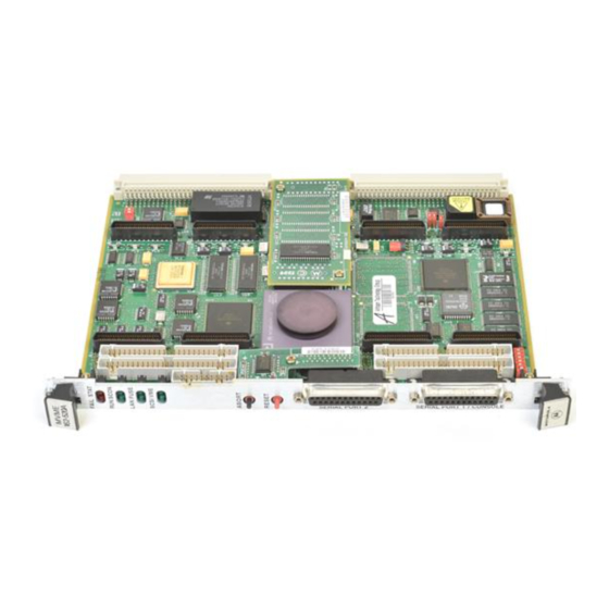
Summary of Contents for Motorola MVME162FX400 Series
- Page 1 MVME162FX 400/500-Series VME Embedded Controller Installation and Use V162FXA/IH4 Edition of March 2000...
- Page 2 While reasonable efforts have been made to assure the accuracy of this document, Motorola, Inc. assumes no liability resulting from any omissions in this document, or from the use of the information obtained therein. Motorola reserves the right to revise this document and to make changes from time to time in the content hereof without obligation of Motorola to notify any person of such revision or changes.
- Page 3 Preface MVME162FX 400/500-Series VME Embedded Controller Installation and Use provides instructions for hardware preparation and installation; a board-level hardware overview; and firmware-related general information and startup instructions for the 400/500-Series MVME162FX embedded controller. The board is referred to as the “MVME162FX” throughout this document.
- Page 4 Conventions Used in This Manual The following typographical conventions are used in this document: bold Is used for user input that you type just as it appears; it is also used for commands, options and arguments to commands, and names of programs, directories and files. italic Is used for names of variables to which you assign values.
- Page 5 (high or low) that they represent. ® Motorola and the Motorola logo are registered trademarks of Motorola, Inc. MC68040™ is a trademark of Motorola, Inc. IndustryPack™ and IP™ are trademarks of GreenSpring Computers, Inc. All other products mentioned in this document are trademarks or registered trademarks of their respective holders.
- Page 6 The safety precautions listed below represent warnings of certain dangers of which Motorola is aware. You, as the user of the product, should follow these warnings and all other safety precautions necessary for the safe operation of the equipment in your operating environment.
- Page 7 Flammability All Motorola PWBs (printed wiring boards) are manufactured with a flammability rating of 94V-0 by UL-recognized manufacturers. EMI Caution This equipment generates, uses and can radiate electromagnetic energy. It may cause or be susceptible to electromagnetic interference (EMI) if not installed and used CAUTION with adequate EMI protection.
- Page 8 CE Notice (European Community) Motorola Computer Group products with the CE marking comply with the EMC Directive (89/336/EEC). Compliance with this directive implies conformity to the following European Norms: EN55022 “Limits and Methods of Measurement of Radio Interference Characteristics of Information Technology Equipment”; this product tested to Equipment Class B EN50082-1:1997 “Electromagnetic Compatibility—Generic Immunity Standard,...
- Page 9 Contents CHAPTER 1 Hardware Preparation and Installation Introduction........................1-1 Getting Started ......................1-1 Overview of Installation Procedure ..............1-1 Equipment Required ...................1-2 Guidelines for Unpacking ...................1-2 ESD Precautions ....................1-3 Preparing the Board ....................1-4 Base Board Configurations.................1-5 VME System Controller Selection ..............1-8 SIM Selection for Serial Port B .................1-9 Removal of Existing SIM ................1-10 Installation of New SIM ................1-11 Serial Port 1/Console Clock................1-11...
- Page 10 Autoboot ......................2-9 ROMboot......................2-11 Network Boot ....................2-12 Restarting the System ....................2-12 Reset ......................... 2-13 Abort......................... 2-14 Break ........................ 2-14 Diagnostic Facilities ....................2-14 CHAPTER 3 162Bug Firmware Introduction ....................... 3-1 162Bug Overview...................... 3-1 162Bug Implementation .................... 3-3 Memory Requirements ..................
- Page 11 Battery-Backed-Up RAM and Clock..............4-12 VMEbus Interface and VMEchip2 ..............4-12 I/O Interfaces ....................4-13 Serial Communications Interface ..............4-13 IndustryPack (IP) Interfaces ..............4-17 Ethernet Interface ..................4-17 SCSI Interface....................4-18 SCSI Termination ..................4-19 Local Resources....................4-19 Programmable Tick Timers ...............4-19 Watchdog Timer ..................4-19 Software-Programmable Hardware Interrupts...........4-20 Local Bus Timeout ..................4-20 Local Bus Arbiter....................4-21 Connectors ......................4-21...
- Page 12 APPENDIX C Network Controller Data Network Controller Modules Supported ..............C-1 APPENDIX D Disk/Tape Controller Data Controller Modules Supported ................. D-1 Default Configurations ..................... D-2 IOT Command Parameters ..................D-5 APPENDIX E Related Documentation MCG Documents .......................E-1 Manufacturers’ Documents ..................E-2 Related Specifications ....................E-3...
- Page 13 List of Figures Figure 1-1. MVME162FX Layout (01-W3960Bxxx Base Board) ......1-6 Figure 1-2. MVME162FX Layout (01-W3182Fxxx Base Board) ......1-7 Figure 1-3. Serial Interface Module, Connector Side ..........1-9 Figure 1-4. EIA-232-D Connections to MVME712M (Sheet 1 of 6)......1-25 Figure 1-5. EIA-530 Connections (Sheet 1 of 2) .............1-31 Figure 1-6.
- Page 15 Table 5-8. VMEbus Connector P1 Pin Assignments ..........5-10 Table 5-9. VMEbus Connector P2 Pin Assignment..........5-11 Table A-1. MVME162FX Specifications ..............A-1 Table B-1. Troubleshooting MVME162FX Boards ..........B-1 Table E-1. Motorola Computer Group Documents ..........E-1 Table E-2. Manufacturers’ Documents ..............E-2 Table E-3. Related Specifications ................E-3...
- Page 17 1Hardware Preparation and Installation Introduction This chapter provides unpacking instructions, hardware preparation guidelines, and installation instructions for the MVME162FX VME Embedded Controller. Hardware preparation of the MVME712 series transition modules compatible with this board is covered in separate manuals. Getting Started This section supplies an overview of startup procedures applicable to the MVME162FX.
- Page 18 Hardware Preparation and Installation Table 1-1. Startup Overview (Continued) What you need to do... Refer to... Connect any other equipment you Connector Pin Assignments in Chapter 5. will be using. For more information on optional devices and equipment, refer to the documentation provided with the equipment. Power up the system.
- Page 19 This section applies to all hardware installations you may perform that involve the MVME162FX board. Motorola strongly recommends the use of an antistatic wrist strap and a conductive foam pad when you install or upgrade the board. Electronic components can be extremely sensitive to ESD. After removing the board from the chassis or from its protective wrapper, place the board flat on a grounded, static-free surface, component side up.
- Page 20 Hardware Preparation and Installation Turn the system’s power off before you perform these procedures. Failure to turn the power off before opening the Warning enclosure can result in personal injury or damage to the equipment. Hazardous voltage, current, and energy levels are present in the chassis.


