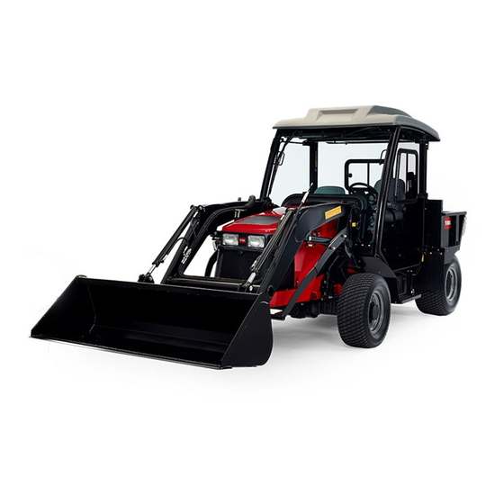
Toro Outcross 9060 Series Installation Instructions Manual
Road light and horn kit traction unit
Hide thumbs
Also See for Outcross 9060 Series:
- Operator's manual (88 pages) ,
- Installation instructions manual (24 pages)
Table of Contents
Advertisement
Quick Links
Road Light and Horn Kit
Outcross 9060 Series Traction Unit
Model No. 07542
Installation
Loose Parts
Use the chart below to verify that all parts have been shipped.
Procedure
1
2
3
4
5
6
7
8
9
10
© 2019-The Toro® Company
8111 Lyndale Avenue South
Bloomington, MN 55420
Description
No parts required
No parts required
Tail light assembly bracket
Horn-switch assembly (switch and jam
nut)
15A fuse
10A fuse
Register at www.Toro.com.
Form No. 3429-379 Rev B
Installation Instructions
Qty.
-
Prepare the machine.
-
Remove the roof panel.
4
2
Install the rear lights.
2
4
6
6
2
1
Install the front lights.
1
1
1
1
Install the horn.
1
2
2
1
Install the sign.
3
3
3
1
Install the horn switch.
1
1
Install the flasher switch.
1
4
4
Install the dual flasher.
1
1
1
Install the fuses.
1
Original Instructions (EN)
All Rights Reserved *3429-379* B
Printed in the USA
Use
Advertisement
Table of Contents

Related Manuals for Toro Outcross 9060 Series


Summary of Contents for Toro Outcross 9060 Series
-
Page 1: Table Of Contents
Form No. 3429-379 Rev B Road Light and Horn Kit Outcross 9060 Series Traction Unit Model No. 07542 Installation Instructions Installation Loose Parts Use the chart below to verify that all parts have been shipped. Procedure Description Qty. – No parts required Prepare the machine. - Page 2 Procedure Description Qty. Yellow reflective tape Install the reflective tape. Red reflective tape – No parts required Install the roof panel. Preparing the Machine Removing the Roof Panel No Parts Required No Parts Required Procedure Procedure Park the machine on a level surface, move the Remove the 6 flange-head bolts and 6 washers shift lever to the N position, and lower...
-
Page 3: Nut (5/16 Inch)
Installing the Rear Lights Parts needed for this procedure: Nut (5/16 inch) Tail light assembly Tail light assembly bracket Hex-head bolt (5/16-18 x 1 inch) Procedure Secure the tail light assemblies to the tail light assembly brackets (Figure Note: Ensure that the yellow lens is on the top of the bracket. g274525 Figure 2... - Page 4 Remove the bolts and nuts on the left side of the machine as shown in Box A of Figure Note: Remove hardware from one side at a time. g264165 Figure 3 Secure the tail light assembly and bracket to each side of the machine using 4 bolts (5/16-18 x 1 inch) and 4 nuts (5/16 inch).
-
Page 5: Bolt (1/4-20 X 3/4 Inch)
Installing the Front Lights Parts needed for this procedure: Bolt (1/4-20 x 3/4 inch) Locknut (1/4 inch) Front light assembly Right front light bracket Left front light bracket Wire harness Push-mount fastener Procedure Determine the left and right position based on the normal operating position. Attach the front list assembly to the front light bracket (Box A of... - Page 6 Note: Coil the excess harness up under the roof when the license plate light kit is not used. Secure the harness using the push mount fastener and cable tie to the roof rail (Figure Insert the push mount fasteners in the holes on the frame (Figure g274364 Figure 5...
-
Page 7: Horn
Installing the Horn Parts needed for this procedure: Horn Attaching the Horn to the Machine g254486 Figure 6 At the frame of the machine below the right-front engine bracket, remove the flange locknut (5/16 inch) from the bolt (5/16 x 2-3/4 inches) that secures the coolant-reservoir bracket to the frame (Figure g254490 Figure 7... - Page 8 g254491 Figure 8 1. Bolt (frame/bracket 5/16 x 2-3/4 inches) 3. Flange locknut (5/16 inch) 2. Bracket (horn) Connecting the Wire Harness to the Horn Connect the terminal receptacles for the yellow and black wires onto the blade terminals of the horn (Figure Note: You can connect either wire to either blade terminal of the horn.
-
Page 9: Bracket
Installing the Slow Moving Vehicle Sign Parts needed for this procedure: Bracket Bolt (5/16-18 x 3 inches) Nut (5/16 inch) Slow moving vehicle sign Hex bolt (1/4-20 x 3/4 inch) g284933 Flat washer Figure 11 Nut (1/4 inch) Procedure Install the slow moving vehicle sign using 3 bolts (1/4-20 x 3/4 inch), 3 washers, and 3 nuts (1/4 inch) as shown in Figure... -
Page 10: Horn-Switch Assembly
Installing the Horn Switch Remove the plug from the steering column-panel (Figure 14). Installing the Horn Switch Parts needed for this procedure: Horn-switch assembly (switch and jam nut) Rubber button Removing the Steering-Column Panel Remove the 4 socket-head screws that secure the steering column-panel to the dash (Figure 12). -
Page 11: Paddle Switch
g272242 Figure 15 1. Blade connector (switch) 2. 2-socket connector ( HORN SWITCH Installing the Flasher Switch Parts needed for this procedure: Paddle switch Procedure Install the paddle switch and connect it to the kit wire harness (Figure 16). g278146 Figure 16 Install the steering-column panel. -
Page 12: Bracket
Installing the Dual Flasher Parts needed for this procedure: Bracket Clip nuts Bolts (#10 x 1/2 inch) Dual flasher Wire harness Installing the Flasher Remove the 3 bolts and rotate the control panel out to the right (Box A of Figure 17). - Page 13 Install the bracket and relay using the 2 bolts previously removed (Figure 18). Install 4 clipnuts onto the bracket (Figure 18). g274359 Figure 18 Install the dual flasher onto the bracket using 4 bolts (#10 x 1/2 inch) (Box A of Figure 19).
- Page 14 Installing the Fuses Parts needed for this procedure: 15A fuse 10A fuse Procedure Install the 15A fuse into the fuse block slot at column B, row 4. g274357 Figure 20 Install the 10A fuse into the fuse block slot at column C, row 4.
- Page 15 Operation Controls Installing the Roof Panel No Parts Required Procedure Lift the roof panel and align the holes on the panel with the clip nuts in the roof-mount channel. Assemble the panel to the roof mount with the 6 flange-head bolts and 6 washers (Figure that you removed in 2 Removing the Roof Panel...