
Subscribe to Our Youtube Channel
Related Manuals for corob CLEVERmix 700


Summary of Contents for corob CLEVERmix 700
- Page 1 TECHNICAL MANUAL COROB™ CLEVERmix 700 Gyroscopic Mixer with MINIEMIX Electronics TM - V1.0R0 (05/2017) CODE - EVD...
- Page 2 COROB™ is a registered trademark and/or commercial trademark used on an exclusive basis by COROB S.p.A. and its affiliated companies (hereinafter “COROB”). A failure of a trademark to appear hereunder does not mean that COROB does not use the trademark in question nor does it constitute a waiver by COROB of any related intellectual property rights.
-
Page 3: Table Of Contents
Mixing speed limits (MANUAL) ............................... 42 5.2.12 Mixing time limits (MANUAL) ................................. 42 5.2.13 Clamping plate re-opening ................................42 5.2.14 Restore configuration ..................................43 5.2.15 Factory reset ....................................... 43 HARDWARE ERRORS .................................. 47 Introduction ..........................................47 Errors and warning messages ....................................47 COROB™ CLEVERmix 700... - Page 4 Door safety device ........................................62 7.10.1 Disassembly / Assembly / Replacement ............................62 7.11 Inverter ............................................63 7.11.1 Disassembly / Assembly / Replacement ............................63 7.12 Power Supply Unit ........................................64 7.12.1 Disassembly / Assembly / Replacement ............................64 Appendix: Electrical Technical File COROB™ CLEVERmix 700...
- Page 6 BLANK PAGE COROB™ CLEVERmix 700...
-
Page 7: General Information And Safety
IMPORTANT NOTE At the time of publishing this edition of the manual COROB has used its best efforts to ensure that the information contained herein is complete and accurate. Notwithstanding, pursuant to product development and technical innovation over time, COROB may have introduced changes and/or revisions to COROB™... -
Page 8: Symbols
It is forbidden to use the machine as a working surface; it is also prohibited to leave objects on the machine during while it’ is operating. • Always unplug the power supply cable from the socket outlet before carrying out any maintenance operations. COROB™ CLEVERmix 700... - Page 9 The substances that may be used on the machine--such as colorants, paints, solvents, lubricants and cleansers--may be hazardous to your health; handle, store and dispose of these substances in keeping with current regulations and the instructions provided with the product. COROB™ CLEVERmix 700...
-
Page 10: Residual Risks
As a preventive measure, ALWAYS wait at least 30 minutes after the last working cycle has ended, before touching the mixing motor to carry out maintenance interventions. The motor is protected by a safety guard and cannot be reached by the machine operator normally. COROB™ CLEVERmix 700... -
Page 11: Safety Devices
As an optional device, a door lock system can be requested: it prevents door opening at any time of the cycle. With this option, it will not be possible to open the door, neither during plate closing (clamping of the can) nor during plate opening (release of the can). COROB™ CLEVERmix 700... -
Page 12: Emergency Stop
The use of the emergency stop button is to be considered as an emergency action exclusively, and not as a standard stop mode, in order to prevent machine deterioration. Tools List of suggested tools required to operate with COROB™ equipment. Description Type... - Page 14 BLANK PAGE COROB™ CLEVERmix 700...
-
Page 15: Information And Technical Features
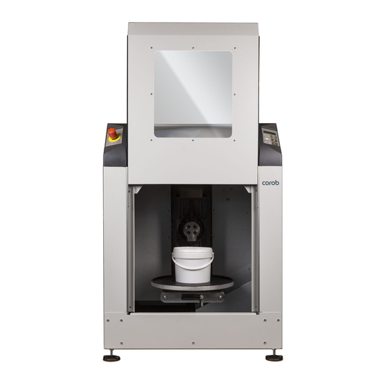
INFORMATION AND TECHNICAL FEATURES Description of the machine The gyroscopic mixer COROB™ CLEVERmix 700 with automatic clamping system allows mixing of non-explosive paints contained into metal or plastic containers. It is suitable to handle cans of different size and shape. With specially profiled clamping plates available for installation upon request, the machine can also handle square cans. -
Page 16: Performance And Features
Environment working conditions Relative humidity: between 5% and 85%, without condensation (*) Value measured in laboratory and documented by the corresponding test report available at the manufacturer’s. Operating conditions: machine normal working cycle, under simulated load conditions. COROB™ CLEVERmix 700... -
Page 17: Dimensions And Weight
INFORMATION AND TECHNICAL FEATURES - 17 Dimensions and weight 805 mm - 31,7” 163 kg 188 kg 360 lb 415 lb Adjusting height of the antivibration feet from 0” to 0.79” (0 to 25 mm). COROB™ CLEVERmix 700... - Page 18 BLANK PAGE COROB™ CLEVERmix 700...
- Page 20 BLANK PAGE COROB™ CLEVERmix 700...
-
Page 21: Installation
Unpack and position the machine as described in the user’s manual present on the machine. 1 x 19 mm To remove the mounting screws 1 x 10 mm To adjust the support feet 1 x 19 mm COROB™ CLEVERmix 700... - Page 22 22 - INSTALLATION 10 mm 19 mm 10 mm 19 mm WARNING The machine must be perfectly level in order to operate properly and prevent from vibrating during the mixing cycle. COROB™ CLEVERmix 700...
-
Page 23: Electrical Connection And Start-Up
Information is displayed in automatic sequence. To scroll through the single pieces of information manually, use the ( ) and ( ) keys on the control panel. – By pressing the ( ) and ( ) keys also the last detected machine errors are shown. Symbol (!) indicates planned maintenance to be carried out. COROB™ CLEVERmix 700... - Page 24 BLANK PAGE COROB™ CLEVERmix 700...
- Page 26 BLANK PAGE COROB™ CLEVERmix 700...
-
Page 27: Control Electronics
CONTROL ELECTRONICS - 27 CONTROL ELECTRONICS Introduction COROB™ MINIEMIX control electronics improves machine performance and facilitates service operations. COROB™ CLEVERmix 700 can be controlled and configured using the program CorobMIX, which allows to: • load the project file from the machine •... -
Page 28: Power Supply Voltage Distribution
100V 200V ÷ 110V 240V 127V Power Auto Socket Transformer Power supply unit Inverter Mixing motor MiniEmix keyboard MiniEmix board Clamping motor Emergency panel Door safety device Position Repositioning Door safety sensors pin motor device pin COROB™ CLEVERmix 700... -
Page 29: Miniemix Board Layout
J8 MECHANICS ENCODER ZERO POSITION J6A INVERTER SENSOR INPUT J9 REP. PIN “OUT” J6 MAX OPEN SENSOR PLATE and BOTTOM PLATE IN J21 [not used] SENSOR J5 INVERTER OUTPUT J4 DOOR CONTACT POWER POWER J3 EMERGENCY CONTACT COROB™ CLEVERmix 700... -
Page 30: Connectors
INPUT / USB CONNECTOR OUTPUT OUTPUT CONTACTOR SELECTOR J13A OUTPUT CONTACTOR OUTPUT NOT USED J14A OUTPUT REPOSITIONING PIN MOTOR JTAG PROGRAMMER [RESERVED] ENCODER SENSOR NOT USED OUTPUT DOOR LOCK NOT USED ESPANSION (NOT USED) ANALOG INPUT (NOT USED) COROB™ CLEVERmix 700... -
Page 31: Leds
Inverter / Plate max open sensor / Re. J6 - J6A DS10 ON [green] Vertical repositioning pin / Re. J7 DS11 ON [green] Mechanics zero pos. sensor / Re. J8 DS12 ON [green] Vertical repositioning pin / Re. J9 DS13 [not used] Re. J21 [not used] COROB™ CLEVERmix 700... -
Page 32: Dipswitch Settings
ON: SKIP CYCLE PHASES (IF THIS OPTION IS ACTIVE IN THE COROBMIX CONFIGURATION) MACHINE MODEL SELECTION [DEFAULT: OFF] MACHINE MODEL SELECTION [DEFAULT: OFF] MACHINE MODEL SELECTION [DEFAULT: OFF] MACHINE ENCODER PRESENCE (OFF: encoder present) (ON: encoder not present) COROB™ CLEVERmix 700... - Page 34 BLANK PAGE COROB™ CLEVERmix 700...
-
Page 35: Control Panel And Configuration
This key allows to access manual edit mode for the following mixing parameters: • mixing time (from 00:45 to 09:45 min) MODE clamping force (from 150 to 300 kg) • mixing speed (from 50 to 200 rpm) • • mixing type ( / / / ) COROB™ CLEVERmix 700... -
Page 36: Machine Parameters Configuration
Mixing Time Limits in manual mode chapter 5.2.12 Partial plate opening [only when machine is equipped with Encoder] chapter 5.2.13 Furthermore it is also possible to: • Restore machine configuration (chapter 5.2.14) • Reset machine to factory configuration (chapter 5.2.15) COROB™ CLEVERmix 700... -
Page 37: Parameter Grid
<- Max. Force -> <- Max. Speed -> <-Manual Time-> PRESS SIMULTANEOUSLY TO EXIT [Save Changes] [Factory Reset] [Restore Config] <-Exit Config?-> <-Exit Config?-> <-Exit Config?-> PRESS SIMULTANEOUSLY TO SELECT Save Changes Factory Reset Restore Config PRESS SIMULTANEOUSLY TO CONFIRM COROB™ CLEVERmix 700... -
Page 38: Control Panel Keys
The code 00 indicates a custom language that has been downloaded using CorobMIX. Language change via the control keyboard has immediate effect and does not need machine re-initialization. Only when you do not confirm parameter change at the end of the configuration procedure, the default language is restored. COROB™ CLEVERmix 700... -
Page 39: Editing Parameters
At the end of the procedure, the machine will execute a RESTART MACHINE process. This is a board hardware reset process, where the machine is turned automatically OFF and back ON in a fast sequence. Bring the machine back to normal working conditions by releasing the emergency button. COROB™ CLEVERmix 700... -
Page 40: Mixing Speed (Auto)
“Min. Speed” parameter (see ch. 5.2.8). 00:45] <100mm ¤ • The machine will use the MinTime set, for all the cans height values lower than the value in <-Mixing Time-> “Max. Speed” parameter (see ch. 5.2.8). 05:00] >300mm ¤ <-Mixing Time-> COROB™ CLEVERmix 700... -
Page 41: Clamping Force Adjustment (Auto)
<- Max. Force -> NOTE: Min Manual Force and Max Manual Force define the limit of the clamping force in manual mode. Min Auto Force and Max Auto Force are used when force is defined by can height. COROB™ CLEVERmix 700... -
Page 42: Mixing Speed Limits (Manual)
When a cycle is stopped with one of the group of cycles keys, the configured partial re-opening is done (this can be useful in a machine configuration where you want to execute partial re-opening, but no dedicated “plate open” key is present). COROB™ CLEVERmix 700... -
Page 43: Restore Configuration
This option restores the default machine configuration that was loaded at machine factory-production. This configuration was loaded with CorobMIX program and with dipswitch 7 = ON on MINIEMIX board and can in any time be recovered to check basic machine functions if the customer configuration is lost. COROB™ CLEVERmix 700... - Page 44 BLANK PAGE COROB™ CLEVERmix 700...
- Page 46 BLANK PAGE COROB™ CLEVERmix 700...
-
Page 47: Hardware Errors
HARDWARE ERRORS Introduction The COROB™ CLEVERmix 700 MINIEMIX Electronics manages the display of messages relating to actions performed by the machine during the mixing cycle, as well as alarms that refer to machine error conditions or faults. Messages and error codes are displayed on the 16-chrs LCD display. - Page 48 0012 CLAMP MOTOR ERR Generic alarm on the clamping motor. Check correct adjustment or operation of the sensor. Check correct operation of the clamping motor. Check contactor selector J13. Check inverter status or errors during motor operation. COROB™ CLEVERmix 700...
- Page 49 Check clamping mechanics vertical position sensor (J8). DOOR MOV. FAULT 0026 The door closed sensor (J4) detects the door Check J4 sensor. open during mixing cycle. COROB™ CLEVERmix 700...
- Page 50 BLANK PAGE COROB™ CLEVERmix 700...
- Page 52 BLANK PAGE COROB™ CLEVERmix 700...
-
Page 53: Maintenance
Check and clean the guides of the pull-out bottom plate (chapter 7.3) Clean and lubricate the upper and lower clamping screws (chapter 7.3) Lubricate the mixing mechanics stop pin and roller (chapter 7.3) Check correct tension of mixing motor drive belt (chapter 7.6.2) COROB™ CLEVERmix 700... -
Page 54: Lubrication Points
Carry out one or more mixing cycles to allow the clamping plates to close and then open so to evenly spread the lubricant. Start a mixing cycle and press the emergency button. Open the door and lubricate the roller. COROB™ CLEVERmix 700... -
Page 55: Guards And Panels Disassembly
Remove the 2 x SCREWS M5x12 present on the sides of the upper side of the REAR PANEL. Loosen the remaining 7 x SCREWS M5x12 (do not take them off ) and remove the REAR PANEL. Remove UPPER COVER. Do not remove the screws completely. Remove the front bottom panel (5 screws). COROB™ CLEVERmix 700... -
Page 56: Door
Open and close door multiple times to spread the lubricant until the door runs smoothly. 7.5.2 Disassembly and reassembly Remove the front bottom panel (previous chapter). Withdraw the shutter door from below. To re-assemble the door, proceed in reverse order. COROB™ CLEVERmix 700... -
Page 57: Mixing Motor
Install new belt centrally on the pulley (leave 3 grooves on both sides of the belt). Adjust belt tension, by tightening or loosing screw B. When correct tension is reached, tighten the four screws A. COROB™ CLEVERmix 700... -
Page 58: Clamping Motor
Disconnect sensors A and repositioning pin motor B. Remove the four screws C that hold the motor plate. Disconnect only the wires from the contactor. The clamping motor group is now free to be removed from the machine and put on a work bench. COROB™ CLEVERmix 700... - Page 59 MAINTENANCE - 59 Remove two screws A. Remove shaft B and C. Remove door lock lever D and the spring E. When reassembling the new clamping motor, use a plastic camp. COROB™ CLEVERmix 700...
-
Page 60: Repositioning Pin Motor
Take off the motor C and cam D from its support. Remove the two screws and take off the back cover E, with the wiring. Install the new motor proceeding in reverse order. Pay special care to correctly mount the cam in the right vertical position. COROB™ CLEVERmix 700... -
Page 61: Sensors
After replacement, remember to adjust the new sensor position (fom reading reference: min. distance 1 mm - max. distance 3 mm). The proximity sensor 3 must be centered with the head of the reading reference screw on the pulley (distance: 1 mm) COROB™ CLEVERmix 700... -
Page 62: 7.10 Door Safety Device
(see last picture). If it is necessary to adjust the door lock lever, proceed as shown in figure below (C) by loosing the screws and sliding back and forth the lever end part. COROB™ CLEVERmix 700... -
Page 63: 7.11 Inverter
Remove screw C, and take off the inverter. Install the new inverter. Reconnect all cables and ground connections as originally. Proceed with inverter programming with machine-specific settings (contact COROB SPA Italy). yellow = ground relay-cable (black - grey - brown) -
Page 64: 7.12 Power Supply Unit
Disassembly / Assembly / Replacement Disconnect power supply unit cables 1. Remove screw A, and the bottom screw B that hold the power supply unit to the plate. Install the new power supply unit. Reconnect all cables as originally. COROB™ CLEVERmix 700... - Page 65 TECHNICAL FILE CLEVERmix 700 Gyroscopic mixer COROB™ CLEVERmix 700 CE version 10000018386AA...
- Page 66 COROB™ is a registered trademark and/or commercial trademark used on an exclusive basis by COROB S.p.A. and its affiliated companies (hereinafter “COROB”). A failure of a trademark to appear hereunder does not mean that COROB does not use the trademark in question nor does it constitute a waiver by COROB of any related intellectual property rights.
- Page 67 2 – M ECTION IXER CMX700 power control panel assembly 200-240Vac or (*)100-127Vac ................9 3 – C ECTION OMPONENT PECIFICATION CLEVERmix 700 PR Inverter Toshiba VF-nC3 parameter ....................11 MINIEMIX_C connector lay-out ............................12 NONE COROB™ CLEVERmix 700 CE version 10000018386AA...
- Page 68 SECTION COROB™ CLEVERmix 700 CE version 10000018386AA...
- Page 69 Fabrizio Benatti Friday, May 05, 2017 Friday, May 05, 2017 Friday, May 05, 2017 property of COROB S.p.A. property of COROB S.p.A. property of COROB S.p.A. You may not copy or distribute any You may not copy or distribute any...
- Page 70 Fabrizio Benatti Friday, May 05, 2017 Friday, May 05, 2017 Friday, May 05, 2017 property of COROB S.p.A. property of COROB S.p.A. property of COROB S.p.A. You may not copy or distribute any You may not copy or distribute any...
- Page 71 Via Agricoltura 103 · 41038 San Felice s/P · Modena · Italy Phone: + 39-0535-6633 · Fax: + 39-0535-663400 Power Circuit - CMX700 - CE configuration (std 200-240V, option 100,110,127V) CLEVERmix 700 10000018386 rev.AA Revised: May 2017 Bill Of Materials...
- Page 72 SECTION COROB™ CLEVERmix 700 CE version 10000018386AA...
- Page 73 10000018386 a u t h o r i z a t i o n C o r o b S . P. A . DESCRIPTION COROB CODE None CMX700 power control panel assembly - CE ver. 200-240Vac or 100-127Vac...
- Page 74 SECTION COROB™ CLEVERmix 700 CE version 10000018386AA...
- Page 75 To initialize the inverter to the “Toshiba factory default settings”, set the “tYP” parameter to “13”. When “13” is set, “InIt” is displayed for a short time and then disappears. At this point, the situation is the same as described at the previous note. COROB™ CLEVERmix 700 CE version 10000018386AA...
- Page 76 Door lock J14A J13A Pin Motor Contactor COROB MiniEMIX C. Keyboard Pin IN Max open Plate Zero Position Inverter IN Pin OUT Inverter OUT Power IN Door contact Power OUT Emergency contact ITEM CPS CODE DRAWING NO. DESCRIPTION DESIGNER DATE...
Need help?
Do you have a question about the CLEVERmix 700 and is the answer not in the manual?
Questions and answers
I Have a clevermix 700 and it does not squeeze the gallon anymore it stays open at around 11 inches is it a matter of programing?
No. The Corob CLEVERmix 700 not squeezing the gallon properly is likely due to a mechanical issue, such as a can that is too small, a fault in the clamping motor or plate position sensors, or a fault with the J6A sensor cable and inverter output—not a programming issue.
This answer is automatically generated