
Related Manuals for Advantech EKI-7712G-4FMPI


Summary of Contents for Advantech EKI-7712G-4FMPI
- Page 1 User Manual EKI-7712G-4FMPI 8GE + 4G SFP Port Managed Redundant High PoE Industrial Switch...
- Page 2 No part of this manual may be reproduced, copied, translated or transmitted in any form or by any means without the prior written permission of Advantech Co., Ltd. Information provided in this manual is intended to be accurate and reliable. How- ever, Advantech Co., Ltd.
- Page 3 Technical Support and Assistance Visit the Advantech web site at www.advantech.com/support where you can find the latest information about the product. Contact your distributor, sales representative, or Advantech's customer service center for technical support if you need additional assistance.
- Page 4 Before setting up the system, check that the items listed below are included and in good condition. If any item does not accord with the table, please contact your dealer immediately. 1 x Industrial Ethernet Switch 1 x DIN-Rail mounting Bracket and Screws 1 x Wall-mounting Bracket EKI-7712G-4FMPI User Manual...
- Page 5 The sound pressure level at the operator's position according to IEC 704-1:1982 is no more than 70 dB (A). DISCLAIMER: This set of instructions is given according to IEC 704-1. Advantech disclaims all responsibility for the accuracy of any statements contained herein.
- Page 6 Der arbeitsplatzbezogene Schalldruckpegel nach DIN 45 635 Teil 1000 beträgt 70dB(A) oder weiger. Haftungsausschluss: Die Bedienungsanleitungen wurden entsprechend der IEC- 704-1 erstellt. Advantech lehnt jegliche Verantwortung für die Richtigkeit der in die- sem Zusammenhang getätigten Aussagen ab. EKI-7712G-4FMPI User Manual...
- Page 7 Always disconnect the power from the device before servicing it. Before plugging a cable into any port, discharge the voltage stored on the cable by touching the electrical contacts to the ground surface. EKI-7712G-4FMPI User Manual...
-
Page 8: Table Of Contents
Accessing the CLI ............... 26 Web Browser Configuration ..............27 3.3.1 Preparing for Web Configuration ..........27 3.3.2 System Login ................27 Chapter Managing Switch .......28 Log In ...................... 29 Recommended Practices ................ 29 4.2.1 Changing Default Password ............29 EKI-7712G-4FMPI User Manual viii... - Page 9 Rate Limit.................. 100 4.8.4 Bandwidth Guarantee ............... 103 Management ..................104 4.9.1 LLDP ..................104 4.9.2 SNMP..................108 4.9.3 Power Over Ethernet ..............111 4.9.4 TCP Modbus Settings ............... 113 4.9.5 DHCP Server ................114 4.9.6 SMTP Client................119 EKI-7712G-4FMPI User Manual...
- Page 10 4.11.5 Save Configuration ..............136 4.11.6 User Account ................136 4.11.7 N-Key..................136 4.11.8 Reset System ................137 4.11.9 Reboot Device ................137 4.12 Modbus/TCP Mapping ................137 4.12.1 Modbus/TCP Mapping Table ............ 138 Chapter Troubleshooting......153 Troubleshooting ..................154 EKI-7712G-4FMPI User Manual...
- Page 11 L2 Switching > 802.1Q VLAN > Port to VLAN............. 51 Figure 4.28 L2 Switching > 802.1Q VLAN > Port-VLAN Mapping..........52 Figure 4.29 L2 Switching > Q-in-Q > Global Settings..............52 Figure 4.30 L2 Switching > Q-in-Q > Port Settings................. 53 EKI-7712G-4FMPI User Manual...
- Page 12 Security > 802.1x > 802.1x Port Configuration............84 Figure 4.87 Security > IP Security > Global Settings..............84 Figure 4.88 Security > IP Security > Entry Settings................ 85 Figure 4.89 Security > Security Login > Global Settings > Security Login Global Settings .... 85 EKI-7712G-4FMPI User Manual...
- Page 13 Management > Power Over Ethernet > PoE Port Settings ........112 Figure 4.146 PoE Information......................113 Figure 4.147 Management > Power Over Ethernet > PoE Port Status .......... 113 Figure 4.148 Management > TCP Modbus Settings > TCP Modbus Settings ....... 113 xiii EKI-7712G-4FMPI User Manual...
- Page 14 Figure 4.178 Tools > Backup Manager ..................134 Figure 4.179 Tools > Upgrade Manager..................135 Figure 4.180 Tools > Dual Image ....................135 Figure 4.181 Tools > User Account ....................136 Figure 4.182 Tools > N-Key ......................136 EKI-7712G-4FMPI User Manual...
-
Page 15: Chapter 1 Product Overview
Chapter Product Overview... -
Page 16: Specifications
EN 61000-4-2 EN 61000-4-3 EN 61000-4-4 EN 61000-4-5 EN 61000-4-6 EN 61000-4-8 EN 50121-4 CE, FCC Class A Shock IEC 60068-2-27 Freefall IEC 60068-2-32 Vibration IEC 60068-2-6 Traffic Control NEMA TS2 EKI-7712G-4FMPI User Manual... -
Page 17: Hardware Views
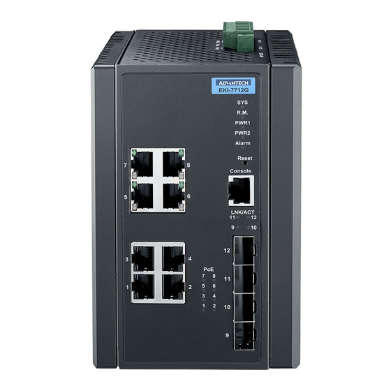
See “System LED Panel” on page 4 for further details. Reset button Button allows for system soft reset or factory default reset. Console serial port Console cable port to COM port (DB9 male) on computer to RS232 managed switch (RJ45). ETH port Fiber ports x 4 EKI-7712G-4FMPI User Manual... -
Page 18: Figure 1.2 System Led Panel
Powered down or not installed PWR2 Solid green Powered up Power down or not installed Alarm Solid red Defined major policies are detected Blinking Red Defined minor policies are detected Powered off or system is operating normally EKI-7712G-4FMPI User Manual... -
Page 19: Rear View
Rear View Figure 1.3 Rear View No. Item Description Wall mounting holes Screw holes (x6) used in the installation of a wall mounting plate DIN-Rail mounting Mounting plate used for the installation to a standard DIN rail plate EKI-7712G-4FMPI User Manual... -
Page 20: Top View
Terminal block Connect cabling for power and alarm wiring Dimensions 37.7 35.5 [1.485] [1.400] 82.5 [3.248] 97 [3.819] 114 [4.488] 47 [1.850] 105 [4.134] 35.1 40.6 [1.772] [0.965] 105 [4.134] 97 [3.819] [1.385] [1.600] 6-M3xP0.5 Figure 1.5 Dimensions EKI-7712G-4FMPI User Manual... -
Page 21: Chapter 2 Switch Installation
Chapter Switch Installation... -
Page 22: Installation Guidelines
35 mm (1.37”) x 75 mm (3”) height DIN rail. The devices can be mounted vertically or horizontally. Refer to the following guidelines for further infor- mation. Note! A corrosion-free mounting rail is advisable. When installing, make sure to allow for enough space to properly install the cabling. EKI-7712G-4FMPI User Manual... -
Page 23: Figure 2.1 Installing The Din-Rail Mounting Kit
Figure 2.2 Correctly Installed DIN Rail Kit Grasp the bottom of the switch and slightly rotate it upwards. If there is resis- tance, the switch is correctly installed. Otherwise, re-attempt the installation pro- cess from the beginning. EKI-7712G-4FMPI User Manual... -
Page 24: Wall-Mounting
Remove the DIN mounting plate. Store the DIN mounting plate and provided screws for later use. Align the wall mounting plates on the rear side. The screw holes on the device and the mounting plates must be aligned, see the following illustration. EKI-7712G-4FMPI User Manual... -
Page 25: Figure 2.4 Installing Wall Mount Plates
Do not completely tighten the screws into the wall. A final adjust- ment may be needed before fully securing the wall mounting plates on the wall. Align the wall mount plate over the screws on the wall. EKI-7712G-4FMPI User Manual... -
Page 26: Installing And Removing Sfp Modules
(A-to-A and B-to-B, as shown below, or A1-to-A2 and B1-to-B2). Note! This is a Class 1 Laser/LED product. To avoid causing serious damage to your eyes, do not stare directly into the Laser Beam. EKI-7712G-4FMPI User Manual... -
Page 27: Installing Sfp Modules
Remove the protective plug from the SFP transceiver. Note! Do not remove the dust plug from the transceiver if you are not installing the fiber optic cable at this time. The dust plug protects hardware from dust contamination. EKI-7712G-4FMPI User Manual... -
Page 28: Removing Sfp Modules
Hold the handle on the transceiver and pull the transceiver out of the slot. Handle Figure 2.11 Removing an SFP Transceiver Note! Replace the dust plug on the slot if you are not installing a transceiver. The dust plug protects hardware from dust contamination. EKI-7712G-4FMPI User Manual... -
Page 29: Connecting The Switch To Ethernet Ports
Pin 2 Pin 6 Pin 3 Pin 3 Pin 3 Pin 1 Pin 6 Pin 6 Pin 6 Pin 2 Figure 2.12 Ethernet Plug & Connector Pin Position Maximum cable length: 100 meters (328 ft.) for 10/100BaseT. EKI-7712G-4FMPI User Manual... -
Page 30: Connecting The Switch To Console Port
Figure 2.13 Serial Console Cable Figure 2.14 DB 9 Pin Position DB9 Connector RJ45 Connector 1 Orange/White 2 Orange 3 Green/White 4 Blue 5 Blue/White 6 Green 7 Brown/White 8 Brown RJ45 Female Male Figure 2.15 Pin Assignment EKI-7712G-4FMPI User Manual... -
Page 31: Power Supply Installation
Dual power inputs are supported and allow you to connect a backup power source. Single DC Power Redundant DC Power P2 P1 P2 P1 Chassis Chassis (pane) (pane) One DC Supply Dual DC Supplies Figure 2.16 Power Wiring EKI-7712G-4FMPI User Manual... -
Page 32: Considerations
Caution! Before connecting the device properly ground the device. Lack of a proper grounding setup may result in a safety risk and could be hazard- ous. Caution! Do not service equipment or cables during periods of lightning activity. EKI-7712G-4FMPI User Manual... -
Page 33: Wiring A Relay Contact
2.7.4 Wiring a Relay Contact The following section details the wiring of the relay output. The terminal block on the EKI-7712G-4FMPI is wired and then installed onto the terminal receptor located on the switch. V2+V2- V1+V1-... -
Page 34: Wiring The Power Inputs
Figure 2.20 Removing a Terminal Block Insert a small flat-bladed screwdriver in the V1+/V1- wire-clamp screws, and loosen the screws. Insert the negative/positive DC wires into the V+/V- terminals of PW1. If setting up power redundancy, connect PW2 in the same manner. EKI-7712G-4FMPI User Manual... -
Page 35: Reset Button
Reset Button Reset configuration to factory default: Press and hold Reset button for 5 seconds. System reboot: Press and hold Reset button for 2 seconds. Note! Do NOT power off the Ethernet switch when loading default settings. EKI-7712G-4FMPI User Manual... -
Page 36: Chapter 3 Configuration Utility
Chapter Configuration Utility... -
Page 37: First Time Setup
Secure Shell (SSH). An SNMP interface can be used to read/write many settings. Command Line Interface (CLI) can be used to read/write most settings. Initial setup must be done using an Ethernet connection (recommended) or the serial port. EKI-7712G-4FMPI User Manual... -
Page 38: Using The Graphical (Web) Interface
This can be an IP address or a Fully Qualified Domain Name (FQDN) such as “domainname.org”. NTP Server: The IP address or domain name of an NTP (Network Time Proto- col) server from which the switch may retrieve the current time at startup. EKI-7712G-4FMPI User Manual... -
Page 39: Configuring The Ethernet Ports
Otherwise, the switch will use the fixed Ethernet port and the correspond- ing settings for it. Note! When 100f is selected for the SFP of a gigabit combination port, the cor- responding fixed Ethernet jack will be disabled unless it is changed back to 1000F. EKI-7712G-4FMPI User Manual... -
Page 40: Command Line Interface Configuration
To connect by Ethernet, open a command prompt window and type: telnet <switchip> (where <switchip> is the IP address of the switch) At the login prompt, type “cli” for the username and “admin” for the password. The switch will respond with “Managed switch configuration CLI ready”. EKI-7712G-4FMPI User Manual... -
Page 41: Web Browser Configuration
In the browser’s address bar, type the switch’s default IP address (192.168.1.1). The login screen displays. Enter the user default name and password (admin / admin). Click OK on the login screen to log in. The main interface displays. EKI-7712G-4FMPI User Manual... -
Page 42: Chapter 4 Managing Switch
Chapter Managing Switch... -
Page 43: Log In
In the User Name field, enter admin for this account. It is not necessary to change the user name, however, a change in the default settings increases the security settings. In the Password field, type in the new password. Re-type the same password in the Retype Password field. EKI-7712G-4FMPI User Manual... -
Page 44: Monitoring
Location, MAC Address, Firmware version, and more, pertaining to the system. The information is for review only. To modify the device information, see the respective item within the user interface. To access this page, click Monitoring > Device Information. Figure 4.3 Monitoring > Device Information EKI-7712G-4FMPI User Manual... -
Page 45: Logging Message
Target Click the drop-down menu to select a target to store the log messages. Buffered: Store log messages in RAM. All log messages are cleared after system reboot. File: Store log messages in a file. EKI-7712G-4FMPI User Manual... -
Page 46: Port Monitoring
Click the drop-down menu to select a port and its captured statistical setting values. Clear Click Clear to clear the counter selections. The ensuing table for IF MIB Counters settings are informational only: ifInOctets, ifI- nUcastPkts, ifInNUcastPkts, ifInDiscards, ifOutOctets, ifOutUcastPkts, ifOutNUcast- Pkts, ifOutDiscards, ifInMulticastPkts, ifInBroadcastPkts, ifOutMulticastPkts and ifOutBroadcastPkts. EKI-7712G-4FMPI User Manual... -
Page 47: Link Aggregation
Click the drop-down menu to enable or disable the Interframe Gap (IFG) statistic. 4.3.4 Link Aggregation The Link Aggregation function provides LAG information for each trunk. It displays membership status, link state and membership type for each port. To access this page, click Monitoring > Link Aggregation. EKI-7712G-4FMPI User Manual... -
Page 48: Figure 4.7 Monitoring > Link Aggregation
The definitions are as follows: No PRD, not in periodic state; FstPRD, in fast periodic state; SlwPRD, in slow periodic state; PrdTX, periodic state. AtState Displays the actor state field of the LACP PDU. PnState. Displays the partner state field of the LACP PDU description. EKI-7712G-4FMPI User Manual... -
Page 49: Lldp Statistics
The ensuing table for LLDP Port Statistics settings are informational only: Port, TX Frames (Total), RX Frames (Total, Discarded and Errors), RX TLVs (Discarded and Unrecognized) and RX Ageouts (Total). 4.3.6 IGMP Statistics The IGMP Statistics function displays statistical package information for IP multicast- ing. EKI-7712G-4FMPI User Manual... -
Page 50: Mld Statistics
Query RX, Special Group & Source Query RX, Leave TX, Report TX, General Query TX, Special Group Query TX and Special Group & Source Query TX. 4.3.7 MLD Statistics The MLD Statistics function displays statistical package information for MLD mes- sage. EKI-7712G-4FMPI User Manual... -
Page 51: Figure 4.10 Monitoring > Mld Statistics
RX, Invalid RX, Other RX, Leave RX, Report RX, General Query RX, Special Group Query RX, Special Group & Source Query RX, Leave TX, Report TX, General Query TX, Special Group Query TX and Special Group & Source Query TX. EKI-7712G-4FMPI User Manual... -
Page 52: System
Click Apply to save the values and update the screen. The ensuing table for IP Address Information settings are informational only: DHCP State, Static IP Address, Static Subnet Mask, Static Gateway, Static DNS Server 1 and Static DNS Server 2. EKI-7712G-4FMPI User Manual... -
Page 53: Ipv6 Settings
You can select a switch-configured hostname or specify an ASCII test string for the remote ID. You can also configure an ASCII text string to override the circuit ID. EKI-7712G-4FMPI User Manual... -
Page 54: Dhcp Auto Provision
4.4.4 DHCP Auto Provision The DHCP Auto Provision feature allows you to load configurations using a server with DHCP options. Through the remote connection, the switch obtains information from a configuration file available through the TFTP server. EKI-7712G-4FMPI User Manual... -
Page 55: Management Vlan
The following table describes the items in the previous figure. Item Description Management VLAN Click the drop-down menu to select a defined VLAN. Apply Click Apply to save the values and update the screen. The ensuing table for Management VLAN State are informational only: Management VLAN. EKI-7712G-4FMPI User Manual... -
Page 56: System Time
Enter the offsetting variable in seconds to adjust for daylight saving Offset time. Recurring From Click the drop-down menu to designate the start date and time for daylight saving time. Recurring To Click the drop-down menu to designate the end date and time for daylight saving time. EKI-7712G-4FMPI User Manual... -
Page 57: Network Port
Apply Click Apply to save the values and update the screen. The ensuing table for Network Port Information are informational only: HTTP, HTTPS, TELNET and SSH. EKI-7712G-4FMPI User Manual... -
Page 58: L2 Switching
Click Apply to save the values and update the screen. The ensuing table for Port Status settings are informational only: Port, Edit (click to enter description), Enable State, Link Status, Speed, Duplex, FlowCtrl Config and FlowCtrl Status. EKI-7712G-4FMPI User Manual... -
Page 59: Port Mirror
4.5.3.1 Load Balance The Load Balancing page allows you to select between a MAC Address or IP/MAC Address algorithm for the even distribution of IP traffic across two or more links. EKI-7712G-4FMPI User Manual... -
Page 60: Figure 4.20 L2 Switching > Link Aggregation > Load Balance
Clear (click to load default settings). 4.5.3.3 LAG Port Settings The LAG Port Settings page allows you to enable or disable, set LAG status, speed and flow control functions. In this example we will configure a LAG between the following switches: EKI-7712G-4FMPI User Manual... -
Page 61: Figure 4.22 L2 Switching > Link Aggregation > Lag Port Settings
Link Aggregation Control Protocol (LACP) provides a method to control the bundling of several physical ports together to form a single logical channel. By configuring the LACP function, the switch can negotiate an automatic bundling of links by sending LACP packets to the peer device (also implementing LACP). EKI-7712G-4FMPI User Manual... -
Page 62: Q Vlan
VLAN ID is assigned dynamically by the AAA server. 4.5.4.1 VLAN Management The management of VLANs is available through the VLAN Settings page. Through this page you can add or delete VLAN listings and add a prefix name to an added entry. EKI-7712G-4FMPI User Manual... -
Page 63: Figure 4.25 L2 Switching > 802.1Q Vlan > Vlan Management
Click the drop-down menu to select a port and edit its settings: FE1- FE8, GE1-GE2, or Trunk1 - Trunk8. PVID Enter the VLAN ID you want assigned to untagged or priority tagged frames received on this port. The value ranges 1 to 4094. The default is 1. EKI-7712G-4FMPI User Manual... - Page 64 The ensuing table for Port VLAN Status settings are informational only: Port, Inter- face VLAN Mode, PVID, Accept Frame Type and Ingress Filtering. 4.5.4.3 Port to VLAN The Port to VLAN page allows you to add a port to a VLAN and select the related parameters. EKI-7712G-4FMPI User Manual...
-
Page 65: Figure 4.27 L2 Switching > 802.1Q Vlan > Port To Vlan
Click Apply to save the values and update the screen. Apply 4.5.4.4 Port-VLAN Mapping To access this page, click L2 Switching > 802.1Q VLAN > Port-VLAN Mapping. The ensuing table for Port-VLAN Mapping Table settings are informational only: Port, Mode, Administrative VLANs and Operational VLANs. EKI-7712G-4FMPI User Manual... -
Page 66: Q-In-Q
4.5.5.1 Global Settings The Global Settings page allows you to set the outer VLAN Ethertype setting. To access this page, click L2 Switching > Q-in-Q > Global Settings. Figure 4.29 L2 Switching > Q-in-Q > Global Settings EKI-7712G-4FMPI User Manual... -
Page 67: Garp
GARP The Generic Attribute Registration Protocol (GARP) is a local area network (LAN) protocol. The protocol defines procedures for the registration and de-registration of attributes (network identifiers or addresses) by end stations and switches with each other. EKI-7712G-4FMPI User Manual... -
Page 68: Figure 4.31 L2 Switching > Garp > Garp Settings
Registration Protocol or Generic VLAN Registration Protocol) protocol which facili- tates control of virtual local area networks (VLANs) within a larger network. To access this page, click L2 Switching > GARP > GVRP Settings. Figure 4.32 L2 Switching > GARP > GVRP Settings EKI-7712G-4FMPI User Manual... -
Page 69: Az Eee
To access this page, click L2 Switching > 802.3az EEE. Figure 4.34 L2 Switching > 802.3az EEE The following table describes the items in the previous figure. Item Description Port Select Enter the port to setup the EEE function. EKI-7712G-4FMPI User Manual... -
Page 70: Multicast
IGMP conversation between hosts and routers and maintain a map of which links need which IP multicast streams. Multicasts can be filtered from the links which do not need them in turn controlling which ports receive specific multicast traffic. IGMP Settings EKI-7712G-4FMPI User Manual... -
Page 71: Figure 4.36 L2 Switching > Multicast > Igmp Snooping > Igmp Settings
Enable: IGMP snooping v2 report suppression is enabled. Disable: IGMP snooping 2 report suppression is disabled. Figure 4.38 IGMP Snooping Table Item Description Entry No Displays the IGMP entry number. VLAN ID Displays the IGMP entry VLAN ID EKI-7712G-4FMPI User Manual... -
Page 72: Figure 4.39 L2 Switching > Multicast > Igmp Snooping > Igmp Querier
Select the querier version (V2 or V3) designated to the selected VLAN Click Apply to save the values and update the screen. Apply The ensuing table for IGMP Querier Status settings are informational only: VLAN ID, Querier State, Querier Status, Querier Version and Querier IP. IGMP Static Groups EKI-7712G-4FMPI User Manual... -
Page 73: Figure 4.40 L2 Switching > Multicast > Igmp Snooping > Igmp Static Groups
The MLD Snooping page allows you to select the snooping status (enable or dis- able), the version (v1 or v2) and the enabling/disabling of the report suppression for the MLD querier, which sends out periodic general MLD queries and are forwarded through all ports in the VLAN. MLD Settings EKI-7712G-4FMPI User Manual... -
Page 74: Figure 4.42 L2 Switching > Multicast > Mld Snooping > Mld Settings
The following table describes the items in the previous figure. Item Description VLAN ID Enter the VLAN ID to configure. Querier State Select Enable or Disable status on the selected VLAN. Enable: Enable IGMP Querier Election. Disable: Disable IGMP Querier Election. EKI-7712G-4FMPI User Manual... -
Page 75: Jumbo Frame
The ensuing table for Router Ports settings are informational only: VLAN ID, Port and Expiry Time (Sec). 4.5.9 Jumbo Frame Jumbo frames are frames larger than the standard Ethernet frame size of 1518 bytes. The Jumbo Frame function allows the configuration of Ethernet frame size. EKI-7712G-4FMPI User Manual... -
Page 76: Spanning Tree
BPDU Guard can disable edge ports that receive BPDU packets. This prevents a new device from entering the existing STP topology. Thus devices that were originally not a part of STP are not allowed to influence the STP topology EKI-7712G-4FMPI User Manual... -
Page 77: Figure 4.48 L2 Switching > Spanning Tree > Stp Port Settings
BPDU formats. Apply Click Apply to save the values and update the screen. The ensuing table for STP Port Status settings are informational only: Port, Admin Enable, Path Cost, Edge Port and P2P MAC. EKI-7712G-4FMPI User Manual... -
Page 78: Figure 4.49 L2 Switching > Spanning Tree > Stp Bridge Settings
The STP Port Advanced Settings page allows you to select the port list to apply this setting. To access this page, click L2 Switching > Spanning Tree > STP Port Advanced Settings. Figure 4.50 L2 Switching > Spanning Tree > STP Port Advanced Settings EKI-7712G-4FMPI User Manual... -
Page 79: Figure 4.51 Stp Port Status
Enter the identifier for the Revision Configuration, range: 0 to 65535 (default: 0). Apply Click Apply to save the values and update the screen. The ensuing table for MST Configuration Identification Information settings are informational only: Configuration Name and Revision Level. EKI-7712G-4FMPI User Manual... -
Page 80: Figure 4.53 L2 Switching > Spanning Tree > Mst Instance Id Settings
Click Apply to save the values and update the screen. The ensuing table for MST Instance Priority Information settings are informational only: MSTI ID, Priority and Action. 4.5.10.8 MST Instance Info To access this page, click L2 Switching > Spanning Tree > MST Instance Info. EKI-7712G-4FMPI User Manual... -
Page 81: Figure 4.55 L2 Switching > Spanning Tree > Mst Instance Info
To access this page, click L2 Switching > Spanning Tree > STP Statistics. The ensuing table for STP Statistics settings are informational only: Port, Configura- tion BPDUs Received, TCN BPDUs Received, Configuration BPDUs Transmitted and TCN BPDUs Transmitted. EKI-7712G-4FMPI User Manual... -
Page 82: X-Ring Elite
Apply The ensuing table for Information settings are informational only: X-Ring Elite State. 4.5.11.2 X-Ring Elite Groups The X-Ring Elite Groups page allows you to select the function and role for each device and the connected ports. EKI-7712G-4FMPI User Manual... -
Page 83: X-Ring Pro
The ensuing table for Information settings are informational only: X-Ring Pro State. 4.5.12.2 X-Ring Pro Groups The X-Ring Pro Groups page allows you to select the function and role for each ring ID and its connected ports. EKI-7712G-4FMPI User Manual... -
Page 84: Figure 4.61 L2 Switching > X-Ring Pro > X-Ring Pro Groups > X-Ring Pro Groups Settings
Enter a number to specifies a ranging from 1 to 255 to identify a given X-Ring group. Port Enter the port to assign to define the couple setting. Master Ring ID Click the drop-down menu to designate the master ring. Click Add to save the values and update the screen. EKI-7712G-4FMPI User Manual... -
Page 85: Loopback Detection
4.5.13.1 Global Settings The Global Settings page allows you to configure the state (enabled or disabled) of the function, select the interval at which frames are transmitted and the delay before recovery. EKI-7712G-4FMPI User Manual... -
Page 86: Figure 4.66 L2 Switching > Loopback Detection > Global Settings
Select Enabled or Disabled to setup the Loopback Detection function. Click Apply to save the values and update the screen. Apply The ensuing table for Loopback Detection Port Information settings are informa- tional only: Port, Enable State and Loop Status. EKI-7712G-4FMPI User Manual... -
Page 87: Erps
ERP Instance Enter the value to set the ERP instance. Ring ID Enter the value to set the ring ID. Role Click the drop down menu to select the role. Options include: RPL Owner, RPL Neighbor or Other. EKI-7712G-4FMPI User Manual... -
Page 88: Mac Address Table
Click the drop-down menu to select the port number. Apply Click Apply to save the values and update the screen. The ensuing table for Static MAC Status settings are informational only: No., MAC Address, VLAN, Port and Delete (click to delete the desired MAC address). EKI-7712G-4FMPI User Manual... -
Page 89: Mac Aging Time
Enter the MAC address to show or clear dynamic MAC entries. If a port, VLAN or MAC address is not selected the whole dynamic MAC table is displayed or cleared. View Click View to display the MAC address information. Clear Click Clear to clear the MAC Address Information table. EKI-7712G-4FMPI User Manual... -
Page 90: Security
Unit and Preamble & IFG. 4.7.1.2 Port Settings The Port Settings page allows you to configure the port and the type of storm control association along with the value of the storm rate for the selected port. EKI-7712G-4FMPI User Manual... -
Page 91: Port Security
The ensuing table for Storm Control Port Information settings are informational only: Port, Port State, Broadcast (Kbps), Unknown Multicast (Kbps), Unknown Uni- cast (Kbps) and Action. Figure 4.76 Storm Control Port Information 4.7.2 Port Security The Port Security page allows you to configure port isolation behavior. EKI-7712G-4FMPI User Manual... -
Page 92: Protected Ports
Click Apply to save the values and update the screen. The ensuing table for Protected Ports Status settings are informational only: Pro- tected Ports and Unprotected Ports. 4.7.4 DoS Prevention The DoS Prevention page allows you to setup (enabled or disabled) the denial of ser- vice. EKI-7712G-4FMPI User Manual... -
Page 93: Figure 4.79 Security > Dos Prevention > Dos Global Settings
Click Enabled or Disabled to define UDP Blat for the DoS Global settings. TCP Blat Click Enabled or Disabled to define TCP Blat for the DoS Global settings. Click Enabled or Disabled to define POD for the DoS Global settings. EKI-7712G-4FMPI User Manual... -
Page 94: Figure 4.80 Security > Dos Prevention > Dos Port Settings
Description Port Select the port to configure for the DoS prevention function. DoS Protection Click Enabled or Disabled to set the DoS Port security function state. Apply Click Apply to save the values and update the screen. EKI-7712G-4FMPI User Manual... -
Page 95: Applications
The ensuing table for SSH Information settings are informational only: SSH. 4.7.5.3 HTTP The HTTP page allows you to combine all kinds of AAA lists to the HTTP line. Attempts to access the switch’s Web UI from HTTP are first authenticated. EKI-7712G-4FMPI User Manual... -
Page 96: Figure 4.83 Security > Applications > Http
Click Apply to save the values and update the screen. The ensuing table for HTTPS Information settings are informational only: HTTPS Service and Session Timeout. 4.7.6 802.1x The 802.1x function provides port-based authentication to prevent unauthorized devices (clients) from gaining access to the network. EKI-7712G-4FMPI User Manual... -
Page 97: Figure 4.85 Security > 802.1X > 802.1X Global Settings
State, Server IP, Server Port, Accounting Port, Security Key and Reauth Period. 4.7.6.2 802.1x Port Configuration The 802.1x Port Configuration page allows you to identify the authorization state for a port by using a MAC or Port authentication base. EKI-7712G-4FMPI User Manual... -
Page 98: Ip Security
Click Apply to save the values and update the screen. The ensuing table for IP Security Status settings are informational only: IP Security. 4.7.7.2 Entry Settings Once the Global Setting is enabled, use the Entry Settings to define an IP Security entry. EKI-7712G-4FMPI User Manual... -
Page 99: Security Login
Settings The following table describes the items in the previous figure. Item Description State Click Enabled or Disabled to set up security login global setting status. Apply Click Apply to save the values and update the screen. EKI-7712G-4FMPI User Manual... -
Page 100: Figure 4.90 Security > Security Login > Global Settings > Radius Settings
The ensuing table for Global Information settings are informational only: State, RADIUS Server IP, RADIUS Server Port, RADIUS Security Key, TACACS Server IP, TACACS Server Port and TACACS Security Key. 4.7.8.2 Access Control Settings This function specifies the login authentication type for the system. EKI-7712G-4FMPI User Manual... -
Page 101: Access Control List
Apply Click Apply to save the values and update the screen. The ensuing table for Access Control Information settings are informational only: Login Type, HTTP, TELNET and SSH. 4.7.9 Access Control List 4.7.9.1 MAC ACL Entry Settings EKI-7712G-4FMPI User Manual... -
Page 102: Figure 4.94 Security > Access Control List > Mac Acl > Entry Settings
Click the drop down menu to select the queue. The function is only available when Action is Assign Queue. Status Click the drop down menu to select the MAC ACL status. Options include: Active or Inactive. Click Add to add a MAC ACL entry. EKI-7712G-4FMPI User Manual... -
Page 103: Figure 4.95 Security > Access Control List > Mac Acl > Entry List
Destination IP Mask Enter a value to specify the subnet mask for the destination IP address. Source IP Address Enter the IP address to set source IP address. Source IP Mask Enter a value to specify the subnet mask for the source IP address. EKI-7712G-4FMPI User Manual... -
Page 104: Ip Source Guard
The following table describes the items in the previous figure. Item Description Portlist Select the port to verify. Modify Click Modify to save the values and update the screen. The ensuing table for Global Information settings are informational only: Verify Ports. EKI-7712G-4FMPI User Manual... -
Page 105: Dhcp Snooping
State Settings The following table describes the items in the previous figure. Item Description DHCP Snooping Click Enabled or Disabled to set DHCP snooping state. State Apply Click Apply to save the values and update the screen. EKI-7712G-4FMPI User Manual... -
Page 106: Figure 4.102 Security > Dhcp Snooping > Global Settings > Dhcp Snooping Port Settings
4.7.11.2 Entry Settings To access this page, click Security > DHCP Snooping > Entry Settings. The ensuing table for IP Security Entry Information settings are informational only: MAC Address, IP Address, Lease Time, VLAN Id and Port. EKI-7712G-4FMPI User Manual... -
Page 107: Arp Spoofing
The QoS implementation is based on the prioritization values in Layer 2 frames. 4.8.1.1 QoS Properties The QoS Properties allows you to set the QoS mode. EKI-7712G-4FMPI User Manual... -
Page 108: Figure 4.106 Qos > General > Qos Properties
Click Disabled or Enabled to setup the Remark IP Precedence for Precedence the QoS function. Apply Click Apply to save the values and update the screen. The ensuing table for QoS Status settings are informational only: Port, CoS value, Remark CoS, Remark DSCP and Remark IP Precedence. EKI-7712G-4FMPI User Manual... -
Page 109: Figure 4.108 Qos > General > Qos Scheduling
Click Apply to save the values and update the screen. The ensuing table for Queue Information settings are informational only: Strict Prior- ity Queue Number. 4.8.1.4 CoS Mapping The CoS Mapping allows you to apply CoS mapping. EKI-7712G-4FMPI User Manual... -
Page 110: Figure 4.109 Qos > General > Cos Mapping
DSCP value that QoS uses internally to represent the priority of the traffic. The fol- lowing table shows the DSCP to Queue map. If these values are not appropriate for your network, you need to modify them. EKI-7712G-4FMPI User Manual... -
Page 111: Figure 4.110 Qos > General > Dscp Mapping
The ensuing table for DSCP Mapping Information settings are informational only: DSCP and Mapping to Queue. Figure 4.111 DSCP Mapping Information The ensuing table for Queue Mapping Information settings are informational only: Queue and Mapping to DSCP. EKI-7712G-4FMPI User Manual... -
Page 112: Figure 4.112 Queue Mapping Information
Queue Displays the queue entry for mapping IP precedence values. IP Precedence Click the drop-down menu to map an IP precedence value to the selected queue. Apply Click Apply to save the values and update the screen. EKI-7712G-4FMPI User Manual... -
Page 113: Qos Basic Mode
The following table describes the items in the previous figure. Item Description Trust Mode Click the drop-down menu to select the trust state of the QoS basic mode. Apply Click Apply to save the values and update the screen. EKI-7712G-4FMPI User Manual... -
Page 114: Rate Limit
Rate Limits features control on a per port basis. Bandwidth control is supported for the following: Ingress Bandwidth Control, Egress Bandwidth Control and Egress Queue. 4.8.3.1 Ingress Bandwidth Control The Ingress Bandwidth Control page allows you to configure the bandwidth control for a listed port. EKI-7712G-4FMPI User Manual... -
Page 115: Figure 4.120 Qos > Rate Limit > Ingress Bandwidth Control
Select Disabled or Enabled to set the Egress Bandwidth Control state. Rate (Kbps) Enter the value in Kbps (16 to 1000000) to set Egress Bandwidth rate. Apply Click Apply to save the values and update the screen. EKI-7712G-4FMPI User Manual... -
Page 116: Figure 4.122 Egress Bandwidth Control Status
Apply Click Apply to save the values and update the screen. The ensuing table for GE1 Egress Per Queue Status settings are informational only: Queue Id and Egress Rate Limit (Kbps). Figure 4.124 Egress Per Queue Status EKI-7712G-4FMPI User Manual... -
Page 117: Bandwidth Guarantee
The ensuing table for Ingress Bandwidth Control Status settings are informational only: Status, Guarantee Bandwidth, Guarantee Type, UDP Source Port and Force Mode. 4.8.4.2 Utilization To access this page, click QoS > Bandwidth Guarantee > Utilization. Figure 4.126 QoS > Bandwidth Guarantee > Utilization EKI-7712G-4FMPI User Manual... -
Page 118: Management
Apply Click Apply to save the values and update the screen. The ensuing table for LLDP Global Config settings are informational only: LLDP Enabled, LLDP PDU Disable Action, Transmission Interval, Holdtime Multiplier, Reinitialization Delay and Transmit Delay. EKI-7712G-4FMPI User Manual... -
Page 119: Figure 4.128 Lldp Global Config
Enter the port number associated with the LLDP setting. State Click the drop-down menu to select the LLDP port state. Apply Click Apply to save the values and update the screen. Figure 4.130 Management > LLDP > LLDP Port Settings > Optional TLVs Selection EKI-7712G-4FMPI User Manual... -
Page 120: Figure 4.131 Management > Lldp > Vlan Name Tlv Vlan Selection
Select the VLAN Name ID to be carried out (multiple selection is allowed). Apply Click Apply to save the values and update the screen. The ensuing table for LLDP Port VLAN TLV Status settings are informational only: Port and Selected VLAN. EKI-7712G-4FMPI User Manual... -
Page 121: Figure 4.132 Lldp Port Vlan Tlv Status
VLAN and Detail (click the radio box and click Detail to displays the details). Figure 4.134 Port Status 4.9.1.4 LLDP Remote Device Info The LLDP Remote Device Info page allows you to view information about remote devices, LLDP information must be available on the switch. EKI-7712G-4FMPI User Manual... -
Page 122: Snmp
SNMP Settings The SNMP Settings page allows you to set the SNMP daemon state (enabled or dis- abled). To access this page, click Management > SNMP > SNMP Settings. Figure 4.137 Management > SNMP > SNMP Settings EKI-7712G-4FMPI User Manual... -
Page 123: Figure 4.138 Management > Snmp > Snmp Community
Name, Access Right and Delete (click to delete the desired community name). Figure 4.139 Community Status 4.9.2.3 SNMP EngineID To access this page, click Management > SNMP > SNMP EngineID. Figure 4.140 Management > SNMP > SNMP EngineID EKI-7712G-4FMPI User Manual... -
Page 124: Figure 4.141 Management > Snmp > Snmpv3 Settings
Click Add to save the values and update the screen. The ensuing table for User Status settings are informational only: User Name, Access Right, Auth-Protocol, Priv-Protocol and Delete (click to delete the desired user name). EKI-7712G-4FMPI User Manual... -
Page 125: Power Over Ethernet
Wireless access points Note! EKI-7712G-4FMPI, ports 1 ~ 6 are compliant with IEEE 802.3at/af which provide up to 30 watts per port. Port 7 and Port 8 are compliant with IEEE 802.3bt which provide up to 90 watts per port. -
Page 126: Figure 4.143 Management > Power Over Ethernet > Poe System Settings
Item Description Port Click the drop-down menu to select a PoE port. Power Switch Select Enabled or Disabled to designate the PoE port function by ports. Legacy Mode Select Enabled or Disabled to designate the legacy mode. EKI-7712G-4FMPI User Manual... -
Page 127: Tcp Modbus Settings
To access this page, click Management > TCP Modbus Settings > TCP Modbus Settings. Figure 4.148 Management > TCP Modbus Settings > TCP Modbus Settings The following table describes the items in the previous figure. Item Description State Click Disabled or Enabled to set the TCP Modbus state. EKI-7712G-4FMPI User Manual... -
Page 128: Dhcp Server
IP settings to take effect. The ensuing table for Status Information settings are informational only: DHCP Server Service. 4.9.5.2 Global Settings The Global Settings page allows you to configure the global settings for the DHCP function. EKI-7712G-4FMPI User Manual... -
Page 129: Figure 4.151 Management > Dhcp Server > Global Settings
Time, Low IP Address, High IP Address, Subnet Mask, Gateway, DNS and Clear (click to clear IP pool). Figure 4.152 Global Information 4.9.5.3 Port Settings The Port Settings page allows you to configure selected ports for the DHCP function. EKI-7712G-4FMPI User Manual... -
Page 130: Figure 4.153 Management > Dhcp Server > Port Settings
Address, High IP Address, Subnet Mask, Gateway, DNS, Edit (click to modify the settings) and Clear (click to clear the settings). 4.9.5.4 VLAN Settings The VLAN Settings page allows you to configure selected ports for the VLAN func- tion. EKI-7712G-4FMPI User Manual... -
Page 131: Figure 4.154 Management > Dhcp Server > Vlan Settings
The Option 82 Settings, also known as the DHCP relay agent information option, pro- vide information about the network location of a DHCP client. In turn, the DHCP server uses the information to implement IP addresses or other parameters for the client. EKI-7712G-4FMPI User Manual... -
Page 132: Figure 4.155 Management > Dhcp Server > Option 82 Settings
Entry ID, Circuit ID Format, Circuit ID Con- tent, Remote ID Format, Remote ID Content, Low IP Address, High IP Address, Sub- net Mask, Gateway, DNS, Edit (click to modify the settings) and Clear (click to clear the settings). EKI-7712G-4FMPI User Manual... -
Page 133: Smtp Client
SMTP is used to send messages from a mail client to a mail server. SMTP by default uses TCP port 25. 4.9.6.1 Global Settings The Global Settings page allows you to set the active profile for the SMTP client. EKI-7712G-4FMPI User Manual... -
Page 134: Figure 4.158 Management > Smtp Client > Global Settings
Server Port Enter the port number to designate the port associated with the server IP address. Sender Mail Enter the email address of the sender client. Click Apply to save the values and update the screen. Apply EKI-7712G-4FMPI User Manual... -
Page 135: Figure 4.160 Management > Smtp Client > Profile Settings > Profile Target Mail Settings
Figure 4.161 Management > SMTP Client > Sending Message The following table describes the items in the previous figure. Item Description Title Assign the title of the email. The maximum length is 20 characters (alphanumeric, symbols (. (dot), _ (underline), - (dash line) and space). EKI-7712G-4FMPI User Manual... -
Page 136: Rmon
The ensuing table for Statistics Information settings are informational only: Index, Port, Drop Events, Octets, Packets, Broadcast, Multicast, Owner and Delete (click to delete the desired index). 4.9.7.2 RMON History The RMON History page allows you to configure the display of history entries. EKI-7712G-4FMPI User Manual... -
Page 137: Figure 4.163 Management > Rmon > Rmon History
The ensuing table for History Information settings are informational only: Index, Port, Buckets Requested, Interval, Owner and Delete (click to delete the desired index). 4.9.7.3 RMON Alarm The RMON Alarm page allows you to configure RMON statistics group and alarm groups. EKI-7712G-4FMPI User Manual... -
Page 138: Figure 4.164 Management > Rmon > Rmon Alarm
Interval, Variable, Sample Type, Rising Threshold, Falling Threshold, Rising Event Index, Falling Event Index, Owner and Delete (click to delete the desired index). 4.9.7.4 RMON Event The RMON Event page is used to configure RMON event groups. EKI-7712G-4FMPI User Manual... -
Page 139: Figure 4.165 Management > Rmon > Rmon Event
Enter the name of the owner of the RMON event. Apply Click Apply to save the values and update the screen. The ensuing table for Event Information settings are informational only: Index, Description, Type, Community, Owner and Delete (click to delete the desired index). EKI-7712G-4FMPI User Manual... -
Page 140: Ntp Server
The ensuing table for NTP Server Status settings are informational only: INTP Server Status, Manual Time, Server AddressInformation Value, Server 1, Server 2, Server 3, Server 4, Server 5, Server 6, Server 7, Server 8, Server 9 and Server 10. Figure 4.167 NTP Server Status EKI-7712G-4FMPI User Manual... -
Page 141: Diagnostics
Cable Length A, Channel B, Cable Length B, Channel C, Cable Length C, Channel D and Cable Length D. 4.10.2 Ping Test The Ping Test page allows you to configure the test log page. To access this page, click Diagnostics > Ping Test. Figure 4.169 Diagnostics > Ping Test EKI-7712G-4FMPI User Manual... -
Page 142: Ipv6 Ping Test
Click Apply to display ping result for the IP address. 4.10.3 IPv6 Ping Test The IPv6 Ping Test page allows you to configure the Ping Test for IPv6. To access this page, click Diagnostics > IPv6 Ping Test. Figure 4.170 Diagnostics > IPv6 Ping Test EKI-7712G-4FMPI User Manual... -
Page 143: System Log
Figure 4.171 Diagnostics > System Log > Logging Service The following table describes the items in the previous figure. Item Description Logging Service Click Enabled or Disabled to set the Logging Service status. Apply Click Apply to save the values and update the screen. EKI-7712G-4FMPI User Manual... -
Page 144: Figure 4.172 Diagnostics > System Log > Local Logging
System Log Server The System Log Server page allows you to configure the log server. To access this page, click Diagnostics > System Log > System Log Server. Figure 4.173 Diagnostics > System Log > System Log Server EKI-7712G-4FMPI User Manual... -
Page 145: Ddm
Click the drop-down menu to designate the announcement method: Disabled, SysLog, E-mail, or SNMP. Click Apply to save the values and update the screen. Apply The ensuing table for Diagnostic Alarm Information settings are informational only: Diagnostic Alarm. EKI-7712G-4FMPI User Manual... -
Page 146: Led Indication
Click the drop-down menu to select LED indicator. State Select Enable or Disable to enable LED alarm. Event Click to select the event of LED alarm. Apply Click Apply to save the values and update the screen. EKI-7712G-4FMPI User Manual... -
Page 147: Tools
Next Click Next to go to next page. 4.11.2 Backup Manager The Backup Manager page allows you to configure a remote TFTP sever or host file system in order to backup the firmware image or configuration file. EKI-7712G-4FMPI User Manual... -
Page 148: Upgrade Manager
Click the format for the image type: Active or Backup. Click Backup to backup the settings. Backup 4.11.3 Upgrade Manager The Upgrade Manager page allows you to configure a remote TFTP sever or host file system in order to upload firmware upgrade images or configuration files. EKI-7712G-4FMPI User Manual... -
Page 149: Dual Image
Figure 4.180 Tools > Dual Image The following table describes the items in the previous figure. Item Description Active Image Click the format for the image type: Active or Backup. Click Save to save and keep the new settings. Save EKI-7712G-4FMPI User Manual... -
Page 150: Save Configuration
The ensuing table for Local Users settings are informational only: User Name, Pass- word Type, Privilege Type and Delete (click to delete the desired user account). 4.11.7 N-Key To access this page, click Tools > N-Key. Figure 4.182 Tools > N-Key EKI-7712G-4FMPI User Manual... -
Page 151: Reset System
4.12 Modbus/TCP Mapping The data map addresses of Advantech switches shown in the following table start from Modbus address 30001 for function code 4. In the given example, the address offset 0x1000 (hex) equals Modbus address 34097, while the address offset 0x1100 (hex) equals Modbus address 34353. -
Page 152: Modbus/Tcp Mapping Table
01-02-03 Word 0 Hi byte = 0x00 Word 0 Lo byte = 0x19 Word 1 Hi byte = 0xCB Word 1 Lo byte = 0x01 Word 2 Hi byte = 0x02 Word 2 Lo byte = 0x03 EKI-7712G-4FMPI User Manual... - Page 153 1 word 16 bits HEX 0x1011 34114 Status Port 19 1 word 16 bits HEX 0x1012 34115 Status Port 20 1 word 16 bits HEX 0x1013 34116 Status Port 21 1 word 16 bits HEX 0x1014 34117 Status EKI-7712G-4FMPI User Manual...
- Page 154 1 word 16 bits HEX 0x110D 34366 Speed Port 15 1 word 16 bits HEX 0x110E 34367 Speed Port 16 1 word 16 bits HEX 0x110F 34368 Speed Port 17 1 word 16 bits HEX 0x1110 34369 Speed EKI-7712G-4FMPI User Manual...
- Page 155 1 word 16 bits HEX 0x1202 34611 Control Port 4 Flow 1 word 16 bits HEX 0x1203 34612 Control Port 5 Flow 1 word 16 bits HEX 0x1204 34613 Control Port 6 Flow 1 word 16 bits HEX 0x1205 34614 Control EKI-7712G-4FMPI User Manual...
- Page 156 1 word 16 bits HEX 0x121C 34637 Control Port 30 Flow 1 word 16 bits HEX 0x121D 34638 Control Port 31 Flow 1 word 16 bits HEX 0x121E 34639 Control Port 32 Flow 1 word 16 bits HEX 0x121F 34640 Control EKI-7712G-4FMPI User Manual...
- Page 157 0x1540 35441 Description words chars Port 18 ASCII 0x1554 35461 Description words chars Port 19 ASCII 0x1568 35481 Description words chars Port 20 ASCII 0x157C 35501 Description words chars Port 21 ASCII 0x1590 35521 Description words chars EKI-7712G-4FMPI User Manual...
- Page 158 Up Counter Port 12 Link 1 word 16 bits HEX 0x170B 35900 Up Counter Port 13 Link 1 word 16 bits HEX 0x170C 35901 Up Counter Port 14 Link 1 word 16 bits HEX 0x170D 35902 Up Counter EKI-7712G-4FMPI User Manual...
- Page 159 Up Counter Port 30 Link 1 word 16 bits HEX 0x171D 35918 Up Counter Port 31 Link 1 word 16 bits HEX 0x171E 35919 Up Counter Port 32 Link 1 word 16 bits HEX 0x171F 35920 Up Counter EKI-7712G-4FMPI User Manual...
- Page 160 64 bits HEX 0x204C 38269 Packets words Port 21 Tx 64 bits HEX 0x2050 38273 Packets words Port 22 Tx 64 bits HEX 0x2054 38277 Packets words Port 23 Tx 64 bits HEX 0x2058 38281 Packets words EKI-7712G-4FMPI User Manual...
- Page 161 64 bits HEX 0x2128 38489 Packets words Port 12 Rx 64 bits HEX 0x212C 38493 Packets words Port 13 Rx 64 bits HEX 0x2130 38497 Packets words Port 14 Rx 64 bits HEX 0x2134 38501 Packets words EKI-7712G-4FMPI User Manual...
- Page 162 Packets Port 2 Tx 32 bits HEX 0x2202 38707 Error words Packets Packet Info Port 3 Tx 32 bits HEX 0x2204 38709 Error words Packets Port 4 Tx 32 bits HEX 0x2206 38711 Error words Packets EKI-7712G-4FMPI User Manual...
- Page 163 38743 Error words Packets Port 21 Tx 32 bits HEX 0x2228 38745 Error words Packets Port 22 Tx 32 bits HEX 0x222A 38747 Error words Packets Port 23 Tx 32 bits HEX 0x222C 38749 Error words Packets EKI-7712G-4FMPI User Manual...
- Page 164 38969 Error words Packets Port 6 Rx 32 bits HEX 0x230A 38971 Error words Packets Port 7 Rx 32 bits HEX 0x230C 38973 Error words Packets Port 8 Rx 32 bits HEX 0x230E 38975 Error words Packets EKI-7712G-4FMPI User Manual...
- Page 165 39007 Error words Packets Port 25 Rx 32 bits HEX 0x2330 39009 Error words Packets Port 26 Rx 32 bits HEX 0x2332 39011 Error words Packets Port 27 Rx 32 bits HEX 0x2334 39013 Error words Packets EKI-7712G-4FMPI User Manual...
- Page 166 39017 Error words Packets Port 30 Rx 32 bits HEX 0x233A 39019 Error words Packets Port 31 Rx 32 bits HEX 0x233C 39021 Error words Packets Port 32 Rx 32 bits HEX 0x233E 39023 Error words Packets EKI-7712G-4FMPI User Manual...
- Page 167 Chapter Troubleshooting...
-
Page 168: Chapter 5 Troubleshooting
If the LED indicators are normal and the connected cables are correct but pack- ets still cannot be transmitted, please check the user system's Ethernet device configuration or status. EKI-7712G-4FMPI User Manual... - Page 169 No part of this publication may be reproduced in any form or by any means, electronic, photocopying, recording or otherwise, without prior written permis- sion of the publisher. All brand and product names are trademarks or registered trademarks of their respective companies. © Advantech Co., Ltd. 2020...
Need help?
Do you have a question about the EKI-7712G-4FMPI and is the answer not in the manual?
Questions and answers