Kärcher BR 30/4 C Service Manual
Hide thumbs
Also See for BR 30/4 C:
- Manual (252 pages) ,
- Original instructions manual (248 pages) ,
- Service manual (40 pages)
Table of Contents
Advertisement
Quick Links
Advertisement
Table of Contents

Related Manuals for Kärcher BR 30/4 C


Summary of Contents for Kärcher BR 30/4 C
- Page 1 BR 30/4 C BR 30/4 C Bp Pack Service Manual English 5.906-768.0 Rev. 01 (10/20)
-
Page 2: Table Of Contents
Front view (BR 30/4 C Adv and BR 30/4 C) Front view (BR 30/4 C Bp Pack) Front view (BR 30/4 C Bp Pack Power +) Rear view (BR 30/4 C Adv and BR 30/4 C / BR 30/4 C Bp Pack) View from below Function 4.6.1 Parking/operating position... - Page 3 Technical specifications BR 30/4 C - power models BR 30/4 C Bp Pack BR 30/4 C Bp Pack Power+ Special tools English 5.906-768.0 Rev. 01 (10/20)
-
Page 4: Preface
Copying and duplication of texts and diagrams as well as third-party access to this information is permitted For the appliances BR 30/4 C and BR 30/4 C Bp Pack, it is only with the explicit permission of the company: possible to lift the suction bar and perform a wet cleaning only. -
Page 5: Setup And Function
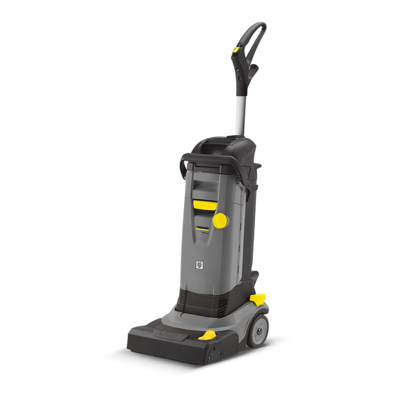
Setup and function Front view (BR 30/4 C Adv and BR 30/4 C) 1 Handle 2 Cable hook 3 Main switch for brushing/vacuuming operations 4 Fresh water tank lock 5 Release, park position 6 Vacuum bar lift pedal 7 Cleaning head... -
Page 6: Front View (Br 30/4 C Bp Pack)
Front view (BR 30/4 C Bp Pack) 1 Handle 15 Battery 2 Main switch for brushing/vacuuming operations 16 Mains connection 3 Fresh water tank lock 17 Charger 4 Release, park position 18 Battery charge indicator 5 Vacuum bar lift pedal... -
Page 7: Front View (Br 30/4 C Bp Pack Power +)
Front view (BR 30/4 C Bp Pack Power +) 1 Handle 15 Charger 2 Water pump switch 16 Vacuum bar lift pedal 3 Main switch for brushing/vacuuming operations 17 Indicator lamp 4 Release of fresh water reservoir 18 Mains connection... -
Page 8: Rear View (Br 30/4 C Adv And Br 30/4 C / Br 30/4 C Bp Pack)
Rear view (BR 30/4 C Adv and BR 30/4 C / BR 30/4 C Bp Pack) 1 Handle 2 Cable hook 3 Cable hook, rotating 4 Vacuum nozzle intake 5 Exhaust air cover 6 Suction hose 7 Release, park position... -
Page 9: View From Below
View from below 1 Park roller 2 Space roller 3 Rear vacuum bar 4 Brush roller 5 Front vacuum bar 6 Space roller The spacer rollers prevent the cleaning head from scrap- ing on the floor when the brush is worn. English 5.906-768.0 Rev. -
Page 10: Function
Function 4.6.1 Parking/operating position 4.6.3 Removing the tanks 1 waste water tank To operate, the release of the parking position must be 2 Fresh water tank pressed (small arrow) and the appliance has to be swiv- 3 Wastewater inlet opening with seal elled back simultaneously. - Page 11 To fill the fresh water tank, open the latch and fill the The spring element pushes the waste water tank down. fresh water tank with water and detergent. This will prevent damage to the seal rings during the instal- lation of the waste water tank.
-
Page 12: Insert Suction Nozzle (Br 30/4 C Adv Only)
The waste water tank needs to be emptied. 4.6.4 Insert suction nozzle (BR 30/4 C Adv only) With model BR 30/4 C Adv, a suction nozzle can be at- tached to vacuum in corners. 1 Suction pipe holder 2 Suction tube ... -
Page 13: Water Flow Schematic
4.6.5 Water flow schematic 4.6.6 Remove the cover from the cleaning head 1 Cover of cleaning head 2 Vacuum bar lift pedal Remove the cover from the cleaning head toward the top. The cover has several hooks that lock into the cleaning head. -
Page 14: Replace The Batteries (Br 30/4 C Bp Pack Only)
4.6.7 Replace the batteries (BR 30/4 C Bp Pack 4.6.9 LED display on the brush head (BR 30/4 C only) Bp Pack only) 1 LED status indicator 2 Battery storage 3 Battery 4.6.10 LED display on the brush head (only... -
Page 15: 4.6.11 Display On The Battery
3 LEDs light up: Voltage above 37.3 volts. – If the battery is empty, the machine switches off after 30 seconds. BR 30/4 C Bp Pack Power+ 1 Battery 2 LED status indicator 3 PRÜFTASTE/ TESTBUTTON The equipment electronics checks the battery's charging state. -
Page 16: Displays On The Charger (Br 30/4 C Bp Pack Only)
Figure F pack and dispose of it properly. When the battery pack is fully charged, the green LED – 4.6.12 Displays on the charger (BR 30/4 C Bp glows. The charger automatically switches to retention Pack only) charging. Remove the battery pack and insert it in the device. -
Page 17: Control Board (Br 30/4 C Bp Pack Only)
The printed circuit board allows the safe and reliable oper- ation of the battery-powered BR 30/4 via voltage and cur- rent measurement. 5.1.15Replace the control board (BR 30/4 C Bp Pack only) 5.1.16Replace control board (only BR 30/4 C Bp Pack Power +) English 5.906-768.0 Rev. -
Page 18: Basic Settings And Service Procedures
NOTICE For the BR 30/4 Bp, the switch must be pressed for >300 msec for the appliance to be switched on. BR 30/4 C Bp Pack 1 Housing top 2 Spring element Remove the waste water tank (see chapter "Removing the tanks"). -
Page 19: Replacing The Water Pump Switch
5.1.2 Replacing the water pump switch 5.1.3 Replacing the brush roller intake 1 Fastening screws (3x), housing cover 2 Covering lid 3 Water pump switch Unscrew the screws. 1 Fastening screws (3x), cover 2 Cover Unscrew the screws. ... -
Page 20: Replacing The Brush Roller
3 Toothed belt disc Install the new brush roller in reverse order. 4 Outer ball bearing When inserting the brush roller, make sure that the tow- ing is properly placed in the brush roller. Install the new drive unit in reverse order. 5.1.5 Replacing the water distribution bar 5.1.4... -
Page 21: Removing The Cleaning Head Housing
Move the pedal for the vacuum bar lift to the pedal po- sition "vacuum bar lowered" (see Chapter "Raising/low- ering the vacuum bar“). Pull the vacuum bar out of the vacuum bar support. Insert the new vacuum bar from the bottom into the vac- 1 Fastening screws (2x) per side, cleaning head housing uum bar support from the bottom and press upward, 2 Mount, release park position... -
Page 22: Replacing The Water Pump
5.1.9 Voltage measurement on the water pump NOTICE BR 30/4 C onlyBp Pack: The connection voltage of 24 Volts is pulsed; therefore, only about 12 Volts can be measured on the water pump. This water pump does not have a diode. The water pump is monitored by current. - Page 23 1 Toothed belt to the brush roller drive 2 Drive unit, brush roller 1 Toothed belt, from suction turbine 2 coupling 3 Fastening screws (4x), half bearings 4 Half bearings 5 Toothed belt to the brush roller drive Unscrew the screws. ...
-
Page 24: 5.1.11 Replace The Coupling
3 Toothed belt to the brush roller drive 5.1.12 Replacing the suction turbine Remove the coupling toward the top. Remove both toothed belts. Install the new toothed belts in reverse order. NOTICE The coupling is triggered in case of an overload and emits very loud noises. - Page 25 1 Bottom half bearing, suction turbine housing 2 Suction turbine (M1) Remove the suction turbine from the bottom half bowl. 1 Bearing ring (2x), axle Remove the bearing ring from both sides. 1 Suction turbine (M1) 2 Lock (2x), housing cover 3 Covering lid 4 Bottom housing part ...
-
Page 26: 5.1.13 Remove The Parking Position Release
Flush the suction hose and the suction channel with water or pull or push the obstruction out with a blunt ob- ject (such as a cable tie or a similar object). 5.1.15 Replace the control board (BR 30/4 C Bp Pack only) DANGER Turn the appliance off and remove the accumulator prior to performing any tasks on the appliance. - Page 27 1 Screws 1 Electric socket plug connections 2 Circuit board cover 2 Electric screw connections 3 Release, park position 3 Control board Press the park position release and tilt the appliance Only touch the control board on the outer edges. backwards.
-
Page 28: Replace Control Board (Only Br 30/4 C Bp Pack Power +)
The control board must be reinserted into the guides. 5.1.16 Replace control board (only BR 30/4 C Bp Ensure that the cable inlet is seated properly. Pack Power +) DANGER Turn the appliance off and remove the accumulator prior to performing any tasks on the appliance. -
Page 29: Troubleshooting
Remedy Appliance cannot be started Check power connection/conduit. Check/replace the main switch Check/insert the batteries,charge them as necessary (BR 30/4 C Bp Pack only) No or insufficient water supply Fill up fresh water reservoir. Check/clean the water outlet valves on the fresh water reservoir. - Page 30 English 5.906-768.0 Rev. 01 (10/20)
-
Page 31: Circuit Diagram
Circuit diagram Circuit diagram 0.089-099.0 - BR 30/4 C (230V/50-60 Hz), BR 4.300 g n / g e 3 X 1 q m m 2 3 0 V / 5 0 / 6 0 H z 1 6 A - S 1... -
Page 32: Circuit Diagram 0.089-149.0 - Br 30/4 C (120 V/60 Hz)
Circuit diagram 0.089-149.0 - BR 30/4 C (120 V/60 Hz) g n / g e 3 X 1 8 A W G 1 2 0 V / 6 0 H z 1 5 A - S 1 - S 2... -
Page 33: Circuit Diagram 0.089-150.0 - Br 30/4 C (100V/50-60 Hz)
Circuit diagram 0.089-150.0 - BR 30/4 C (100V/50-60 Hz) g n / g e 3 X 0 , 7 5 m m ² 1 0 0 V / 5 0 / 6 0 H z - S 1 - S 2 0 , 7 5 m m ²... -
Page 34: Circuit Diagram 0.089-811.0 - Br 30/4 C Bp Pack
Circuit diagram 0.089-811.0 - BR 30/4 C Bp pack Control board Battery Brush motor Water pump Main switch for brushing/vacuuming operations Water pump switch Connector 3 pin English 5.906-768.0 Rev. 01 (10/20) -
Page 35: Circuit Diagram 0.090-099.0 - Br 30/4 C Bp Power
Circuit diagram 0.090-099.0 - BR 30/4 C Bp Power+ Control board Battery Brush motor Water pump Main switch for brushing/vacuuming operations Water pump switch Connector 2 pin English 5.906-768.0 Rev. 01 (10/20) - Page 36 Technical specifications BR 30/4 C - power models BR 30/4 C Bp Pack Power Power Nominal voltage Nominal voltage 220...240 Average power consumption Protective class Frequency 1~ 50/60 Type of protection IPX4 Average power consumption Vacuuming Protective class Cleaning power, air quantity...
- Page 37 BR 30/4 C Bp Pack Power+ Power Nominal voltage Average power consumption Current consumption at 35 V 16.7 Protective class Type of protection IPX4 Vacuuming Cleaning power, air quantity Cleaning power, negative pres- sure Cleaning brush Working width Brush diameter...
Need help?
Do you have a question about the BR 30/4 C and is the answer not in the manual?
Questions and answers