Advertisement
Quick Links
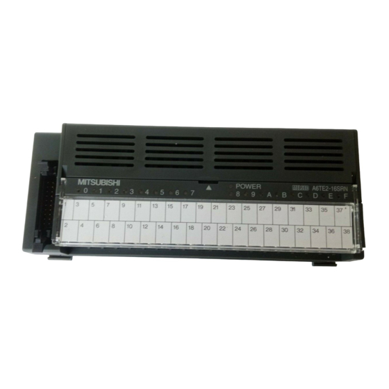
Relay Terminal
Thank you for buying the Mitsubishi general-purpose programmable
controller MELSEC-A Series
Prior to use, please read both this manual and detailed manual
thoroughly and familiarize yourself with the product.
©1997 MITSUBISHI ELECTRIC CORPORATION
User's Manual
A6TE2-16SRN
MODEL
A6TE2-16SRN-U-E
MODEL
CODE
IB (NA)66833-F (1112) MEE
Module
(Hardware)
13JL53
Advertisement

Related Manuals for Mitsubishi A6TE2-16SRN


Summary of Contents for Mitsubishi A6TE2-16SRN
- Page 1 Relay Terminal Module User’s Manual (Hardware) A6TE2-16SRN Thank you for buying the Mitsubishi general-purpose programmable controller MELSEC-A Series Prior to use, please read both this manual and detailed manual thoroughly and familiarize yourself with the product. MODEL A6TE2-16SRN-U-E MODEL 13JL53...
-
Page 2: Safety Precautions
SAFETY PRECAUTIONS (Read these precautions before using this product.) Before using this product, please read this manual and the relevant manuals carefully and pay full attention to safety to handle the product correctly. The instructions given in this manual are concerned with this product. For the safety instructions of the programmable controller system, please read the CPU module user's manual. - Page 3 [INSTALLATION PRECAUTIONS] CAUTION Use the module in the environment given in the general specifications of CPU module user's manual. Using the programmable controller outside the range of the general specifications may result in electric shock, fire or malfunction, or may damage the product. Load a cable by inserting to a module connector until a clicking sound comes.
- Page 4 [STARTING AND MAINTENANCE PRECAUTIONS] WARNING Do not touch the terminals while the power is on. Doing so may cause electric shock or malfunction. Switch off all phases of the externally supplied power used in the system when cleaning the module or retightening the terminal or module mounting screws. Not doing so could result in electric shock.
-
Page 7: Conditions Of Use For The Product
PRODUCT in one or more of the Prohibited Applications, provided that the usage of the PRODUCT is limited only for the specific applications agreed to by Mitsubishi and provided further that no special quality assurance or fail-safe, redundant or other safety features which exceed the general specifications of the PRODUCTs are required. - Page 8 This User's Manual explains the specifications and part identification of A6TE2-16SRN Relay Terminal Module (abbreviated as A6TE2-16SRN hereafter). The A6TE2-16SRN is used in place of a joint terminal block and in-panel relay. It reduces wiring work processes for the programmable controller, joint terminal block and in-panel relay.
-
Page 9: Performance Specifications
6) Because it can be replaced by a relay output, it can be used either for AC or DC with larger current capacity. 7) Self-up screws are adopted so that the terminal screws do not fall off. 8) Wiring works have been simplified by the indication on the symbol sheet of the relay terminal module. - Page 10 Contact current (A) Figure 2.1 Electrical Life Curve of a Relay 2) Do not use A6TE2-16SRN under pressure higher than the atmospheric pressure of 0m (0ft.) altitude. Doing so can cause a malfunction. When using A6TE2-16SRN under pressure, please consult your sales...
- Page 11 3. Part Identification and External Dimensions MITSUBISHI POWER (7.1) When the terminal cover is open (30.1) 52.6 (2.1) (1.6) (1.2) DIN rail (56.3) (2.2) When a DIN rail is installed (Unit:mm(in)) View from A) COM1 +24V COM3 COM2 COM2 COM2 COM2 COM2 COM2 COM2 COM2 COM2 COM4 COM4 COM4 COM4 COM4 COM4 COM4 COM4...
- Page 12 4. Wiring 4.1 Wiring Use the connection cables descried in Section 4.2, and wire them as shown in Figure 4.1. COM1 COM3 Y8 Y9 YA YB YC YD YE YF Y0 Y1 Y2 Y3 Y4 Y5 Y6 Y7 +24V C2 C2 C2 C2 C2 C2 C2 C2 COM2 COM4 C4 C4 C4 C4 C4 C4 C4 C4...
-
Page 13: Installation
(Y0 to YF) Figure 4.2 Connection Cable (Unit: mm (in)) 5. Installation 5.1 Installation Orientation Figure 5.1 shows the orientation of installation. a) Vertical orientation: Correct b) Vertical orientation: Correct MITSUBISHI POWER c) Vertical orientation: Correct d) Vertical orientation: Incorrect... - Page 14 e) Horizontal orientation: Correct f) Horizontal orientation: Incorrect Figure 5.1 Installation Orientation (Horizontal view) Point Confirm that the relay is securely installed before turning on the power supply for the first time after shipment. 5.2 Replacing the Relay The relay is replaced in the following manner. 1) Open the top cover of the module.
- Page 15 Figure 5.4 Removal Procedure from a DIN Rail 6. Precautionary Items for Relay Replacement When the A6TE2-16SRN relay is replaced, always use a relay that is compatible with the A6TE2-16SRN. The following table shows the relationship between the relay terminal module types and applicable relays for replacement.
- Page 16 WARRANTY Mitsubishi will not be held liable for damage caused by factors found not to be the cause of Mitsubishi; machine damage or lost profits caused by faults in the Mitsubishi products; damage, secondary damage, accident compensation caused by special factors unpredictable by Mitsubishi;...
Need help?
Do you have a question about the A6TE2-16SRN and is the answer not in the manual?
Questions and answers