Table of Contents
Advertisement
User's Manual
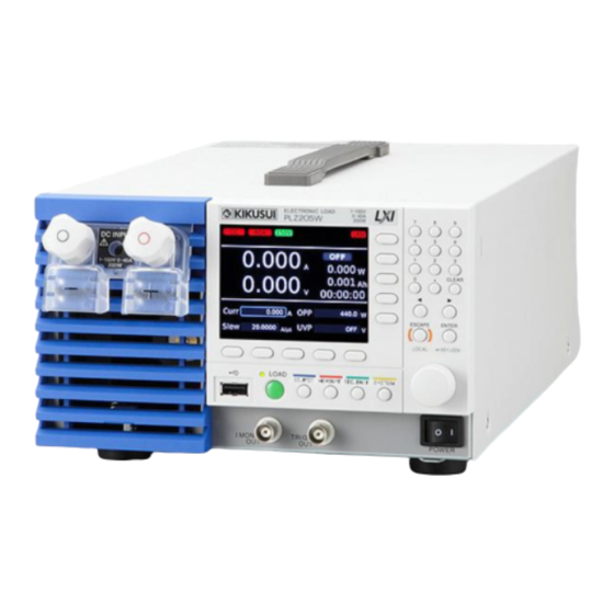
PLZ-5W Series Electronic Load
PLZ205W
PLZ405W
PLZ1205W
PART NO. IB027941
Mar. 2016
Component Names 8
Maintenance 95
Appendix 107
Contents 5
Advertisement
Table of Contents

Related Manuals for Kikusui PLZ-5W Series


Summary of Contents for Kikusui PLZ-5W Series
-
Page 1: Table Of Contents
PART NO. IB027941 Mar. 2016 Contents 5 User’s Manual Component Names 8 PLZ-5W Series Electronic Load PLZ205W Installation and Preparation 12 PLZ405W Basic Functions 19 PLZ1205W Advanced Functions 41 Sequence Function 55 External Control 69 Parallel Operation 80 System Settings 84... -
Page 2: About Operation Manual
Both unit specifications and manual contents are subject to change without notice. Manual construction © 2016 Kikusui Electronics Corporation • User's manual (this manual) This document is intended for first-time users of this prod- uct. It provides an overview of the product, notes on usage, and specifications. -
Page 3: Checking The Package Contents
In addition to basic constant current, constant resistance, con- Top [Q1-500-156] stant voltage, and constant power modes, the PLZ-5W Series offers a variety of other features. The PLZ-5W series also pro- vides better performance than previous models. [M5-101-008] High-speed response... -
Page 4: Notations Used In This Manual
Notations Used in This Manual Safety Precautions • In this manual, electronic loads PLZ205W, PLZ405W, and When using this product, be sure to observe the “Safety Pre- PLZ1205W are sometimes referred to as “PLZ-5W”. cautions” in the Safety information manual. The following pre- cautions pertain only to this product. -
Page 5: Contents
Obtaining the measurement data......Setting triggers............. Preparation Recording Integrated Data ......39 Recording current capacity/power capacity/elapsed Rack Mounting the PLZ-5W Series....12 time..............Removing the handle and the rubber feet ... Displaying the integrated data ......Attaching the rack adapter or bracket.... - Page 6 Ratings ..............Trigger output ............Constant current (CC) mode ....... Digital I/O ............78 Constant resistance (CR) mode ......Constant voltage (CV) mode ....... Using the Current Monitor Signal..... 79 Constant power (CP) mode ....... Current monitor output ......... PLZ-5W series...
- Page 7 Parallel operation using the same type of electronic loads..............Parallel operation using boosters ...... Options............129 Rack adapters, brackets ........GPIB converter (PIA5100) ......... Parallel operation signal cable kit (PC01-PLZ-5W) ... Low inductance cable ........Large current load cable ........INDEX ..............131 PLZ-5W series...
-
Page 8: Component Names
Component Names Front panel PLZ205W PLZ405W (PLZ205W example) PLZ1205W Name Function Protection plate This plate protects the load input terminal on the front panel. The DUT and the p.17 PLZ-5W can be connected by removing the protection plate and attaching the front panel load input terminal cover. - Page 9 Controls No. Name Function Display Displays the settings, measured values, and other information. p.10 Function keys Each function key executes the item that is displayed above that key (function area). p.19 Sub-function keys Each sub-function key executes the item that is displayed to the left of that key p.19 (sub-function area).
- Page 10 Display Name Function Setting of operation mode Displays the currently selected operation mode. p.21 Current range Displays the current range. p.27 Voltage range Displays the voltage range. p.27 Remote control mode Indicates that the product is being controlled remotely. p.54 Operation mode Displays the currently running operation mode.
- Page 11 Rear panel PLZ205W PLZ405W (PLZ205W example) 8 9 10 PLZ1205W 8 9 10 Name Function EXT CONT connector External control connector. A cover for the pins is provided. p.69 SENSING connector Remote sensing connector. p.43 DC OUT connector Used during GPIB converter (option) use. p.130 DC INPUT terminal Used to connect the DUT and the PLZ-5W.
-
Page 12: Installation And Preparation
Installation and Preparation Rack Mounting the PLZ-5W Series The PLZ-5W can be rack mounted using the optional rack adapter or the optional bracket (p.129). To rack mount the PLZ-5W, remove the handle of the PLZ-5W and the rubber feet. Removing the handle and the rubber feet •... -
Page 13: Connecting The Power Cord
If the supplied power cord cannot be used because the rated voltage or the plug shape is incompatible, have a qualified engineer replace it with an appropriate power cord that is 3 m or less in length. If obtaining a power cord is difficult, contact your Kikusui agent or dis- tributor. -
Page 14: Checking Whether The Power Is On Or Off
(However, the load setting is always Load Off.) The panel setting state at startup can be changed (p.85). If the PLZ-5W does not start normally If the following remedy does not solve the problem, contact your Kikusui agent or distributor. Status Remedy Nothing is shown on the display. -
Page 15: Connecting To The Load Input Terminals
Connecting to the Load Input Terminals The PLZ-5W has load input terminals on both its front and rear panels. The specifications of the PLZ-5W are for the load input terminals on the rear panel. For information on selecting load cables, refer to “Appendix” (p.107) in the “Selecting the Load Cables”. - Page 16 Connecting to the Load Input Terminals 1.Installation and Preparation Attaching the load input terminal cover You can adjust the diameter of the holes that the load cables pass through by changing the positions in which the top and bottom load input terminal covers are put together. There are two available positions.
-
Page 17: Connecting To The Load Input Terminals On The Front Panel
1.Installation and Preparation Connecting to the Load Input Terminals Connect the load cables to the output terminals of the DUT. Connect the positive (+) polarity of the load input terminal on the rear panel to the pos- − itive (+) polarity of the DUT, and the negative ( ) polarity of the load input terminal on −... -
Page 18: Notes Regarding Load Input Terminals
Connecting to the Load Input Terminals 1.Installation and Preparation Insert the load cables from the bottom and tighten the accessory knobs to fix the cables in place. knob knob Black ( ) Red ( + ) Connect the load cables to the output terminals of the DUT. Connect the positive (+) polarity of the load input terminal on the front panel to the −... -
Page 19: Basic Functions
Basic Functions Panel Operations The PLZ-5W is controlled from the operation panel on the front panel. Using the function keys Switching the display The following two display methods are available. Display method Description Main display Displays the measurement values and settings in a large size. Function display Zooms out of the display of measurement values and settings, and displays a menu allowing execution with function keys/sub-function keys. -
Page 20: Inputting Numbers/Characters
Load On/Load Off 2.Basic Functions Inputting numbers/characters Front panel If a cursor appears on the display, you can enter numbers. Depending on the input location, the input of alphabetic charac- ters and symbols may be possible. Cursor Purpose Operation Description Numeric/charac- Numeric keypad Following input, press ENTER to confirm the input. -
Page 21: Setting The Operation Mode
Setting the Operation Mode The following five operation modes are available on the PLZ-5W. Mode switching can be done only while the load is off. Constant current (CC) mode A current value is specified and the current is kept constant even when the voltage changes. -
Page 22: Setting Constant Voltage (Cv) Mode
Setting the Operation Mode 2.Basic Functions Setting constant voltage (CV) mode In constant voltage (CV) mode, the PLZ-5W sinks current so that the voltage at the load input end of the PLZ-5W is constant (p.116). Press SOURCE, Mode, Next, and then CV. “CV”... -
Page 23: Adding Cv Mode To Cc Mode (Cc+Cv)
2.Basic Functions Setting the Operation Mode Adding CV mode to CC mode (CC+CV) Constant voltage (CV) mode can be added while constant current (CC) mode is set (p.118). CV mode can be added even while the load is turned on. Set CC mode. -
Page 24: Adding Cv Mode To Cr Mode (Cr+Cv)
Setting the Operation Mode 2.Basic Functions Adding CV mode to CR mode (CR+CV) Constant voltage (CV) mode can be added while constant resistance (CR) mode is set (p.119). CV mode can be added even while the load is turned on. Set CR mode. -
Page 25: Setting Arbitrary I-V Characteristics (Arb) Mode
2.Basic Functions Setting the Operation Mode Setting arbitrary I-V characteristics (ARB) mode In arbitrary I-V characteristics (ARB) mode, arbitrary I-V characteristics can be set by registering multiple I-V characteristic points (set of voltage value and current value). Three up to 100 points can be registered, and the space between two points is linearly interpolated. This mode can be used for simulation of LED loads and the like. - Page 26 Setting the Operation Mode 2.Basic Functions Example: Setting I-V characteristics Example of settings Voltage [V] Current [A] You can smoothly set the I-V characteristics by first setting the row with the maximum voltage, and then proceeding to set the 0.02 other values in decreasing order.
-
Page 27: Setting The Current Range / Voltage Range
Setting the Current Range / Voltage Range The current range and voltage range can be set when the load is off. Press SOURCE and then Range. Use the sub-function keys to set the current range and the voltage range. L range Current Range M range H range... -
Page 28: Setting The Short Function
(30 V /1 A) of the EXT CONT connector (p.71) closes. The load input terminals can be shorted by driving an external high-current relay or the like. PLZ-5W Series EXT CONT connector Relay on the rear panel – –... -
Page 29: Switching Function
Switching Function Switching refers to the operation of executing two settings repetitively. The switching function is suitable for transient response characteristics testing of regulated DC power supplies. The switching function operates in CC mode and CR mode. This function can be set regard- less of whether the load is on or off. - Page 30 Switching Function 2.Basic Functions Setting the switching interval with the duty ratio Set the frequency (or the time of one cycle) and duty ratio. Press SOURCE, Switching, and then Freq. Use the numeric keypad or the rotary knob to enter the frequency (1 Hz to 100 kHz).
-
Page 31: Turning The Switching Function On/Off
2.Basic Functions Switching Function Press Duty twice. The display switches from Duty [%] to Th [s]. Use the numeric keypad or the rotary knob to enter the HIGH side opera- tion time. This sets the switching interval. Turning the switching function on/off After setting the switching level and the switching interval, turn the switching function on. -
Page 32: Alarm Function
Alarm Function This function detects anomalies and protects the DUT. Alarm types and operation There are two types of alarm based on urgency level: alarm 1 (high urgency) and alarm 2 (low urgency). Alarm 1 (high urgency) This alarm detects anomalies and automatically turns off the load. The operating conditions of this alarm are fixed. -
Page 33: Setting Overcurrent Protection (Ocp)
2.Basic Functions Alarm Function Setting overcurrent protection (OCP) This function either puts a limit on the current (OCPL) or turns off the load of the PLZ-5W (OCPT) when a current that is equal to or exceeds the set value is running through the PLZ- 5W. -
Page 34: Setting Undervoltage Protection (Uvp)
Alarm Function 2.Basic Functions Use the numeric keypad or the rotary knob to enter the power value. Press Action and select the operation when an alarm occurs. The setting switches each time you press Action. Item Description Trip Turns the load off. The display changes to “OPPT”. Limit Limits the current so as not to exceed the set value. -
Page 35: Setting Watchdog Protection (Wdp)
2.Basic Functions Alarm Function Setting watchdog protection (WDP) This function turns off the load of the PLZ-5W when SCPI communication is performed for a length of time that is equal to or exceeds the WDP setting. Press SYSTEM. If the Configure screen does not appear, press Configure Interface. Use the rotary knob to select Delay under Watchdog, and then press Edit. -
Page 36: Measurement Function
Measurement Function Overview of the measurement function The PLZ-5W shows the latest measured values (current, voltage, power) on the display. It can also store them in the internal memory (data logging function). Recorded measurement values are obtained by remote control. By setting triggers (p.37), you can also control the timing that measurement values are recorded. -
Page 37: Setting Triggers
2.Basic Functions Measurement Function Setting triggers By setting triggers, you can control the number of times that measurement values are to be acquired, the acquisition timing, and so on. Moreover, you can also change the events that constitute the conditions for measurement value acquisition (trigger sources). Press MEASURE and then Acquire. - Page 38 Measurement Function 2.Basic Functions Trigger processing procedure The general trigger processing procedure is illustrated in the following figures. Abort Power ON Press Initiate count=0 Immediate DIGITAL2 Source Event detector TALink MSync Delay Other Immediate Trigger source Disable Enable timer= Interval Interval Time? timer = 0...
-
Page 39: Recording Integrated Data
Recording Integrated Data Recording current capacity/power capacity/elapsed time Current capacity, power capacity, and elapsed time (hereafter, integrated data) starts/stops being recorded in synchronization with load on/off in the factory default condition. Moreover, at the start of recording, the data is automatically reset. You can change the integrated data recording method, selecting for example manual recording start/stop/reset. -
Page 40: Displaying The Integrated Data
Recording Integrated Data 2.Basic Functions Press Start. Integrated data recording starts. Press Stop. Integrated data recording stops. Resetting integrated data manually In the integrated data recording method, if “Reset” is set to “Manual”, the integrated data can be reset manually. Press MEASURE and then Data. -
Page 41: Advanced Functions
Advanced Functions Changing the Response Speed Set the response speed for the constant voltage (CV) mode or constant resistance (CR) mode according to the conditions and purpose of use of the DUT. The factory default setting is “Normal”. You can make the response speed faster by setting “Fast”. -
Page 42: Soft Start
Soft Start Soft start is a function that controls the rise time of the load current. Soft start functions only when all the following conditions are met. • The rise time of the soft start has been set. • Load on state in constant current (CC) mode. •... -
Page 43: Remote Sensing
Remote Sensing A voltage measurement point can be changed from a load input terminal to an arbitrary sensing point by executing remote sensing. By setting sensing points to a DUT end, influences such as voltage drops caused by the resistance of the load cables can be reduced and the load current can be stabilized. -
Page 44: Enabling Remote Sensing
Remote Sensing 3.Advanced Functions Attach the sensing terminal cover. Connect the sensing cables to the DUT. Connect the positive (+S) polarity of the SENSING terminal to the positive (+) polarity of the DUT, and connect the negative (-S) polarity of the SENSING terminal to the neg- −... -
Page 45: Trigger Function
Trigger Function The PLZ-5W allows you to control the start timing of measurement, sequences and step using triggers. By enabling the trigger function, a measurement or a sequence can be started when an event selected beforehand (trigger source) matches an event either inside or out- side the PLZ-5W (trigger). -
Page 46: Types Of Memory
Types of Memory The PLZ-5W has two types of memory, ABC preset memories and setup memory. ABC preset memories Basic settings (current, voltage, conductance, power) can be saved to three memories, A, B, and C. Because you can recall saved settings just by pressing a key, this feature is very useful when you want to switch between three different types of output in order. -
Page 47: Abc Preset Memories
ABC Preset Memories Load settings can be saved to three memories, A, B, and C. In CC mode, CR mode, CP mode, the load settings for each current range can be saved. In CV mode, the load settings for each voltage range can be saved. In ARB mode, you can save the number of Table rows and load settings. -
Page 48: Recalling Abc Preset Memory Entries
Setup Memory 3.Advanced Functions Recalling ABC preset memory entries You can recall settings regardless of whether the load is on or off. • Alarm detection points are not saved to ABC preset memories. If the settings that you recall cause alarm detection points to be exceeded, an alarm will occur. Sets the operation mode and range. -
Page 49: Recalling The Setup Memory
3.Advanced Functions Setup Memory Use the rotary knob to select the setup memory. Press Save. The setting contents are saved to the setup memory. Recalling the setup memory You can recall memory content when load is turned off. Press SYSTEM and then Recall Save. Use the rotary knob to select the setup memory. -
Page 50: Synchronized Operation
(p.130) can be used as the connection cable. To use a LAN cable more than 30 m long, please contact your Kikusui agent or distributor. Risk of electric shock. WARNING • Do not touch the IN/OUT terminals of EXT SYNC while the PLZ-5W is turned ON. -
Page 51: Synchronizing The Load On/Off Operation
3.Advanced Functions Synchronized Operation Connect all the PLZ-5W units with LAN cables. Connect the OUT port of EXT SYNC of a PLZ-5W unit to the IN port of EXT SYNC of another unit with a LAN cable. After performing the connection, be sure to attach the SYNC/PARALLEL port cover while referring to step 3. -
Page 52: Synchronizing Measurements
Synchronized Operation 3.Advanced Functions Synchronizing measurements The recording timing of measured values can be synchronized on multiple synchronized PLA-5Ws (p.50). Press MEASURE and then Acquire. Use the rotary knob to select Source, and then press Edit. Use the rotary knob to select MSync, and then press ENTER. Press Initiate. -
Page 53: Synchronizing The Resuming Of Sequences
3.Advanced Functions Synchronized Operation Synchronizing the resuming of sequences The sequence pause (trigger wait) timing can be synchronized on multiple synchronized PLZ- 5Ws (p.50). Create a program (p.56). Create steps, and set Wait(pre) in the step to be paused to MSync (p.60). Perform step 1 and step 2 on all PLZ-5Ws to be synchronized. -
Page 54: Remote Control
Remote Control In addition to using the front panel, you can also control the PLZ-5W remotely by sending commands. For details on remote control, see the Communication Interface Manual on the included CD-ROM. The following environment is required to view the Communication Interface Manual. Browser: Internet Explorer 11 or later PDF reader: Adobe Reader 9.2 or later Releasing remote control... -
Page 55: Sequence Function
Sequence Function Overview of the Sequence Function Sequence is a function that executes a sequence of operations set in advance. Programs and steps A sequence consists of programs and steps. A program is a collection of steps. Steps are executed in order one at a time, starting from step 1. Upon completion of the last step of a program, execution of that program has been completed once. -
Page 56: Program Settings
Program Settings Different programs can be created for each operation mode. How to view the program editing screen Press SEQUENCE and then Program to display the sequence editing screen. When you change the operation mode (p.21), programs that were created in each operation mode are displayed. -
Page 57: Setting The Number Of Loops Of A Program
4.Sequence Function Program Settings Setting the number of loops of a program Press SEQUENCE and then Program. Use the rotary knob to select the program, and then press Select. A check mark appears to the left of the selected program name. Press Steps, Property and then Loop. -
Page 58: Setting Protection Functions
Program Settings 4.Sequence Function Setting protection functions You can set overcurrent protection (OCP), overpower protection (OPP), and undervoltage protection (UVP) in a program. The protection functions that you can set varies depending on the operation mode. Press SEQUENCE and then Program. Use the rotary knob to select program, and then press Select. -
Page 59: Deleting A Program
4.Sequence Function Program Settings Deleting a program Press SEQUENCE and then Program. Use the rotary knob to select the program, and then press Delete. If the check box of any program is selected, you cannot delete programs. If a check box is selected, use the rotary knob to select the corresponding program, and then press Select to clear the check box. -
Page 60: Setting Steps
Setting Steps Creating steps Press SEQUENCE and then Program. Use the rotary knob to select the program, and then press Select. A check mark appears to the left of the selected program name. Press Steps. The step editing screen appears. To insert a new step, press Insert. - Page 61 4.Sequence Function Setting Steps Step transition method The available load setting transition methods are Ramp and Immediate. With Immediate, the load setting transitions step-wise from the setting of the previous step. With Ramp, the load setting transitions in a ramp from the setting of the previous step. For step 1, the load setting start point is 0 A, 0 S, 0V, or 0 W.
-
Page 62: Deleting A Step
Sequence creation tutorial 4.Sequence Function Deleting a step Press SEQUENCE and then Steps. Use the rotary knob to select the step, and then press Delete. The selected step is deleted. Press Save. The steps are registered to the program. Sequence creation tutorial In this example, we will actually create a sequence from the operation panel. -
Page 63: Newly Creating Program1
4.Sequence Function Sequence creation tutorial Newly creating program1 Sets the operation mode to CC mode (p.21). Press SEQUENCE, Program, and then Create. Use the numeric keypad or the rotary knob to enter program name “Program1”, and then press ENTER. Program1 is created. Registering steps to program1 Creating step 1 Use the rotary knob to select Program1, and then press Select. - Page 64 Sequence creation tutorial 4.Sequence Function Creating step 2 Press Insert. Step 2 is inserted. Use the rotary knob and the ← key to select a cell in the Level column of Step 2 (2nd row), and then press Edit. Use the numeric keypad or the rotary knob to enter current value “6”, and then press ENTER.
- Page 65 4.Sequence Function Sequence creation tutorial Creating step 4 Press Insert. Step 4 is inserted. Use the rotary knob and the ← key to select a cell in the Level column of Step 4 (4th row), and then press Edit. Use the numeric keypad or the rotary knob to enter current value “3”, and then press ENTER.
-
Page 66: Executing, Pausing, And Stopping Sequences
Executing, Pausing, and Stopping Sequences When setting of the programs and steps is completed, the sequence is executed. Pauses and stops can be executed during sequence execution. Executing a sequence During sequence execution, the switching function and short function are forcibly turned off. The sequence can be executed regardless of whether the load is on or off. -
Page 67: Stopping A Sequence
4.Sequence Function Executing, Pausing, and Stopping Sequences Stopping a sequence Pressing Abort during sequence execution stops the sequence execution that is in progress (if the load is on, it remains on as is). Setting triggers By setting triggers, you can control the timing at which sequences are to be started. In addition, you can set an event (trigger source) that will be used as a condition for starting sequences. - Page 68 Executing, Pausing, and Stopping Sequences 4.Sequence Function Trigger processing procedure The general trigger processing procedure is illustrated in the following figures. POWER switch on Initiate key press Immediate Source Event detector DIGITAL2 MSync Delay Sequence start Trigger application examples Example: Immediate is set for Source.
-
Page 69: External Control
External Control Preparation for External Control By connecting the rear-panel EXT CONT connector, front-panel BNC terminals (I MON OUT connector, TRIGOUT connector) to an external device with signal cables, you can control and monitor the PLZ-5W from the external device (external control). The BNC terminals are isolated from the chassis and load input terminals. -
Page 70: Connecting The Ext Cont Connector
By factory default, the protection plate is mounted on the EXT CONT connector. When using the EXT CONT connector, keep the removed protection plate in a safe place. If it is damaged or lost, contact your Kikusui agent or distributor. External control connector kit To connect the signal cable to the EXT CONT connector, use the external control connector kit that comes with the PLZ-5W. -
Page 71: Ext Cont Connector Pin Arrangement
5.External Control Preparation for External Control EXT CONT connector pin arrangement EXT CONT connector pin number Pin no. In/Out Signal name Description STATUS COM Status signal common for pins 2, 3, 14 to 16. RANGE STATUS 0 Range status output (p.76). RANGE STATUS 1 RANGE CONT 0 Range switch input (p.76). -
Page 72: Load Setting Control
Load Setting Control Constant current (CC), constant resistance (CR), and con- stant power (CP) control You can control the load setting of CC, CR, and CP modes using external voltage. When you apply an external voltage between 0 V to 10 V to the EXT CONT connector, a load setting proportional to the change can be obtained. -
Page 73: Constant Voltage (Cv) Control
5.External Control Load Setting Control Constant voltage (CV) control You can control the voltage in CV mode, CC+CV mode, or CR+CV mode using external volt- age. When you apply an external voltage of 0 V to 10 V to the EXT CONT connector, the volt- age varies proportionally to that external voltage. -
Page 74: Controlling The Current To Be Superimposed On The Constant Current (Cc)
Load Setting Control 5.External Control Controlling the current to be superimposed on the constant current (CC) You can control the current to be superimposed to the current value of CC mode with an external voltage. When you apply an external voltage between 0 V to 10 V to the EXT CONT connector, the load current becomes the sum of the current proportional to the external voltage change and the Present current setting. -
Page 75: Control Of Load On/Load Off
Control of Load On/Load Off You can control load on and load off with an external signal. You can also monitor the load on/off state. Load on/off control input You can externally control load on and load off with an external signal, by using an external contact. -
Page 76: Load-On Status Signal Output
Control of the Current Range 5.External Control Load-on status signal output When externally monitoring the load on/load off state, use an output signal across pins 1 and 16 of the EXT CONT connector. Maximum applied voltage: 30 V EXT CONT Load on Load off Maximum current: 4 mA... -
Page 77: Control Of The Alarm Signal
Control of the Alarm Signal You can use an external control signal to activate the PLZ-5W’s alarm. You can also monitor alarm occurrences. Alarm input Connect an external signal across pins 6 and 10 of the +5 V EXT CONT EXT CONT connector. -
Page 78: Trigger Input/Output
Trigger Input/Output There is a trigger output connector (TRIG OUT) on the front panel, and a trigger input con- nector (EXT CONT pin 9) on the rear panel. Trigger input When “Wait(post)” is set to “Trig IN” in the sequence Sequence step setting (p.60), the sequence is paused at the end Step n... -
Page 79: Using The Current Monitor Signal
Using the Current Monitor Signal Current monitor output You can monitor the current value by using the current monitor signal output. The current monitor signal is output from the I MON OUT connector on the PLZ-5W front panel and across pins 23 and 24 (pin 23 is common) of the EXT CONT connector. : Monitor signal output signal output Monitor... -
Page 80: Parallel Operation
The setting accuracy and measurement accuracy can be improved by performing calibration in a parallel state. To have your PLZ-5W calibrated, contact your Kikusui agent or distributor. • The current ripple during parallel operation is approximately equal to the value in the specifications for independent operation multiplied by the number of units in parallel opera- tion. -
Page 81: Parallel Operation Using The Same Model
Parallel operation using the same model Connect slave units to a single PLZ-5W master unit using the optional parallel operation sig- nal cable kits (p.130). You can connect up to four slave units. Using improper cables may cause fire. Use load cables with a core diameter that is appro- WARNING priate for the amount of current being used and with sturdy, flame-resistant insulation. - Page 82 Parallel operation using the same model 6.Parallel Operation Remove the SYNC/PARALLEL port cover on the rear panel of the elec- tronic load to be used as the master unit. M3×6 Connect a parallel operation signal cable to the PARALLEL OUT port, and attach the SYNC/PARALLEL port cover.
-
Page 83: Performing Parallel Operation
6.Parallel Operation Parallel operation using the same model Performing parallel operation Once a parallel connection is made, the master unit and slave units are automatically identi- fied, so parallel operation can be used immediately. In addition, the current range on the mas- ter unit display increases. -
Page 84: System Settings
System Settings Displaying/Changing the Basic Settings Press SYSTEM. The Configure screen appears. If the Configure screen does not appear, press Configure Interface. Use the rotary knob to select the setting item, and then press Edit. For detailed information about each setting, see “List of setting items” below. Use the rotary knob or numeric keys to perform input, and then press ENTER. -
Page 85: Panel Settings At Startup
7.System Settings Displaying/Changing the Basic Settings Panel settings at startup The panel setting state at power-on can be selected. Press SYSTEM. If the Configure screen does not appear, press Configure Interface. Use the rotary knob to select Power On, and then press Edit. Use the rotary knob to select the following items. -
Page 86: Key Lock
Displaying/Changing the Basic Settings 7.System Settings Key lock You can prohibit operation of the keys of the PLZ-5W to prevent erroneous operations such as settings getting changed or memories and sequences getting overwritten. Setting the key lock level You can set three different key lock levels according to the type of keys whose operation is prohibited. -
Page 87: Setting The Beep Sound
7.System Settings Displaying/Changing the Basic Settings Setting the beep sound You can set a beep sound to be emitted in case of invalid operation, alarm occurrence, and SCPI error. Press SYSTEM. If the Configure screen does not appear, press Configure Interface. Use the rotary knob to select the following items under Beeper, and then press Edit. -
Page 88: Displaying/Changing The Interface Settings
Displaying/Changing the Interface Settings Press SYSTEM, and then Configure Interface. The Interface screen appears. If the Configure screen does not appear, press Configure Interface again. Press Modify, and then use the rotary knob to select the setting item. For detailed information about each setting, see “List of setting items” below. Press Edit, use the numeric keypad or the rotary knob to enter the value, and then press ENTER. -
Page 89: Resetting The Interface Settings
7.System Settings Displaying/Changing the Interface Settings Item Value Description Reset RS232C Adjustment Data Bitrate 9600/ 19200/ 38400/ Baud rate – 57600/ 115200 Data Bits 8 (fixed) Data length – Stop Bits 1 (fixed) Stop bits – Flow Control None/ CTS-RTS Flow control –... -
Page 90: Displaying Scpi Errors
Displaying SCPI Errors You can check the content of the SCPI error when an SCPI error occurs during remote con- trol. Up to 16 errors are displayed. If the 17th error occurs, the 16th error changes to “-350 Queue overflow,” and subsequent errors do not occur. Press SYSTEM and then SCPI Error. -
Page 91: Factory Default Settings And Reset Settings
Factory Default Settings and Reset Settings The PLZ-5W provides “factory default settings” and “reset settings” as default settings. Restoring the factory default settings Restoring the factory default settings deletes all the user data*. For details about the factory default setting, see “Main settings at factory default and at reset” (p.92). -
Page 92: Main Settings At Factory Default And At Reset
Factory Default Settings and Reset Settings 7.System Settings Main settings at factory default and at reset The main settings at factory default and at reset, for each of the settings that can be done with the SOURCE key, MEASURE key, SEQUENCE key, and SYSTEM key, are listed below. ... - Page 93 7.System Settings Factory Default Settings and Reset Settings Settings of the MEASURE function Item Factory default Reset Acquire function Number of times measurement values are to be acquired (count) Delay Measurement interval function (Interval) Disable Measurement interval time (Interval Time) ...
-
Page 94: Updating
Updating You can update the firmware of PLZ-5W by using a USB memory device. If there is an update, you can obtain it from the download service on the Kikusui website (http://www.kikusui.co.jp/en/download/). Press SYSTEM, Admin, and then Firmware Update. Insert the USB memory device on which the update files have been saved into the USB port on the front panel, and then press Execute. -
Page 95: Maintenance
When the battery is exhausted, the time becomes inaccurate. For information about replacing the battery, contact your Kikusui agent or distributor. Calibration The PLZ-5W is calibrated before shipment. To maintain long-term performance, we recom- mend periodic calibration. To have your PLZ-5W calibrated, contact your Kikusui agent or distributor. PLZ-5W... -
Page 96: Malfunctions And Causes
If you can find an item that matches your situation, follow the remedies that are listed. If fol- lowing these measures does not solve the problem, or if none of the items listed here match your situation, contact your Kikusui agent or distributor. Nothing appears on the display when the POWER switch is turned on. - Page 97 8.Maintenance Malfunctions and Causes The load cannot be turned on. Check item Check result Possible cause Remedy A sequence is in The load cannot be turned Wait for the sequence operation to operation on manually when a finish. sequence is in operation. Abort the sequence by pressing Abort (p.67).
-
Page 98: Specifications
Specifications Unless specified otherwise, the specifications are for the following settings and conditions. • The product is warmed up for at least 30 minutes (with current flowing). • TYP: These are typical values that are representative of situations where the product operates in an environment with an ambient temperature of 23 °C. -
Page 99: Constant Resistance (Cr) Mode
9.Specifications Constant resistance (CR) mode Item PLZ205W PLZ405W PLZ1205W H range 40 S to 0.002 S 80 S to 0.004 S 240 S to 0.012 S Operating range (0.025 Ω to 500 Ω) (0.0125 Ω to 250 Ω) (0.0042 Ω to 83.333 Ω) M range 4 S to 0.0002 S 8 S to 0.0004 S... -
Page 100: Constant Power (Cp) Mode
9.Specifications Constant power (CP) mode Item PLZ205W PLZ405W PLZ1205W Operating H range 20 W to 200 W 40 W to 400 W 120 W to 1200 W range M range 2 W to 20 W 4 W to 40 W 12 W to 120 W L range 0.2 W to 2 W... -
Page 101: Switching Function
9.Specifications Power display Item PLZ205W PLZ405W PLZ1205W Display Displays the product of the voltmeter reading and ammeter reading. Switching function Item PLZ205W PLZ405W PLZ1205W Operation mode CC and CR Frequency setting range 1.0 Hz to 100.0 kHz Frequency setting res- 1 Hz to 10 Hz 0.1 Hz olution... -
Page 102: Alarm Feature
9.Specifications Alarm Feature Alarm 1 Item PLZ205W PLZ405W PLZ1205W Overvoltage detection Turns off the load when 110 % or higher of the range rating voltage is applied. Reverse-connection detection Turns off the load when a reverse voltage (-0.6 V) is applied to the load input terminals or when a reverse current (approx. -
Page 103: Other Functions
9.Specifications Other functions Item PLZ205W PLZ405W PLZ1205W Possible remote sensing compen- approx. 7 V (Total potential difference between the input terminals and sensing termi- sation voltage nals) Number of units Same model 5 units 5 units 5 units in parallel oper- Booster –... - Page 104 9.Specifications Item Specifications ALARM 1 output ON when overvoltage detection, reverse-connection detection, overheat detection, alarm input detection, front-panel load terminal overcurrent detection or parallel operation anom- aly detection is activated. Open-collector output from a photocoupler. ALARM 2 output On when OCP, OPP, UVP, or WDP is operating. DIGITAL 0 output Logic signal output during a step of a sequence.
-
Page 105: General Specifications
9.Specifications General specifications Item PLZ205W PLZ405W PLZ1205W Input voltage range 100 Vac to 240 Vac (90 Vac to 250 Vac) single phase, continuous Input frequency range 47 Hz to 63 Hz Power consumption 50 VAmax 50 VAmax 85 VAmax Inrush current (peak value) 45 Apeak Environ- Operating temperature range... -
Page 106: External Dimensions
9.Specifications External dimensions PLZ205W, PLZ405W 4- 5 (0.20) 4- 30 (1.18) (Four holes for 4-M3 screw holes (Rubber foot diameter) attaching the rubber feet) (Max. screw insertion depth: 6 mm (0.24)) 62 (2.44) 275 (10.83) 63 (2.48) 70 (2.76) 275 (10.83) 55 (2.17) MAX35 MAX480 (18.90) -
Page 107: Appendix
+ (positive) and - (negative) output wires of the load cable side by side or bundling them together is more effective against unwanted noise. The Kikusui-recommended currents shown in the above table are allowable currents that have been reduced in consideration of the poten- tial bundling of load cables. -
Page 108: Methods To Stabilize Operation
Methods to Stabilize Operation Using the PLZ-5W with fast response speed may cause instable oscillation or other operation instability. To achieve stabilization, the load cable inductance must be reduced and an appro- priate response speed must be set. Reducing the load cable inductance Relationship between voltage induction when current is changed and inductance Load cables have inductance L. -
Page 109: Optimizing The Response Speed
10.Appendix Methods to Stabilize Operation Reducing oscillation caused by phase lag of the current In CR mode, CV mode, and CP mode, phase lag of the current may cause control of the PLZ- 5W to become unstable and oscillation phenomena to occur, even during DC operation. Therefore, use the shortest cables possible and twist them. -
Page 110: Slew Rate For Small Currents
Slew Rate for Small Currents If the load current is made small in current (CC) mode, the specified slew rate may not be achieved. The following graph shows the current settings verses the logical current rise times and actual current rise times when the slew rate is set to the maximum value in each range. H range [s] M range [s] L range [s]... -
Page 111: Operating Area
Operating Area As shown in the figure, the PLZ-5W can be used within the area enclosed by the constant voltage line according to the rated voltage (L1), the constant power line according to the rated power (L2), the constant current line according to the rated current (L3), and the constant voltage line according to the minimum operating voltage (L4) (operating area where the specifications are guaranteed). -
Page 112: Operation Of The Constant Current (Cc) Mode
Operating Area 10.Appendix Operation of the constant current (CC) mode In CC mode, the current is kept constant even when the voltage changes. Operation of the constant current mode When the PLZ-5W is used in CC mode, the PLZ-5W operates as a constant current load as shown in the following figure. -
Page 113: Operation In Constant Resistance (Cr) Mode
10.Appendix Operating Area Operation in constant resistance (CR) mode In CR mode, the PLZ-5W sinks current proportional to the voltage variation. Operation in constant resistance mode When the PLZ-5W is used in CR mode, the PLZ-5W operates as a constant resistance load as shown in the following figure. - Page 114 Operating Area 10.Appendix Transition of the operating point: Overcurrent protection (OCP) operation Operating area Constant current line (OCP setting) OCP trip point Constant resistance line (Constant resistance settings: R Logarithmic scale Input current (A) If the OCP setting I is smaller than the current value I at point B, when the PLZ-5W resistance is decreased (R →R...
-
Page 115: Constant Power (Cp) Mode Operation
10.Appendix Operating Area Constant power (CP) mode operation In CP mode, the PLZ-5W sinks current so that the power consumed inside the electronic load is constant. Constant power mode operation When the PLZ-5W is used in CP mode, the PLZ-5W operates as a constant power load as shown in the following figure. -
Page 116: Constant Voltage (Cv) Mode Operation
Operating Area 10.Appendix Constant voltage (CV) mode operation In CV mode, the PLZ-5W sinks current so that the voltage at the load input end of the PLZ- 5W is constant. Constant voltage mode operation When the PLZ-5W is used in CV mode, the PLZ-5W operates as a constant voltage load (shunt regulator) as shown in the following figure. - Page 117 10.Appendix Operating Area Transition of the operating point: Overcurrent protection (OCP) operation Operating area Constant current line (OCP setting) OCP trip po Constant voltage line (constant voltage setting) Logarithmic scale Input current (A) We assume that OCP setting I is smaller than current I at point N and denote the volt- age of the constant voltage power supply as V .
-
Page 118: Operation When Cv Mode Is Added To Cc Mode
Operating Area 10.Appendix Operation when CV Mode is Added to CC Mode Constant current + constant voltage mode operation When CV mode is added to CC mode, the PLZ-5W operates as a constant current and load constant voltage load (shunt regulator), as shown in the following figure. When operating as a constant current load, the PLZ-5W continues to deliver the specified current I even when the power supply’s output voltage V changes. -
Page 119: Operation When Cv Mode Is Added To Cr Mode
10.Appendix Operating Area Operation when CV Mode is Added to CR Mode Constant resistance + constant voltage mode operation When CV mode is added to CR mode, the PLZ-5W operates as a constant resistance load and constant voltage load (shunt regulator), as shown in the following figure. When the PLZ- 5W operates as a constant resistance load and voltage V of the constant-voltage power supply is varied, the PLZ-5W sinks current to meet I=V/R according to the specified resis-... - Page 120 Operating Area 10.Appendix Transition of the operating point: Overcurrent protection (OCP) operation Constant resistance line Operating area (Constant resistance settings: R OCP trip point OPP setting Constant current line (OCP setting) Constant voltage line (constant voltage setting) Logarithmic scale OCP1 Input current (A) We assume that OCP setting I is less than the current produced by tripping of the over-...
-
Page 121: Operating Area Of Each Model
10.Appendix Operating Area Operating Area of Each Model Operating area of the PLZ205W Operating area where specifications are guaranteed Operating area where Actual operating area specifications are guaranteed H range Actual operating area 0.05 0.05 Low voltage area 0.01 Input current (A) Input current (A) Operating area where specifications are guaranteed... - Page 122 Operating Area 10.Appendix Operating area of the PLZ405W Operating area where specifications are guaranteed Actual operating area Operating area where specifications are guaranteed H range Actual operating area 0.05 0.05 Low voltage area 0.01 Input current (A) Input current (A) Operating area where specifications are guaranteed Operating area where...
- Page 123 10.Appendix Operating Area Operating area of the PLZ1205W Operating area where specifications are guaranteed Operating area where Actual operating area specifications are guaranteed H range Actual operating area 0.05 0.05 Low voltage area 0.01 1000 Input current (A) Input current (A) Operating area where specifications are guaranteed Operating area where...
-
Page 124: Response Time And Waveform When An Opp Is Activated
Response Time and Waveform When an OPP Is Activated This section indicates the response time and waveform when an overpower protection (OPP) is activated when the action to perform is set to Limit. Response time The OPP response time varies depending on the amplitude of the load power and the ampli- tude of the load current exceeding the OPP setting. - Page 125 10.Appendix Response Time and Waveform When an OPP Is Activated When the load power is 30 times the rated power (when set to rated current) When the load current changes. Power is 30 times Power is 30 times the rated power. the rated power.
-
Page 126: Main Specifications For Parallel Operation
Main Specifications for Parallel Operation The main specifications during parallel operation using the same model or load boosters are shown for each operation mode. Parallel operation using the same type of electronic loads CC mode Operating range Model name Number of H range M range... - Page 127 10.Appendix Main Specifications for Parallel Operation CR mode Operating range Model name Number of H range M range L range slaves PLZ205W 80 S to 0.004 S 8 S to 0.0004 S 0.8 S to 0.04 mS 120 S to 0.006 S 12 S to 0.0006 S 1.2 S to 0.06 mS 160 S to 0.008 S...
-
Page 128: Parallel Operation Using Boosters
Main Specifications for Parallel Operation 10.Appendix Parallel operation using boosters CC mode Operating range Model name Number of H range M range L range boosters PLZ1205W + 0 A to 720 A 0 A to 72 A 0 A to 7.2 A PLZ2405WB 0 A to 1200 A 0 A to 120 A... -
Page 129: Options
Options The PLZ has the following options. For information about options, contact your Kikusui agent or distributor. Rack adapters, brackets These are rack mounting options. Be sure to use support angles (auxiliary brackets) to safely support the product. Name Model... -
Page 130: Gpib Converter (Pia5100)
Options 10.Appendix GPIB converter (PIA5100) This converter converts RS232C or USB of the PLZ-5W to GPIB, enabling connection of a remote controller using GPIB. Perform the connection as shown below. Remote control device RS232C or USB PIA5100 PLZ-5W DC OUT (5V) GPIB The GPIB communication specifications are as follows. -
Page 131: Index
INDEX Measurement 36 Memory 46 ABC preset memories 47 Elapsed Time 40 Menu key 19 Accessories 3 Enter key 20 Acquire 36 ESCAPE key 20 Alarm EXT CONT connector 70 Numeric keypad 20 Clear 35 EXT SYNC connector 50 Occurrence 35 External control 69 Type 32 Arbitrary I-V characteristics (ARB) - Page 132 Sensing cable 43 Sensing terminal 43 Sequence 55 Sequence creation tutorial 62 SEQUENCE key 9 Serial number 11 Setup memory 48 Short 28 Signal output/input 87 Slew rate 27 Soft start 42 SOURCE key 9 Specifications 98 Step 55 Sub-function keys 19 Switching 29 Synchronized operation 50 SYSTEM key 9...
- Page 134 In either case, please contact your Kikusui agent or distributor. At that time, inform your agent or distributor of the “Part No.” written on the front cover of this manual.
Need help?
Do you have a question about the PLZ-5W Series and is the answer not in the manual?
Questions and answers