Table of Contents
Advertisement
Quick Links
Advertisement
Table of Contents

Related Manuals for Scientific SM6020


Summary of Contents for Scientific SM6020
- Page 1 LCR Meter S 6020 User Manual...
- Page 2 Information in this manual supercede all corresponding previous released material. Scientific continues to improve products and reserves rights to amend part or all of the specifications , procedures, equipment at any time without notice. Rev 1.02 / 0721 Scientific Mes-Technik Pvt.
-
Page 3: Table Of Contents
LCR Meter 6020 Table of Contents 1. Introduction 2. Technical Specifications 3. Terms & Symbols 4. Front Panel Controls 5. Operating Instructions General Information Safety Operating Conditions First Time Operation Understanding & Measuring Passive Components Understanding Displayed Parameter Measurement of Transformer Parameters Component Sorting &... -
Page 4: Introduction
LCR Meter S 6020 Comprehensive range of functions, L+Q, C+D, R+Q, |Z|+ , R+X, G+B, L+AL etc. Measurement accuracy 0.2 % Test frequencies standard 100 Hz to 25 kHz in 11 steps, and an additional User defined, from 500 possible frequencies between 100 Hz and 25 kHz ... -
Page 5: Technical Specifications
Technical Specifications ... - Page 6 S 6020 User Manual...
-
Page 7: Terms & Symbols
Terms & Symbols Parameter Measurement Symbol of Unit Complex impedance Admittance, 1/Z Siemens, S ohm, | Z | Module impedance Z, ohm Rs or ESR Resistance Series, Real part of the Impedance ohm Reactance Imaginary part of the Impedance Conductance, Real Part of admittance (Y) Siemens, S... - Page 8 Unit of Measure Multiplier Scientific Engineer Symbol 1000000 Mega 1000 kilo 0.001 milli 0.000001 Micro 0.000000001 nano 0.000000000001 pico Glossary Coil : A coil is made of a multiple turns of wire on conductor / Core. It has the property to oppose / resist changes in current.
- Page 9 Parameter : Electric property measured, The main or primary parameter is the property of most commonly sought component (capacity, inductance, Resistance). The second parameter of lesser importance characterized losses in the component (quality factor, dissipation, phase angle). Accuracy : The difference between the measured value and the true value of component.
-
Page 10: Front Panel Controls
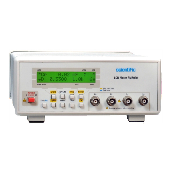
Front Panel Controls AUTO LEVEL BIAS LCR METER 6020 MODEL/AUTO FREQ RANGE AUTO : Push Long Freq Set POWER N/Vs/M Freq L/C/R Range ON/OFF Eq Ckt Save/Rcl Menu Disp Discharge test device before connecting Fig 1 Power : When push button pressed , switches power ON to the instrument. - Page 11 Keyboard : The keyboard is used to select the functions of the instrument and configure different Parameters. Some keys have dual Functions,as simple push and long push. The Secondary function is noted different color on the panel . L / C / R : This button selects the parameter, measuring parameters apart from transformers.
- Page 12 Save/Rcl Push button allows to save the value of parameters in particular memory location selected by you. There are 25 memory locations . For recalling the desired value stored in memory location, pressed the push button long for more than 2 seconds, the display shows memory location. Select the desired memory location by incrementing - decrementing , to view the measured value.
-
Page 13: Operating Instructions
Operating Instructions General Information The logical front panel layout of S 6020 ensures rapid familiarization with the various functions. However, even experienced operators should not neglect to carefully read the following instructions, to avoid any operational errors and to be fully acquainted with the instrument when later in use. -
Page 14: First Time Operation
First Time Operation Switching : Plug the mains cable into the mains socket at the rear of the instrument. Now plug the other end into a suitable mains outlet. To switch ON, press power ON switch . On application of power, the LCD displays range and functions etc . - Page 15 while the resistance series eq ckt represent resistance of coil. Heavy inductors are preferably measured with the parallel Eq ckt this case being domination compared to the series resistance. The low values inductors are themselves represented by the series, their reactance being low. In order to obtain a more accurate result high inductances are analyzed with the lowest rate, while low inductors are analyzed in contrast with the highest.
-
Page 16: Understanding Displayed Parameter
Understanding Displayed Parameters Q Inductance and quality factor : The inductor is displayed on the first line of the LCD. Units of the inductance are H, or μH, mH. Q is the ratio the imaginary part of the impedance and has no unit. The Q value is the same for both types of equivalent circuits (series or parallel). -
Page 17: Measurement Of Transformer Parameters
R + X Strength and Reactance : The resistance is displayed on the first line, reactance on the second line. These two values match respectively to the real and imaginary part of the component are expressed in or M . - Page 18 The following parameters are displayed by successive push on the N / Vs / M for the Characterization of processors. The main parameter N is the report of turns ratio between the primary and the secondary winding. The phase shift primary / secondary and the frequency of testing are listed on the second Line.
-
Page 19: Component Sorting & Binning Function
Component Sorting & Binning Function The instrument allows comparison of components compared to a preset value. The instrument will calculate the deference between the value preprogrammed, which can be displayed in the form of an absolute deviation or percentage. To access the sorting function press Menu. Press the button F2 for the right arrow (N / Vs / M) until sorting option appears. -
Page 20: Display Types
Display Types (DISP Push Button) Users can select three possible display types with successive press of DISP button. The measured value The difference in value in relation to the current value. The symbol will show next to the Measured parameter indicates that the function is active. If the sorting mode is active message PASS FAIL is displayed on the second line depending on the value of the component, the nominal value and the percentage are defined by the user. - Page 21 3- For setting nominal value for sorting , press F2 once again after step 1 discussed above. This will display Value option, press F3 to edit . Press F1( NEXT) for moving cursor,F2 (CHANGE) for changing values at cursor position from 0 to 9 , even units can be changed to m, k, M etc.
-
Page 22: Zero Compensation
Zero Compensation or OPEN / SHORT calibration Zero compensation or open-short calibration function of the instrument can compensate for the parts of the measuring cable in order to compensate for parasitic elements. The model used is the one represented in the figure below. The instrument determines the value of these elements Rss and Lss at a preliminary measure. -
Page 23: Frequency Of Test
Calibration short : maximum series resistance of the cables must be less than 8 while the total impedance should be less than 8 Calibration open : parallel impedance of the cable must be more than 1M . The instrument displays the zero readings after adjustment or near zero value , except for small negligible value ( to be ignored , part of value too small in comparison to the range) if the calibration went well, “Failed”... -
Page 24: Impedance Range
Impedance Range The Instrument has 6 impedance ranges (R1-R6). The range of impedance can be selected manually or can be set to automatic, which is the normal or default mode. Range in use is indicated on left in 2 line with word A or H (Flashing) meaning auto or manual. -
Page 25: Precision & Accuracy
Fig 6 The source resistance of the signal generator test is linked to the range as shown in Table (R SOURCE column). The real test voltage within the leads of Component depend on the range and its impedance as shown in the chart below Precision and Accuracy The accuracy of measurements depends on the basic accuracy which depends on the value of the impedance and frequency, This value is increased by a factor... - Page 26 KL = 1 m /Rm. KH = Rm / 1 G KH is negligible for the resistance less than 50 k KL is negligible resistance for more than 20 Accuracy of Q : Qe = (Ar/100) (1+Q x 2) With Ar accuracy of the resistance calculated above Calculation example : ...
-
Page 27: Basic Accuracy Graph
Accuracy of Capacitor : Accuracy C : Ac = [Ae + (KH+KL) x 100]% Ae: basic Accuracy value in the graph below. For values of Q > 0.1 multiply the value of A by (1 + lQl) KH, KL factors corresponding to the error at the ends of lines KL = 0.16 pF/(cm x f) KH = (cm x f)/160 mF F: Frequency test kHz... - Page 28 Fig 7 Fig 9 S 6020 User Manual...
-
Page 29: Remote Programming
A present value of a particular parameter may be determined by querying the SM6020 for its value. A query is formed by appending a question mark “?” to the command mnemonic and omitting the desired parameter from the command. - Page 30 FREQ (?) {i} The FREQ command sets the drive frequency according to the table below. The FREQ? query returns the drive frequency. Frequency 100 Hz 120 Hz 250 Hz 500 Hz 1 kHz 2.5 kHz 5 kHz 7.8125 kHz 12.5 kHz 15.625 kHz 25 kHz User frequency...
- Page 31 RNGH (?) {i} The RNGH command disables (i=0) and enables (i=1) range hold. When range hold is disabled the SM6020 will autorange. The RNGH? Query returns the range hold status. VOLT (?) {i} The VOLT command sets the drive voltage to 50 mV (i=0) and 500mV (i=1).
- Page 32 The PREL command sets the relative parameter value for deviation and percent deviation measurements to x. This command will return an error if the SM6020 is set to AUTO parameter mode. The units of x are Ohms in R+Q mode, Henrys in L+Q mode, and Farads in C+D mode.
- Page 33 Setup Commands *IDN? The *IDN? Common query returns the SM6020’s device configuration. This string is in the format “REVISION Z.ZZ”. Where “Z.ZZ” is the 3 digit firmware revision number. S 6020 User Manual...
-
Page 34: Maintenance
Maintenance There are no user serviceable part inside 6020 . Your 6020 LCR Meter is thoughtfully engineered for ease of use, accuracy and reliability. The instrument is carefully tested and calibrated using standards traceable to National Laboratories. Take care of your instrument by cleaning the exterior of the instrument regularly with a dusting brush. -
Page 35: Warranty
Warranty Conditions 1. Scientific warrants all its Instruments to be free from defects in material and workmanship when used under normal operating conditions in accordance with the instructions given in the manual for a period of 12(Twelve) months from date of purchase from Scientific or its authorised dealers.
Need help?
Do you have a question about the SM6020 and is the answer not in the manual?
Questions and answers