Table of Contents
Advertisement
Safe Operation Practices • Set-Up • Operation • Maintenance • Service • Troubleshooting • Warranty
OPERATOR'S MANUAL
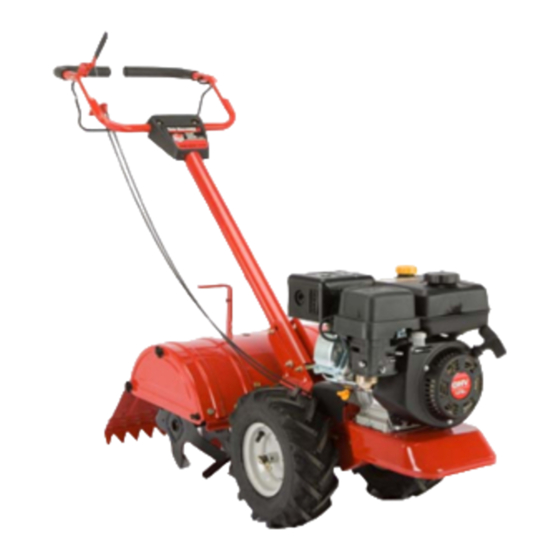
Rear Tine CRT Tiller — 400
WARNING
READ AND FOLLOW ALL SAFETY RULES AND INSTRUCTIONS IN THIS MANUAL
BEFORE ATTEMPTING TO OPERATE THIS MACHINE.
FAILURE TO COMPLY WITH THESE INSTRUCTIONS MAY RESULT IN PERSONAL INJURY.
MTD PRODUCTS LTD., P. P. BOX 1386, KITCHENER, ONTARIO CANADA N2G 4J1
Printed In USA
769-05715A
(2.19.10)
Advertisement
Table of Contents

Related Manuals for MTD Rear Tine CRT Tiller 400


Summary of Contents for MTD Rear Tine CRT Tiller 400
- Page 1 READ AND FOLLOW ALL SAFETY RULES AND INSTRUCTIONS IN THIS MANUAL BEFORE ATTEMPTING TO OPERATE THIS MACHINE. FAILURE TO COMPLY WITH THESE INSTRUCTIONS MAY RESULT IN PERSONAL INJURY. MTD PRODUCTS LTD., P. P. BOX 1386, KITCHENER, ONTARIO CANADA N2G 4J1 Printed In USA 769-05715A...
-
Page 2: Table Of Contents
Choose from the options below: ◊ Visit us on the web at www.mtdcanada.com ◊ Call a Customer Support Representative at (800) 668-1238 ◊ Write us at MTD Products. Ltd., P. O. Box 1386, Kitchener, ON Canada N2G 4J1... -
Page 3: Safe Operation Practices
Important Safe Operation Practices WARNING! This symbol points out important safety instructions which, if not followed, could endanger the personal safety and/or property of yourself and others. Read and follow all instructions in this manual before attempting to operate this machine. Failure to comply with these instructions may result in personal injury. - Page 4 Never store the machine or fuel container inside Use only attachments and accessories approved by the where there is an open flame, spark or pilot light manufacturer. Failure to do so can result in personal injury. as on a water heater, space heater, furnace, clothes If situations occur which are not covered in this manual, use dryer or other gas appliances.
- Page 5 Spark Arrestor WARNING! This machine is equipped with an internal combustion engine and should not be used on or near any unimproved forest-covered, brushcovered or grass-covered land unless the engine’s exhaust system is equipped with a spark arrester meeting applicable local or provincial laws (if any). If a spark arrester is used, it should be maintained in effective working order by the operator.
-
Page 6: Assembly & Set Up
Assembly & Set-Up Contents of Carton • One Tiller • One Operator’s Manual • One Handlebar Assembly • Bottle Oil WARNING! To prevent personal injury or property damage, do not start the engine until all assembly steps are complete and you have read and understand the Safe Operation Practices Section and the Operating Section in this manual. - Page 7 Snap the cable housing clips into the handle Click Pin assembly cable mount as seen here. The red clip (reverse cable) fits into the top position on the handle assembly, while the black clip (forward/clutch cable) feeds into the lower position on the handle assembly.
- Page 8 Transmission/Gear Oil The transmission was filled with gear oil at the factory. However, you should check the gear oil level at this time to make certain it Depth Regulator Lever is correct. NOTE: Do not operate the tiller if the gear oil level is low. Doing so will result in severe damage to the transmission components.
-
Page 9: Controls & Features
Controls and Features Reverse Handle Forward Clutch Bail & Tine Engagement Depth Regulator Handle Height Adjustment Choke Rear Tine Shield Throttle Starter Side Shield Handle Tines Wheel Drive Pin Figure 4-1 WARNING! Read and follow all safety rules and instructions in this manual, including the entire Operation section, before attempting to operate this machine. - Page 10 Reverse Handle Rear Tine Shield The Reverse Handle controls the reverse drive of the wheels and The rear tine shield protects the operator from flying debris tines. while also smoothing out freshly tilled soil. Forward Clutch Bail & Tine Engagement Side Shield The forward clutch bail controls the engagement of the forward The side shield is used to maintain clear even rows and may be...
-
Page 11: Operation
Operation Starting And Stopping WARNING: Before operating your machine, carefully read and understand this manual and all of Pre-Start Checklist its safety, operating and maintenance sections and instructions, along with all of the decals on the With the spark plug wire disconnected from the spark plug, machine. - Page 12 Setting The Depth Put the throttle control lever located on the engine in the “FAST” or “Rabbit” position. Tilling depth is controlled by the depth stake which can be Move the Choke into the Choke position. adjusted to five different settings. Adjust the side shields as you Put one hand on the fuel tank to stabilize the tiller when adjust the depth stake.
- Page 13 Adjusting the Handle Height Tilling Tips & Techniques The handle should be adjusted so that when the tiller is digging Tilling Depth 3-4” into the soil, the handle falls to about waste-high. To adjust WARNING! Before tilling, contact your telephone the handle, simply loosen the handle adjustment crank, move or utilities company and inquire if underground the handle to the desired height and retighten the adjustment...
- Page 14 Choosing Correct Wheel & Tine Speeds • If the garden size will not permit lengthwise and then crosswise tilling, then overlap the first pass by one-half a With experience, you will find the tilling depth and tilling speed tiller width, followed by successive passes at one-quarter combination that is best for your garden.
- Page 15 Terrace Gardening • Position the loading vehicle so that the ramp angle is as flat as possible (the less incline to the ramp, the better). Turn To create a terrace, start at the top of the slope and work the vehicle’s engine off and apply the parking brake. down.
-
Page 16: Maintenance & Adjustment
Maintenance & Adjustments Maintenance Schedule Check Before Every Every Every After first Engine each use 5 Hours 10 Hours 30 Hours 2 hours Manual Check Motor Oil Level Clean Engine Check Drive Belt Tension Check Nuts and Bolts Lubricate Tiller Check Gear Oil Level in Transmission Check Tines for Wear Check Air Pressure in Tires... - Page 17 Lubrication Transmission Gear Oil Check the transmission gear oil after every 30 hours of operation After every 10 operating hours, oil or grease the lubrication or whenever you notice any oil leak. Operating the tiller when points shown in Fig. 6-2 and described below. the transmission is low on oil can result in severe damage.
- Page 18 Off-Season Storage When the tiller won’t be used for an extended period, prepare it for storage as follows: Clean the tiller and engine. Do routine tiller lubrication and check for loose parts and hardware. Refer to the separate engine manual for correct engine storage instructions.
-
Page 19: Service
Service Belt Replacement If the drive belt or reverse belt needs to be replaced, it is best to replace both belts at the same time. Use only a factory- authorized belt as an “over- the-counter” belt may not perform satisfactorily. The procedure requires average mechanical ability and commonly available tools. - Page 20 Remove the hex bolt securing the transmission drive Remove pulley pulley, then remove the pulley along with the two belts. Remove hex bolt with belts See Fig. 8-5. Replace the old belts with the new belts in the same order they were removed.
-
Page 21: Troubleshooting
Troubleshooting Problem Cause Remedy Engine does not start Spark plug wire disconnected. Reconnect wire. Engine Throttle Control Lever incorrectly set. Put lever in START position. Fuel tank empty. Add fuel. Stale gasoline. Drain fuel and add fresh fuel. Dirty air filter. Clean or replace filter (see separate Engine Manual). -
Page 22: Parts List
400 Series Handle & Tine Shield Guidon et protecteur de dents séries 400... - Page 23 400 Series Handle & Tine Shield Guidon et protecteur de dents séries 400 PART N° DE N° DE RÉF PIÈCE DE SCRIP TION DE SCRIP TION 686-0044B End Cover Assembly Couverture latérale 710-0597 Hex Screw 1/4-20 x 1.00 Vis à tête hexagonale 1/4-20 x 1,00 710-0604A Self-tapping Screw 5/16-18 x .625 Vis autotaraudeuse 5/16-18 x 0,625 po...
- Page 24 400 Series Drive System Système d’entraînement séries 400...
- Page 25 400 Series Drive System Système d’entraînement séries 400 PART N° DE N° DE RÉF PIÈCE DE SCRIP TION DE SCRIP TION 734-04232 Comp. Wheel Ass’y 13 x 5 x 6 Ensemble de roue comp. 13 x 5 x 6 714-0143A Klik Pin 1/4 Dia.
- Page 26 400 Series Transmission Assembly Ensemble de transmission séries 400...
- Page 27 400 Series Transmission Assembly Ensemble de transmission séries 400 PART N° DE N° DE RÉF PIÈCE DE SCRIP TION DE SCRIP TION 618-04815A Transmission Assembly Transmission 619-04184A Transmission Housing Carter de transmission 710-3008 Hex Bolt 5/16-18 x .75" Lg. Gr. 5 Boulon hex.
-
Page 28: Warranty
HOW TO OBTAIN SERVICE: Warranty service is available, WITH PROOF OF PURCHASE, through your local authorized service dealer. To locate the dealer in your area contact MTD Products Limited, Kitchener, ON N2G 4J1, or call 1-800-668-1238 or log on to our Web site at www.mtdcanada.com. - Page 29 Notes...
- Page 30 Notes...
Need help?
Do you have a question about the Rear Tine CRT Tiller 400 and is the answer not in the manual?
Questions and answers