Table of Contents
Advertisement
Quick Links
A l l t e s t I n s t r u me n t s , I n c .
5 0 0 C e n t r a l A v e .
F a r mi n g d a l e , N J 0 7 7 2 7
P : ( 7 3 2 ) 9 1 9 - 3 3 3 9
F : ( 7 3 2 ) 9 1 9 - 3 3 3 2
a l l t e s t . n e t
s s a l e s @ a l l t e s t . n e t
T h e t e s t & me a s u r e me n t
e q u i p me n t y o u n e e d a t
t h e p r i c e y o u w a n t .
A l l t e s t c a r r i e s t h e w o r l d ' s l a r g e s t s e l e c t i o n o f
u s e d / r e f u r b i s h e d b e n c h t o p t e s t & me a s u r e me n t
e q u i p me n t a t 5 0 % t h e p r i c e o f n e w .
O O u r e q u i p me n t i s g u a r a n t e e d w o r k i n g , w a r r a n t i e d , a n d
a v a i l a b l e w i t h c e r t i f i e d c a l i b r a t i o n f r o m o u r i n - h o u s e s t a f f
o f t e c h n i c i a n s a n d e n g i n e e r s .
• 1 0 + f u l l t i me t e c h n i c i a n s w i t h o v e r 1 5 0 y e a r s o f
s p e c i a l i z a t i o n
• 9 0 d a y w a r r a n t y & 5 d a y r i g h t o f r e t u r n o n a l l
e q u i p me n t
• • 1 - 3 y e a r w a r r a n t i e s f o r n e w a n d
p r e mi u m- r e f u r b i s h e d e q u i p me n t
• E v e r y u n i t t e s t e d t o O E M s p e c i f i c a t i o n s
• S a t i s f a c t i o n g u a r a n t e e d
Y o u h a v e p l a n s , w e w i l l h e l p y o u a c h i e v e t h e m.
A n y p r o j e c t . A n y b u d g e t .
t
G e t a q u o t e t o d a y !
C C a l l ( 7 3 2 ) 9 1 9 - 3 3 3 9 o r e ma i l s a l e s @a l l t e s t . n e t .
Advertisement
Table of Contents
Troubleshooting

Related Manuals for HP 85097A


Summary of Contents for HP 85097A
- Page 1 T h e t e s t & me a s u r e me n t e q u i p me n t y o u n e e d a t t h e p r i c e y o u w a n t . A l l t e s t I n s t r u me n t s , I n c .
- Page 2 Agilent Test & Measurement website, www.tm.agilent.com. HP References in this Manual This manual may contain references to HP or Hewlett-Packard. Please note that Hewlett-Packard's former test and measurement, semiconductor products and chemical analysis businesses are now part of Agilent Technologies. We have made no changes to this manual copy.
- Page 3 User’s Guide HP 85097A Electronic Calibration System HP Part Number: 85091-90007 Supersedes 85091-90001 Printed in USA July 1999...
- Page 4 Notice The information contained in this document is subject to change without notice. Hewlett-Packard makes no warranty of any kind with regard to this material, including, but not limited to, the implied warranties of merchantability and fitness for a particular purpose.
-
Page 5: Table Of Contents
ECal Module Options and Operating Characteristics ......1-10 HP 85097A PC Interface System Characteristics and Requirements....1-12 Environmental . - Page 6 Ramp-Sweep With an HP 8510B/C ........
- Page 7 HP 85060C Control Unit-Based ECal System ........
-
Page 8: General Information
General Information... - Page 9 General Information The HP 85097A electronic calibration system (ECal) is a precision, single-connection, one-port or two-port calibration technique, that uses fully traceable electronic standards. ECal provides repeatable, accurate measurements, while bringing convenience and simplicity to your calibration routine. ECal replaces the traditional calibration technique that uses mechanical standards.
-
Page 10: About This Manual
General Information About This Manual About This Manual This manual applies to the HP 85097A PC-based ECal system. For operation information about the HP 85060C control unit-based system, refer to Appendix A in this manual, or refer to your HP 85060C manual. -
Page 11: Ecal System
ECal System ECal systems consist of one or more ECal modules, and the HP 85097A PC interface kit. You must supply your own PC equipped with an HP-IB (IEEE-488) interface card. The ECal modules calibrate VNA systems for measurements with 3.5 mm, type-N 50 Ω, 7 mm, type-N 75 Ω, 7-16 and type-F connectors. -
Page 12: Vector Network Analyzer
VNA setups. See Table 1-4 on page 1-10 for more information. Option 001 adds an HP 8509X module for calibrations below 1 GHz. ECal modules cannot be used to calibrate for frequencies outside the NOTE operating frequency range of the VNA being used. - Page 13 General Information ECal System Table 1-1 VNA Models and Supported Firmware Revisions Network Analyzer Firmware Revision HP 8753C 4.13 HP 8753D 6.14 or higher HP 8753E 7.12 or higher HP 8510B 6.54 HP 8510C 7.00 or higher HP 8719C 1.05 HP 8719D 6.14 or higher...
-
Page 14: Pc Interface Unit
It automatically turns the power off when you disconnect an ECal module. If you have an HP 8506XA module, a jumper can be installed to make it NOTE compatible with the PC interface unit. Contact the nearest HP sales or service office for information about returning your module for this... -
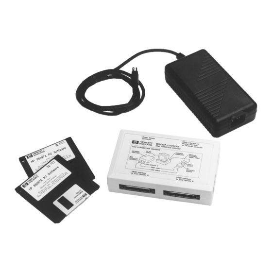
Page 15: Ecal Power Supply Unit
General Information ECal System ECal Power Supply Unit The ECal power supply unit is used to provide a 24 VDC supply to the PC interface unit. It also allows for the supply of power to the ECal modules. To prevent electrical shock, disconnect from mains before WARNING cleaning. -
Page 16: Ieee-488 Interface
General Information ECal System Listed below are the file names and versions of the ECal software used in the HP 85097A ECal system. Table 1-3 Software Software Version Ecal.exe 01.008 EcalSPI.dll 01.002 ECal.dll 01.08 IEEE-488 Interface The customer-supplied IEEE-488 interface card allows the PC software to control the VNA during the calibration process. -
Page 17: Ecal Module Options And Operating Characteristics
Table 1-4 ECal Modules and Options Available Module Model Connector Frequency Range Options Available Number Type HP 85091A 7 mm 1BN, 1BP, 910, UK6 30 kHz to 6 GHz Type-N (50 Ω) HP 85092A 00M, 00F, 00A, 1BN, 1BP, 910, UK6... - Page 18 Additional set of ECal manuals Commercial calibration certificate with measurement data 1. RF ECal modules are specified to operate from 300 kHz, with typical performance down to 30 kHz. 2. Only available on HP 85062B and HP 85064B. Chapter 1 1-11...
-
Page 19: Hp 85097A Pc Interface System Characteristics And Requirements
General Information HP 85097A PC Interface System Characteristics and Requirements HP 85097A PC Interface System Characteristics and Requirements This product is designed for use in INSTALLATION CATEGORY II and NOTE POLLUTION DEGREE 2, per IEC 1010 and 664 respectively. Enclosure protection according to IEC 529, IP Code 2 0. -
Page 20: Electrical
General Information HP 85097A PC Interface System Characteristics and Requirements Electrical The power supply has auto-ranging line voltage input; be sure the CAUTION supply voltage is within the specified range. Table 1-7 Electrical and Mechanical Characteristics Characteristics Limits Power Requirements:... -
Page 21: Preparation For Use
General Information Preparation for Use Preparation for Use Installation Checklist Check the following conditions before plugging your PC interface module into the ac power line: Check the ac power line voltage to verify compatibility requirements (refer to Table 1-7 on page 1-13 for power requirements). -
Page 22: Warranty
Warranty service for products installed by HP and certain other products designated by HP will be performed at Buyer’s facility at no charge within HP service travel areas. Outside HP service travel areas, warranty service will be performed at Buyer’s facility only upon HP’s... -
Page 23: Assistance
General Information Warranty EXCLUSIVE REMEDIES. THE REMEDIES PROVIDED HEREIN ARE BUYER’S SOLE AND EXCLUSIVE REMEDIES. HP SHALL NOT BE LIABLE FOR ANY DIRECT, INDIRECT, SPECIAL, INCIDENTAL, OR CONSEQUENTIAL DAMAGES, WHETHER BASED ON CONTRACT, TORT, OR ANY OTHER LEGAL THEORY. Assistance Product maintenance agreements and other customer assistance agreements are available for Hewlett-Packard products. -
Page 24: Safety And Regulatory Information
General Information Safety and Regulatory Information Safety and Regulatory Information Review this product and related documentation to familiarize yourself with safety markings and instructions before you operate the instrument. This product has been designed and tested in accordance with international standards. The WARNING notice denotes a hazard. -
Page 25: Instrument Markings
General Information Safety and Regulatory Information Instrument Markings When you see this symbol on your instrument, you should refer to the instrument’s instruction manual for important information. This symbol indicates hazardous voltages. The laser radiation symbol is marked on products that have a laser output. -
Page 26: Before Applying Power
General Information Safety and Regulatory Information This product has been designed and tested in accordance with IEC NOTE Publication 1010, Safety Requirements for Electronic Measuring Apparatus, and has been supplied in a safe condition. The instruction documentation contains information and warnings which must be followed by the user to ensure safe operation and to maintain the product in a safe condition. -
Page 27: Compliance Notices
General Information Safety and Regulatory Information Compliance Notices Compliance With German Noise Requirements This is to declare that this instrument is in conformance with the German Regulation on Noise Declaration for Machines (Laermangabe nach der Maschinenlaermrerordnung -3.GSGV Deutschand). Acoustic Noise Emission/Geraeuschemission LpA <70 dB LpA <70 dB Operator position... - Page 28 General Information Safety and Regulatory Information Chapter 1 1-21...
- Page 29 Operating an ECal System...
-
Page 30: Operating An Ecal System General Information
VNA. The data is then used to compute actual device response by eliminating systematic error contributions. Compatible Vector Network Analyzers The ECal system is designed to work with a variety of HP vector network analyzers. Compatible models are listed in Table 1-1 on page 1-6. -
Page 31: Electrostatic Discharge (Esd)
Operating an ECal System Electrostatic Discharge (ESD) Electrostatic Discharge (ESD) Protecting from ESD Damage Protection against electrostatic discharge (ESD) is essential while cleaning, inspecting, or making any connections around static sensitive circuits (such as those found in VNA port connectors and ECal modules). -
Page 32: Esd Guidelines
This discharges static electricity and protects test equipment circuitry. Refer to the Electronic Calibration Module Reference Guide (HP part number 85091-90008) for the HP part numbers of ESD supplies. -
Page 33: Setting Up An Ecal System
Operating an ECal System Setting Up an ECal System Setting Up an ECal System Figure 2-2 shows the set up for a VNA with the PC interface unit, and an ECal module. Figure 2-2 System Diagram Using PC Interface Unit Chapter 2... -
Page 34: Connecting And Disconnecting Modules
To learn about correctly connecting and disconnecting calibration modules to the VNA, refer to the Electronic Calibration Module Reference Guide (HP part number 85091-90008). Since the PC interface unit is capable of controlling the power supplied NOTE to a module, the module may be connected/disconnected while power is supplied to the PC interface unit. -
Page 35: Installing And Using The Software
• An available parallel port. HP-IB Card and Software • Check that the interface card and software have been installed in the PC and are operational. Refer to your HP-IB (IEEE-488) documentation for installation instructions. • Use any of the following interface cards: —... -
Page 36: Installation And System Setup
Operating an ECal System Installing and Using the Software Installation and System Setup ECal Software Installation 1. Turn on the PC and wait until the Windows environment presents itself on the screen. 2. Insert the PC interface software disk into the PC disk drive. 3. - Page 37 Operating an ECal System Installing and Using the Software 2. From the Windows environment, select the following keys to start the ECal program. a. Select (located in the lower left-hand corner of the display). Start b. Select Programs c. Locate the ECal program name and select it. d.
-
Page 38: Ecal Pc Graphical User Interface (Gui)
Operating an ECal System ECal PC Graphical User Interface (GUI) ECal PC Graphical User Interface (GUI) The following figures show you the dialog boxes that you will see on your PC after the ECal software has been installed. Figure 2-4 The ECal Setup Dialog Box Calibration Procedure 1. - Page 39 3. Complete the calibration process using the softkey menus displayed on the VNA. See Figure 2-8 for VNA menu To release the ECal software’s control of the VNA, press any HP 87XX NOTE front-panel key. For an HP 8510X, press any of its main menu keys. Chapter 2...
- Page 40 Operating an ECal System ECal PC Graphical User Interface (GUI) Figure 2-7 ECal Menus During the Calibration Routine Use the network analyzer softkeys to select the calibration type you need, and to complete your calibration procedures. If you really want to stop, select Yes from this screen.
-
Page 41: Calibration Menus On Vnas
VNA configuration settings (such as averages), with the exception of isolation calibrations. Isolation calibrations use the number of averages set in the ECal configuration menu. Figure 2-8 Example Calibration Menu from an HP 8510 VNA Chapter 2 2-13... -
Page 42: Vna Main Menu Keys
ISOLATION AVERAGES the VNA keypad. Values from 1 to 4096 are valid for the HP 8510 VNA. Values from 1 to 999 are valid for the HP 87xx VNA series. The speed of the calibration is determined by the number of isolation NOTE averages. -
Page 43: Ecal Menu
This is the only calibration selection that is valid for the following NOTE analyzers: HP 8719ET, HP 8720ET, HP 8722ET, and HP 8753ET. These analyzers only make transmission and reflection measurements; selecting “S11 PORT” is equivalent to selecting “Reflection 1-Port” on these analyzers. - Page 44 Operating an ECal System VNA Main Menu Keys ADAPTER 2-PORT This calibration achieves high accuracy magnitude and phase measurements (including isolation) of non-insertable two-port configurations. This calibration is similar to the full 2-port calibration. The difference is in the optional metrology-grade adapters used to provide a full 2-port calibration for devices with same-sex connectors.
-
Page 45: Module Selection Menu
Operating an ECal System VNA Main Menu Keys Module Selection Menu The “Module Selection” menu appears after choosing the calibration type from the ECAL menu. 4. Select the ECal module according to connector type and the frequency range of the DUT. 5. -
Page 46: Service Menu
Operating an ECal System VNA Main Menu Keys currently acquired data. • DATA&MEM shows both the pre-measured and current data for on-screen visual comparison. 4. Select to return to the “Confidence Check” menu. DONE CHECK 5. Select to return to the “Calibrate Configure” menu. RETURN 6. -
Page 47: Calibrations
VNA used have a direct effect on these factors. For information about gaging and making connections with ECal modules, refer to the Electronic Calibration Module Reference Guide (HP part number 85091-90008). For information about specific VNAs, refer to the appropriate VNA user's guide. -
Page 48: Ramp-Sweep With An Hp 8510B/C
Operating an ECal System Calibrations Ramp-Sweep With an HP 8510B/C When using HP 8510 series VNAs, calibrations cannot be performed in the ramp-sweep mode. If ramp sweep is required during measurements, calibrate the system in step mode, then perform measurements in ramp sweep mode. -
Page 49: Calibrating Across Overlapping Frequency Ranges
Calibration kits may contain two modules (an RF module and a microwave module) that overlap in frequency coverage. For example, the HP 85060B Option 001 contains an RF (30 kHz to 6 GHz) module and a microwave (1 to 18 GHz) module. In the overlapping frequency range, the module specifications may vary. -
Page 50: Performing Ecal Calibrations
3. Connect the ECal module(s) to the PC interface and allow the module(s) to warm up for at least 10 minutes. Sweep-mode calibrations are possible on the HP 8720 series VNAs. NOTE However, the calibration will be degraded relative to step-mode calibration. -
Page 51: Performing An S11 1-Port Calibration
The type-F and type-N 75 Ω connector module kits do not include a NOTE torque wrench. To order a torque wrench, contact the nearest HP sales or service office. A12 mm 170 N-cm (15 in-lb) torque wrench can be used with type-F modules. -
Page 52: Performing An S22 1-Port Calibration
The type-F and type-N 75 Ω connector module kits do not include a NOTE torque wrench. To order a torque wrench, contact the nearest HP sales or service office. A 12 mm 170 N-cm (15 in-lb) torque wrench can be used with type-F modules. -
Page 53: Adapter Calibrations
Operating an ECal System Adapter Calibrations Adapter Calibrations Adapter 2-Port Calibrations When using multiple modules for adapter calibrations, you must measure all ECal modules for each step before using the adapters. Adapter 2-Port Calibrations are only for use with Option 00A. NOTE If the VNA is set such that the frequency spacing between any two measurement points is less than 50 MHz or if less than four... - Page 54 Operating an ECal System Adapter Calibrations in the VNA menu. 6. Repeat as necessary using all modules required to cover the desired frequency range. 7. Press to continue. NEXT MENU Figure 2-9 Adapter Removal Calibration, Step 1 Connect the adapter 1.
- Page 55 Operating an ECal System Adapter Calibrations Figure 2-10 Adapter Removal Calibration, Step 2 Save the calibration data 1. Press in the network analyzer menu. SAVE ADAPTER 2-PORT 2. Select a storage register or Cal Set from the VNA “Save Register” menu (depending on the type of VNA you are using).
-
Page 56: Performing An Omit Isol Adp 2-Port Calibration
Operating an ECal System Adapter Calibrations Performing an OMIT ISOL ADP 2-PORT Calibration 1. Connect the module to Port 2 of the VNA (see Figure 2-9 on page 2-26). If the VNA is set such that the frequency spacing between any two NOTE measurement points is less than 50 MHz or if less than four measurement points are selected, make certain an adapter-delay value... - Page 57 Operating an ECal System Adapter Calibrations Save the calibration data 1. Press in the network analyzer menu. SAVE OMIT ISOL ADP 2-PORT 2. Select a storage register or Cal Set from the VNA “Save Register” menu (depending on the type of VNA you are using). 3.
-
Page 58: Calibration-Data Confidence Checking
VNA parameters (with the exception of the data in memory before the confidence check was invoked). To release the ECal software’s control of the VNA, press any HP 87XX NOTE front-panel key. For an HP 8510X, press any of its main menu keys. -
Page 59: Performing The Confidence Check
DONE CHECK selected, noncritical scales, parameters and display options may remain active. To release the ECal software’s control, press any HP 87XX front-panel NOTE key. For an HP 8510X, press any of its main menu keys. Chapter 2 2-31... - Page 60 Software Programming Interface...
-
Page 61: Software Programming Interface General Information
Software Programming Interface General Information General Information This chapter assumes that the reader has some programming NOTE experience. The ECal software programming interface (SPI) is programmer’s tool for adding automated VNA calibration capability within an application. The SPI is a self-registering, OLE 2.0 compliant, in-process DLL server. It can be accessed by any programming language or environment that supports OLE. -
Page 62: Ecal Spi Functions
VNA prior to initiating a calibration. Once the SPI has started a calibration, no other application should try to send commands to the VNA or any other instruments on the HP-IB bus. ECal SPI Format Each ECal command description (provided in “ECal SPI Function... -
Page 63: Ecal Software Structure
Software Programming Interface ECal Software Structure ECal Software Structure Application programmers can use the SPI to interface with the ECal software. The SPI is the second of three layers as shown by the dotted lines in Figure 3-1. Figure 3-1 ECal SPI Software Architecture The following table shows the programming versions supported by ECal. -
Page 64: Starting Up Software
Software Programming Interface ECal Software Structure Starting Up Software Confirm that the Ecal SPI.dll and other software components have been correctly installed before trying to program with the SPI by successfully running the ECal GUI Ecal.exe. Before sending other commands to the ECal hardware via the SPI, you must initialize the ECal system by sending a CONFIG command. -
Page 65: Programming Examples
ECal Start button: 1. Starts the calibration thread. 2. Tells the SPI what type of HP-IB (IEEE-488) card is in use, selects the code of the card, the VNA address, and the number of the parallel port connected to the ECal module (use CONFIG). -
Page 66: Microsoft Visual C
Please note that <root ecal>\examples\cpp has several hard-coded NOTE values, such as the type and logical number of the HP-IB (IEEE-488) card, VNA address, and so forth. You need to recompile the application for your specific setup to have it work for your application. -
Page 67: Troubleshooting Example C++ File
Software Programming Interface Microsoft Visual C++ Troubleshooting Example C++ File If the C++ example file doesn’t compile, input the following to correct the compile problem: ecalspi.h file fix: // Machine generated IDispatch wrapper class (es) created with ClassWizard //////////////////////////////////////////////////////////////// _clsECalSPI wrapper class class _clsECalSPI : public COLeDispatchDriver public: _clsECalSPI () {}... -
Page 68: Ecalspi.cpp File Fix
Software Programming Interface Microsoft Visual C++ long SENS_CORR_COLL_DONE (); long SENS_CORR_COLL_NEXT (); long SENS_CORR_COLL_PRIOR (); long SENS_CORR_COLL_RES (); long SENS_CORR_COLL_VIEW(BSTR* strView); long SYST_ERR(BSTR* strErrorNumAndMessage); long CMD_IDN(BSTR* strReturn); ecalspi.cpp file fix : // Machine generated IDispatch wrapper class (es) created with ClassWizard #include “stdafx.h”... - Page 69 Software Programming Interface Microsoft Visual C++ long result; static BYTE parms[] = VTS_PI2 VTS_PI2 VTS_PI2; InvokeHelper(0x60030001, DISPATCH_METHOD, VT_I4, (void*)&result, parms, BoardType, BoardNumber, VNAAddress, PrinterPort); return result; long _clsECalSPI::ECAL_DELAY (double* AdapterDelayInSeconds, short* MeasureDelay) long result; static BYTE parms[] = VTS_Pr8 VTS_PI2; InvokeHelper(0x60030002, DISPATCH_METHOD, VT_I4, (void*)&result, parms, AdapterDelayInSeconds, MeasureDelay);...
- Page 70 Software Programming Interface Microsoft Visual C++ long _clsECalSPI::ECAL_IAV(BSTR* strAvg, BSTR* strReturn) long result; static BYTE parms[] = VTS_PBSTR VTS_PBSTR; InvokeHelper(0x60030005, DISPATCH_METHOD, VT_I4, (void*)&result, parms, strAvg, strReturn); return result; long _clsECalSPI::ECAL_ABORT() long result; InvokeHelper(0x60030006, DISPATCH_METHOD, VT_I4, (void*)&result, NULL); return result; long _clsECalSPI::ECAL_CLEAN() long result;...
- Page 71 Software Programming Interface Microsoft Visual C++ long result; static BYTE parms[] = VTS_PBSTR; InvokeHelper(0x60030009, DISPATCH_METHOD, VT_I4, (void*)&result, parms, strParameter); return result; long _clsECalSPI::SENS_CORR_COLL_ACQ(BSTR* strModule) long result; static BYTE parms[] = VTS_PBSTR; InvokeHelper(0x6003000a, DISPATCH_METHOD, VT_I4, (void*)&result, parms, strModule); return result; long _clsECalSPI::SENS_CORR_COLL_SAVE(BSTR* strCalSet) long result;...
- Page 72 Software Programming Interface Microsoft Visual C++ long _clsECalSPI::SENS_CORR_COLL_PRIOR() long result; InvokeHelper(0x6003000e, DISPATCH_METHOD, VT_I4, (void*)&result, NULL); return result; long _clsECalSPI::SENS_CORR_COLL_RES() long result; InvokeHelper(0x6003000f, DISPATCH_METHOD, VT_I4, (void*)&result, NULL); return result; long _clsECalSPI::SENS_CORR_COLL_VIEW(BSTR* strView) long result; static BYTE parms[] = VTS_PBSTR; InvokeHelper(0x60030010, DISPATCH_METHOD, VT_I4, (void*)&result, parms, strView);...
- Page 73 Software Programming Interface Microsoft Visual C++ VTS_PBSTR; InvokeHelper(0x60030012, DISPATCH_METHOD, VT_I4, (void*)&result, parms, strReturn); return result; When you have completed inputting the program information, your C++ example files will compile. 3-14 Chapter 3...
-
Page 74: Hp-Vee And Labview
Software Programming Interface HP-VEE and LabVIEW HP-VEE and LabVIEW Standard SPI (StdSpi.dll) This section describes the standard SPI used by HP-VEE and LabVIEW. A translation layer is included that allows the graphical programming languages used by Hewlett-Packard’s VEE and National Instrument’s LabVIEW to connect to OLE objects. -
Page 75: Hp Vee Example
A prototype for each function exported from the StdSpi.dll can be found in the file <root ecal>/vee_spi.h. This file is used by HP VEE, and can be used by C or other compilers as a header file if you need to access the SPI via DLL exports rather than through OLE. -
Page 76: Labview Example
Software Programming Interface HP-VEE and LabVIEW When using the National Instruments card, use the GPIB-32.DLL and NOTE Nat.h to directly control the VNA. LabVIEW Example This section describes how to interface between the graphical programming environment, LabVIEW, and the ECal system. -
Page 77: Ecal Spi Function Reference
Software Programming Interface ECal SPI Function Reference ECal SPI Function Reference This section describes the function commands available via the SPI. Function commands are listed in alphabetical order. Function return values indicate successful execution of the function. CAUTION They do indicate errors in the format of the pass parameters in the case of a –1, and installation problems when you get a –2. -
Page 78: Config
CONFIG Purpose Configures the ECal system by setting values for the: • type of HP-IB card in use in the host computer. • select code of the HP-IB card. • HP-IB address of the VNA. • number of the parallel port that is connected. -
Page 79: Disp_Menu
Software Programming Interface ECal SPI Function Reference DISP_MENU Purpose To display an ECal menu on the VNA from the list of available menus. DISP_MENU Function Format Options C++ (ECalSPI.dll) long DISP_MENU (BSTR* strMenu); Visual Basic CALL DISP_MENU (strMenu As String) or (ECalSPI.dll) status&=DISP_MENU (strMenu As String) VEE (StdSPI.dll) -
Page 80: Ecal_Abort
Software Programming Interface ECal SPI Function Reference ECAL_ABORT Purpose This command is used in a multi-threaded application to abort a calibration in progress in another thread. For example, in the ECal.exe application provided, initiates the Start application in one thread, then opens a window with the button in Abort another thread. -
Page 81: Ecal_Clean
Software Programming Interface ECal SPI Function Reference ECAL_CLEAN Purpose Unloads the ECal DLLs and frees up the memory used during a calibration. It has no effect on the calibration itself. It is intended to allow an application to regain some PC resources after a calibration. This function should always be called after an application uses the SPI and before the application exits. -
Page 82: Ecal_Delay
Software Programming Interface ECal SPI Function Reference ECAL_DELAY Purpose Sets the adapter electrical delay value for an adapter removal calibration, or specifies whether the software should try to measure the delay instead. The software can measure the delay if there are at least 4 frequency ≥... -
Page 83: Ecal_Fint
Software Programming Interface ECal SPI Function Reference ECAL_FINT Purpose Turns frequency interpolation on or off. • With frequency interpolation on, any frequencies within the span of the characterized ECal module can be measured. • With frequency interpolation off, only those frequencies that correspond to the actual characterization frequencies of the ECal module are allowed. -
Page 84: Ecal_Iav
Software Programming Interface ECal SPI Function Reference ECAL_IAV Purpose Allows the ECal system to override the averaging value specified in the VNA setup for isolation calibrations. Isolation calibrations typically require significantly higher than normal averaging. Use ECAL_IAV to pass a value to the VNA indicating the desired number of averages. -
Page 85: Sens_Corr_Coll_Acq
Software Programming Interface ECal SPI Function Reference SENS_CORR_COLL_ACQ Purpose Initiates the measurement of a specific ECal module to acquire calibration error coefficients. Before initiating this command, call the functions CONFIG and NOTE SENS_CORR_COLL_METH, otherwise this command functions improperly. SENS_CORR_COLL_ACQ Function Format Options long SENS_CORR _COLL_ACQ BSTR* strModule);... -
Page 86: Sens_Corr_Coll_Done
Software Programming Interface ECal SPI Function Reference SENS_CORR_COLL_DONE Purpose Indicates the completion of a confidence check, sets the ECal module to its idle state, and restores the VNA display. SENS_CORR_COLL_DONE Function Format Options C++ (ECalSPI.dll) long SENS_CORR_COLL_DONE( ); Visual Basic CALL SENS_CORR_COLL_DONE or (ECalSPI.dll) status&=SENS_CORR_DONE... - Page 87 Software Programming Interface ECal SPI Function Reference Input strMethod Calibration Types ADAP Adapter 2-port calibration. Adapter 2-port calibration is a two-step process for performing noninsertable calibrations using an insertable ECal module with an adapter. 1. Use SENS_CORR_COLL_NEXT to advance from step one to step two.
-
Page 88: Sens_Corr_Coll_Next
Software Programming Interface ECal SPI Function Reference SENS_CORR_COLL_NEXT Purpose Used to progress from step one to step two for an adapter calibration. All step one measurements must be completed before issuing the function SENS_CORR_COLL_NEXT, otherwise errors result. See ADAP under SENS_CORR_COLL_METH for a description of the steps. SENS_CORR_COLL_NEXT Function Format Options C++ (ECalSPI.dll) long SENS_CORR_COLL_NEXT ( );... -
Page 89: Sens_Corr_Coll_Prior
Software Programming Interface ECal SPI Function Reference SENS_CORR_COLL_PRIOR Purpose Used to return from step two to step one of an adapter calibration. Any completed step-one measurements are lost. SENS_CORR_COLL_PRIOR Function Format Options C++ (ECalSPI.dll) long SENS_CORR_COLL_PRIOR ( ); Visual Basic CALL SENS_CORR_COLL_PRIOR or (ECalSPI.dll) status&=SENS_CORR_COLL_PRIOR... -
Page 90: Sens_Corr_Coll_Save
Software Programming Interface ECal SPI Function Reference SENS_CORR_COLL_SAVE Purpose Ends the calibration process and loads the coefficients into the VNA. SENS_CORR_COLL_SAVE Function Format Options long SENS_CORR_COLL_SAVE (BSTR* strCalSet); (ECalSPI.dll) Visual Basic CALL SENS_CORR_COLL_SAVE (strCalSet As String) or (ECalSPI.dll) status&=SENS_CORR_COLL_SAVE (strCalSet As String) VEE (StdSPI.dll) long Sens_Corr_Coll_Save(unsigned char* strCalSet);... -
Page 91: Spi_Version
Software Programming Interface ECal SPI Function Reference SPI_VERSION Purpose Returns the version number of the SPI. SPI_VERSION Function Format Options C++ (ECalSPI.dll) void SPI_VERSION (BSTR* version); Visual Basic CALL SPI_VERSION (version As String) (ECalSPI.dll) VEE (StdSPI.dll) void Spi_Version (unsigned char* version); LabVIEW (StdSPI.dll) void Spi_Version (unsigned char* version);... -
Page 92: Syst_Err
Software Programming Interface ECal SPI Function Reference SYST_ERR Purpose Returns the error number and message associated with the latest action of the ECal system. ECal software maintains a three-error deep queue in a first-in-first-out (FIFO) configuration. If more than three errors occur between readings, the most recent errors are lost, and the last error message is replaced with the message QUEUE OVERFLOW. - Page 93 Recertifying ECal Kits...
-
Page 94: Recertifying Ecal Kits General Information
Recertifying ECal Kits General Information General Information Recertification of your calibration kit can only be performed at a Hewlett-Packard authorized service center, (see “Service and Support” on page 5-4). The equipment and calibration standards required to certify the specification limits of the devices in this kit have been specially manufactured, and are not commercially available. -
Page 95: Recertification
Recertifying ECal Kits Recertification Recertification What Recertification Provides Recertified kits include the following: • A new calibration sticker affixed to the case • A “Certificate of Calibration” • A list of NIST (United States National Institute of Standards and Technology) traceable numbers •... - Page 96 Recertifying ECal Kits Recertification How Hewlett-Packard Verifies Kit Devices Hewlett-Packard verifies the specifications of these devices as follows: 1. Residual microwave error terms of the test system are verified using precision airlines and shorts, or low frequency resistance. The low-frequency resistance is traceable to the United States National Institute of Standards and Technology (NIST).
- Page 97 Troubleshooting...
-
Page 98: Troubleshooting General Information
Figure 5-1 on page 5-3. Returning a Kit or Device to HP If your calibration kit or device requires service, contact the Hewlett-Packard office nearest you for information about where to send If you are returning the product to Hewlett-Packard for service, please include the following information (attached to the product if possible): •... - Page 99 Troubleshooting General Information Figure 5-1 Troubleshooting Flowchart Chapter 5...
-
Page 100: Service And Support
Contact the nearest HP service office. You can find a list of HP Service Centers on the web at http://www.hp.com/go/tmdir. If you do not have access to the Internet, one of these HP centers can direct you to your nearest HP representative: Chapter 5... - Page 101 Troubleshooting Service and Support Hewlett-Packard Sales and Service Offices UNITED STATES Instrument Support Center Hewlett-Packard Company (800) 403-0801 EUROPEAN FIELD OPERATIONS Headquarters France Germany Hewlett-Packard S.A. Hewlett-Packard France Hewlett-Packard GmbH 150, Route du Nant-d’Avril 1 Avenue Du Canada Hewlett-Packard Strasse 1217 Meyrin 2/ Geneva Zone D’Activite De 61352 Bad Homburg v.d.H...
-
Page 102: Hp 85060C Information
HP 85060C Information... -
Page 103: Hp 85060C Control Unit-Based Ecal System
HP 85060C Control Unit-Based ECal System HP 85060C Control Unit-Based ECal System This appendix is for use with the HP 85060C control unit. The control unit based ECal system provides one module control method for electronic calibration of VNAs. It houses a central processing unit with built-in firmware and controls the entire calibration process from either... -
Page 104: Characteristics And Specifications
HP 85060C Information Characteristics and Specifications Characteristics and Specifications Electrical and Mechanical Table A-2 HP 85060C Electrical and Mechanical Characteristics Characteristics Limits Power Requirements Line Voltage 90 to 250 Vac Line Frequency 47 to 63 Hz Power Dissipation 200 VA Maximum... - Page 105 2-13 ECal menus 2-13 recertification software verification of devices system where to send a kit turn-on procedure returning a device or kit to HP ECal modules electrostatic discharge error queue service menu 2-18 setting calibration parameters general information 2-13 software...