Advertisement
Quick Links
Disclaimer
Thank you for purchasing GYEMS RMD-L series servo motor system. Please read this statement carefully before use.
Once used, it is considered as acceptance and acceptance of the entire contents of this statement. Please strictly follow
the manual, product description and related laws, regulations, policies and guidelines to install and use the product. In
the process of using the product, the user is committed to being responsible for his or her actions and all consequences
arising therefrom. GYEMS will not be liable for any loss caused by improper use, installation or modification by the user.
GYEMS is a trademark of Guangyu Electromechanical (Shanghai) Co., Ltd. and its affiliates. Product names, brands, etc.
appearing in this document are trademarks or registered trademarks of their respective companies. This product and
manual are copyrighted by GYEMS. Reproduction may not be allowed in any form without permission. The final
interpretation of the disclaimer is owned by GYEMS .
Introduction
The RMD-L servo motor system used a 32-bit high-performance MCU、High bandwidth op amp 、Low internal
resistance flat MOSFET and combined with an optimized version of the FOC control technology, equipped with a high-
performance brushless motor of the DM series, designed for high-precision, high-response, high-torque applications.
The integrated design of the motor and the driver facilitates ,easily apply for system integration. The driver integrates
a high-precision absolute encoder with an easy-to-use closed-loop control algorithm that greatly improves the accuracy
of position ,speed feedback and torque output.
Electrical driver parameter
1.
Input voltage
Normal current
Maxium current
PWM Frequency
Torque loop control
frequency
Torque loop control
bandwidth
Speed loop control
frequency
Position loop control
frequency
Encoder
Bus type
Motor electrical parameters
2.
Check RMD motor data sheet to get detail motor information
Driver interface
3.
RMD-L servo motor manual
DRC06-S6
7.4V~24V
DRC10-S6
7.4V~36V
DRC06-S6
6A
DRC10-S6
10A
DRC06-S6
8A (10s)
DRC10-S6
15A (10s)
24KHz
24KHz
0.4KHz~2.8KHz(Depending on differ motor and torque)
8KHz
8KHz
14bit
RS485(Non-isolation)
V1.2
Advertisement

Summary of Contents for Gyems RMD-L Series
- Page 1 GYEMS will not be liable for any loss caused by improper use, installation or modification by the user.
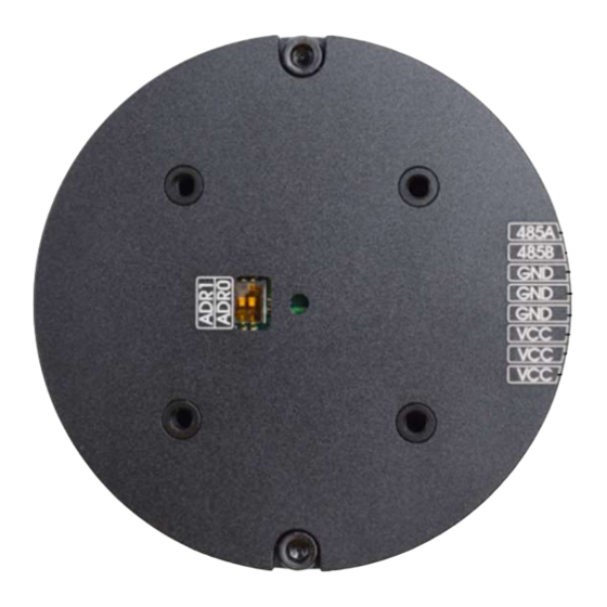
- Page 2 Interface Instruction Negative power supply 485B RS485-B 485A RS485-A Positive power supply Bus feature Bus interface chip:MAX485 Baud rate:9600, 19200, 57600, 115200(default) Data bit:8 Parity bit:None Spot bit:1 Setting PC connection The motor drive and the host computer can be connected via USB to RS485 module. The default baud rate is 115200.
- Page 3 Driver ID:Set the ID number of the driver. When set to 0, the ID is selected by the dial switch, and the corresponding relationship between the two is as follows: Switch 1 Switch 2 Switch 3 Driver Baudrate:Set the baud rate of the drive. Note that the new baud rate needs to be powered back on ...
- Page 4 Current:Torque loop control parameters. Kp and Ki modify the PI parameter of the torque loop,Max Power is used to limit the ouput power to motor Note: 1. Acceleration option does not take effect in the current version of the drive, the actual acceleration of the motor depends on the PI parameters, motor load and drive voltage.
- Page 5 button, the motor will rotate back and forth to perform calibration. After the calibration is completed, the parameters will be automatically saved to the drive. Motor Zero Position:After clicking the Set button, the drive will save the current position as the starting ...
- Page 6 Data description Data length Frame Head byte Frame header recognition,0x3E command Command byte ID byte 1~32 Data length byte Description of Data length 0~60 Frame header Header check sum check byte Frame data 0~60 data stream attached to the data command Data check byte 0 or 1...
- Page 7 recovery ), total command length: 5byte Instruction Memo Head byte 0x3E Command byte 0x88 ID byte 0x01~0x20 #1~#32 Data length 0x00 Head check byte 1~4 byte check sum Eg, the host sends motor running command to 1# driver as follows (HEX) 3E 88 01 00 C7 Zero Position command, set current motor position as zero position, total length of command is 5byte ...
- Page 8 Data check byte 6~7 byte check sum Eg: the data that the 1# driver replies after receiving the command to read the encoder ,as follows (HEX) 3E 90 01 02 D1 CF 0F DE Torque closed-loop control command, which contains a control parameter (motor torque parameter), total ...
- Page 9 Command byte 0xA2 ID byte 0x01~0x20 #1~#32 Data length byte 0x04 Head check byte 1~4byte check sum Motor speed low =*(int8_t *)(&speed) The motor speed represents the byte angular velocity of the motor, which is 32bit shaped data. The Motor speed =*((int8_t *)(&speed)+1) actual speed ratio...
- Page 10 Command byte 0xA3 ID byte 0x01~0x20 #1~#32 Data length byte 0x08 Head check byte 1~4byte check sum Motor position low =*(int8_t *)(&angle) The motor angle represents the byte angle of rotation of the motor, which is 64bit shaped data. The Motor position =*((int8_t *)(&angle)+1) actual...
- Page 11 Head byte 0x3E Command byte 0xA4 ID byte 0x01~0x20 #1~#32 Data length byte 0x08 Head check byte 1~4 byte check sum Motor position low =*(int8_t *)(&angle) The motor speed represents the byte angular velocity of the motor, which is 32bit shaped data. The Motor position =*((int8_t *)(&angle)+1) actual...
- Page 12 Eg: Drive reply after receiving the position closed loop control data, as follows (HEX): 3E A4 01 02 E5 E8 03 EB Position closed loop control 3, the command contains two control parameters, respectively defining the direction of rotation of the motor and the target position (single turn angle value), the maximum speed of motor rotation in this mode is determined by the Max Speed in the set value, the command Total length: 10byte Instruction Memo...
- Page 13 Data check byte 6~7byte check sum Eg: Drive reply after receiving the position closed loop control data, as follows (HEX): 3E A5 01 02 E6 00 0A 0A Position closed-loop control 4, the command contains three control parameters, respectively defining the ...
- Page 14 Head check byte 1~4byte check sum Encoder data low =*(int8_t *)(&encoder) The encoder data is 16bit shaped byte data, and the data range is related to the encoder accuracy, Encoder data high =*((int8_t *)(&encoder)+1) which is generally 0~16383 byte (14bit). Data check byte 6~7byte check sum Eg: Drive reply after receiving the position closed loop control data, as follows (HEX):...
- Page 15 Products application: Guangyu Electric Co.,limited www.gyems.cn 0512-36863451...
Need help?
Do you have a question about the RMD-L Series and is the answer not in the manual?
Questions and answers