Rohde & Schwarz R&S RTB2004 User Manual
Digital oscilloscope
Hide thumbs
Also See for R&S RTB2004:
- User manual (547 pages) ,
- Getting started (16 pages) ,
- User manual (539 pages)
Table of Contents
Advertisement
Quick Links
Advertisement
Chapters
Table of Contents

Related Manuals for Rohde & Schwarz R&S RTB2004


Summary of Contents for Rohde & Schwarz R&S RTB2004
- Page 1 ® R&S RTB2000 Digital Oscilloscope User Manual (=Q@;2) 1333.1611.02 ─ 04...
- Page 2 ® This manual describes the following R&S RTB2000 models: ● ® R&S RTB2002 (1333.1005K02) ● ® R&S RTB2004 (1333.1005K04) © 2017 Rohde & Schwarz GmbH & Co. KG Mühldorfstr. 15, 81671 München, Germany Phone: +49 89 41 29 - 0 Fax: +49 89 41 29 12 164 Email: info@rohde-schwarz.com...
- Page 3 Basic Safety Instructions Always read through and comply with the following safety instructions! All plants and locations of the Rohde & Schwarz group of companies make every effort to keep the safety standards of our products up to date and to offer our customers the highest possible degree of safety. Our products and the auxiliary equipment they require are designed, built and tested in accordance with the safety standards that apply in each case.
- Page 4 Basic Safety Instructions Symbol Meaning Symbol Meaning Caution ! Hot surface Alternating current (AC) Protective conductor terminal Direct/alternating current (DC/AC) To identify any terminal which is intended for connection to an external conductor for protection against electric shock in case of a fault, or the terminal of a protective earth Earth (Ground) Class II Equipment...
- Page 5 Basic Safety Instructions Operating states and operating positions The product may be operated only under the operating conditions and in the positions specified by the manufacturer, without the product's ventilation being obstructed. If the manufacturer's specifications are not observed, this can result in electric shock, fire and/or serious personal injury or death. Applicable local or national safety regulations and rules for the prevention of accidents must be observed in all work performed.
- Page 6 Basic Safety Instructions 6. The product may be operated only from TN/TT supply networks fuse-protected with max. 16 A (higher fuse only after consulting with the Rohde & Schwarz group of companies). 7. Do not insert the plug into sockets that are dusty or dirty. Insert the plug firmly and all the way into the socket provided for this purpose.
- Page 7 Basic Safety Instructions 2. Before you move or transport the product, read and observe the section titled "Transport". 3. As with all industrially manufactured goods, the use of substances that induce an allergic reaction (allergens) such as nickel cannot be generally excluded. If you develop an allergic reaction (such as a skin rash, frequent sneezing, red eyes or respiratory difficulties) when using a Rohde &...
- Page 8 Basic Safety Instructions 2. Adjustments, replacement of parts, maintenance and repair may be performed only by electrical experts authorized by Rohde & Schwarz. Only original parts may be used for replacing parts relevant to safety (e.g. power switches, power transformers, fuses). A safety test must always be performed after parts relevant to safety have been replaced (visual inspection, protective conductor test, insulation resistance measurement, leakage current measurement, functional test).
- Page 9 Instrucciones de seguridad elementales 3. If you use the product in a vehicle, it is the sole responsibility of the driver to drive the vehicle safely and properly. The manufacturer assumes no responsibility for accidents or collisions. Never use the product in a moving vehicle if doing so could distract the driver of the vehicle.
- Page 10 Customer Support Technical support – where and when you need it For quick, expert help with any Rohde & Schwarz equipment, contact one of our Customer Support Centers. A team of highly qualified engineers provides telephone support and will work with you to find a solution to your query on any aspect of the operation, programming or applications of Rohde &...
-
Page 11: Table Of Contents
® Contents R&S RTB2000 Contents 1 Preface....................13 For Your Safety......................13 Documentation Overview................... 14 1.2.1 Manuals and Instrument Help..................14 1.2.2 Data Sheet and Brochure....................15 1.2.3 Calibration Certificate....................15 1.2.4 Release Notes and Open Source Acknowledgment............. 16 Conventions Used in the Documentation..............16 1.3.1 Typographical Conventions...................16 1.3.2... - Page 12 ® Contents R&S RTB2000 Getting Help.........................34 4 Waveform Setup...................36 Connecting Probes and Displaying a Signal............36 Vertical Setup......................37 4.2.1 VERTICAL Controls...................... 38 4.2.2 Short Menu for Analog Channels.................. 39 4.2.3 Vertical Settings......................40 4.2.4 Probe Settings.......................43 4.2.5 Threshold Settings......................44 4.2.6 Label Settings.......................
- Page 13 ® Contents R&S RTB2000 Reference Waveforms....................74 6.3.1 Using References......................74 6.3.2 Settings for Reference Waveforms................76 History and Segmented Memory (Option R&S RTB-K15)........78 6.4.1 Segmented Memory......................78 6.4.2 Segment Table......................79 6.4.3 Displaying History Segments..................80 6.4.4 Exporting History Data....................81 Search..........................
- Page 14 ® Contents R&S RTB2000 8.2.1 FFT Display.........................119 8.2.2 Performing FFT Analysis.....................120 8.2.3 FFT Setup........................120 XY-Diagram........................124 Digital Voltmeter......................126 8.4.1 Using the Meter......................126 8.4.2 Meter Settings......................127 Trigger Counter......................128 9 Documenting Results................ 130 Saving and Loading Instrument Settings............... 131 Exporting Waveforms....................132 9.2.1 Waveform Export Settings..................
- Page 15 ® Contents R&S RTB2000 11.3.1 Accessing the Instrument Using a Web Browser............158 11.3.2 Instrument Home......................158 11.3.3 Screenshot........................159 11.3.4 SCPI Device Control....................160 11.3.5 Save/Recall......................... 161 11.3.6 Network Settings......................162 11.3.7 Change Password.......................163 11.3.8 Livescreen........................163 11.3.9 Remote Front Panel....................163 12 Serial Bus Analysis................164 12.1 Basics of Protocol Analysis..................164...
- Page 16 ® Contents R&S RTB2000 12.5.1 CAN Configuration...................... 195 12.5.2 CAN Trigger........................ 197 12.5.3 CAN Decode Results....................201 12.5.4 Search on Decoded CAN Data................... 203 12.5.5 CAN Label List......................205 12.6 LIN (Option R&S RTB-K3)..................207 12.6.1 The LIN Protocol......................207 12.6.2 LIN Configuration......................
- Page 17 ® Contents R&S RTB2000 15 Remote Control Commands..............240 15.1 Conventions used in Command Description............240 15.2 Programming Examples................... 241 15.2.1 Documenting Results....................241 15.2.2 Firmware Update......................245 15.2.3 Search.........................246 15.2.4 Function Generator..................... 247 15.3 Common Commands....................247 15.4 Waveform Setup......................250 15.4.1 Automatic Setup......................250 15.4.2 Starting and Stopping Acquisition................
- Page 18 ® Contents R&S RTB2000 15.8 Applications.......................323 15.8.1 Mask Testing.......................323 15.8.2 FFT Analysis....................... 327 15.8.3 XY-Waveforms......................334 15.8.4 Digital Voltmeter......................335 15.8.5 Trigger Counter......................337 15.9 Documenting Results....................338 15.9.1 Transfer of Waveform Data..................338 15.9.2 Waveform Data Export to File..................349 15.9.3 Screenshots........................
- Page 19 ® Contents R&S RTB2000 16 Maintenance..................459 16.1 Cleaning........................459 16.2 Storing and Packing....................460 16.3 Replacing the Fuse....................460 16.4 Data Security......................461 Annex....................462 A SCPI Command Structure..............462 Syntax for Common Commands................462 Syntax for Device-Specific Commands..............463 A.2.1 Long and short form....................
- Page 20 ® Contents R&S RTB2000 Application of the Status Reporting System............481 C.4.1 Service Request......................481 C.4.2 Serial Poll........................482 C.4.3 Query of an instrument status..................482 C.4.4 Error Queue........................ 483 Reset Values of the Status Reporting System............483 List of Commands................485 User Manual 1333.1611.02 ─...
-
Page 21: Preface
® Preface R&S RTB2000 For Your Safety 1 Preface 1.1 For Your Safety The R&S RTB2000 digital oscilloscope is designed for measurements on circuits that are only indirectly connected to the mains or not connected at all. It is not rated for any measurement category. -
Page 22: Documentation Overview
® Preface R&S RTB2000 Documentation Overview Risk of instrument damage An unsuitable operating site or test setup can damage the instrument and connected devices. Ensure the following operating conditions before you switch on the instrument: ● Read and observe the "Basic Safety Instructions" brochure and the safety instruc- tions in the manuals. -
Page 23: Data Sheet And Brochure
® Preface R&S RTB2000 Documentation Overview Getting started manual Introduces the R&S RTB2000 and describes how to set up the product. A printed Eng- lish version is included in the delivery. User manual Contains the description of all instrument modes and functions. It also provides an introduction to remote control, a complete description of the remote control commands with programming examples, and information on maintenance and instrument interfa- ces. -
Page 24: Release Notes And Open Source Acknowledgment
® Preface R&S RTB2000 Conventions Used in the Documentation 1.2.4 Release Notes and Open Source Acknowledgment The release notes list new features, improvements and known issues of the current firmware version, and describe the firmware installation. The open source acknowledg- ment document provides verbatim license texts of the used open source software. -
Page 25: Notes On Screenshots
® Preface R&S RTB2000 Conventions Used in the Documentation 1.3.3 Notes on Screenshots When describing the functions of the product, we use sample screenshots. These screenshots are meant to illustrate as much as possible of the provided functions and possible interdependencies between parameters. The shown values may not represent realistic usage scenarios. -
Page 26: Getting Started
® Getting Started R&S RTB2000 Preparing for Use 2 Getting Started 2.1 Preparing for Use 2.1.1 Unpacking and Checking the Instrument 1. Inspect the package for damage. If the packaging material shows any signs of stress, notify the carrier who delivered the instrument. -
Page 27: Starting The Instrument
® Getting Started R&S RTB2000 Preparing for Use The instrument can be installed in a 19" rack mount using a rack mount kit. The order number of the rack mount kit is given in the data sheet. The installation instructions are part of the rack mount kit. - Page 28 ® Getting Started R&S RTB2000 Preparing for Use The nominal ranges are: ● 100 V to 240 V AC at 50 Hz to 60 Hz ● 0.95 A to 0.5 A ● max. 60 W Risk of injury Connect the instrument only to an outlet that has a ground contact. Do not use an isolating transformer to connect the instrument to the AC power supply.
-
Page 29: Instrument Tour
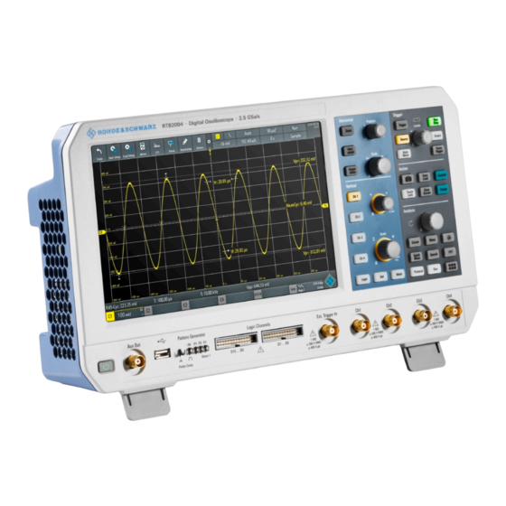
® Getting Started R&S RTB2000 Instrument Tour To shut down the instrument to standby state ► Press the STANDBY key. All current settings are saved, and the software shuts down. Now it is safe to power off the instrument. 2.1.3.3 Powering Off Powering off is required only if the instrument must be disconnected from all power supplies. - Page 30 ® Getting Started R&S RTB2000 Instrument Tour Figure 2-1: Front panel of R&S RTB2004 with 4 input channels 1 = Display 2 = Horizontal and vertical setup controls 3 = Trigger settings, action and analysis controls 4 = Analog input channels (2 channels at R&S RTB2002, 4 channels at R&S RTB2004) 5 = External trigger input 6 = Logic probe connectors (option R&S RTB-B1) 7 = Connectors for probe compensation and optional pattern generator (R&S RTB-B6)
- Page 31 ® Getting Started R&S RTB2000 Instrument Tour BNC inputs (4 and 5) The R&S RTB2000 has two or four channel inputs (4) to connect the input signals. The external trigger input (5) is used to control the measurement by an external signal. The trigger level can be set from -5 V to 5 V.
-
Page 32: Rear Panel
® Getting Started R&S RTB2000 Instrument Tour 2.2.1.2 Other Connectors on the Front Panel PATTERN GENERATOR (7) Connectors for the pattern generator P0, P1, P2, P3. The "Demo 1" signal is intended for demonstration purposes. PROBE COMP. (7) Probe compensation terminal to support adjustment of passive probes to the oscillo- scope channel. - Page 33 ® Getting Started R&S RTB2000 Instrument Tour Figure 2-2: Rear panel view of R&S RTB2000 1 = LAN connector 2 = USB connector, type B 3 = AC power supply connector and main power switch 4 = Kensington lock slot to secure the instrument against theft 5 = Loop for lock to secure the instrument against theft 6 = not used LAN (1)
-
Page 34: Operating Basics
® Operating Basics R&S RTB2000 Display Overview 3 Operating Basics 3.1 Display Overview The touchscreen display of the instrument shows the waveforms and measurement results, and also information and everything that you need to control the instrument. Figure 3-1: Display of the R&S RTB2000 with 4 channels 1 = toolbar 2 = trigger source, main trigger parameter (here: slope for edge trigger), trigger level 3 = trigger mode and sample rate... -
Page 35: Selecting The Application
® Operating Basics R&S RTB2000 Using the Touchscreen 3.2 Selecting the Application The "Apps Selection" dialog provides fast access to all available applications. ► There are several ways to open the "Apps Selection" dialog: ● Press the APPS SELECTION key. ●... - Page 36 ® Operating Basics R&S RTB2000 Using the Touchscreen Figure 3-2: Open the main menu and select a menu item Figure 3-3: Switch on or off (left) and select a parameter value (right) ► To close the menu: User Manual 1333.1611.02 ─ 04...
-
Page 37: Accessing Functionality Using Shortcuts
® Operating Basics R&S RTB2000 Using the Touchscreen Tap "Back", or tap into the diagram outside the menu. 3.3.2 Accessing Functionality Using Shortcuts The labels in information bar at the top of the display, the channel labels and also the results at the bottom provide shortcuts to the most important settings. -
Page 38: Using Gestures
® Operating Basics R&S RTB2000 Using the Touchscreen Figure 3-5: Enter numerical value and unit 3.3.4 Using Gestures Drag one finger Drag horizontally in the diagram to change the horizontal position of all waveforms. In frequency domain, the center frequency is changed. Drag vertically in the diagram to change the vertical position of the selected waveform. -
Page 39: Front Panel Keys
® Operating Basics R&S RTB2000 Front Panel Keys Spread or pinch two fingers in horizontal direction to change the horizontal scale of all waveforms. In frequency domain, the frequency span is changed. Swipe two fingers If the history option R&S RTB-K15 is installed, swipe two fingers in the diagram to scrolls through the history segments. -
Page 40: Analysis Controls
® Operating Basics R&S RTB2000 Front Panel Keys CLEAR SCREEN Deletes all waveforms, annotations and the measurement results of deleted wave- forms. All settings remain unchanged. Remote command: on page 359 DISPlay:CLEar[:SCReen] 3.4.2 Analysis Controls The controls in the ANALYSIS functional block open various menus for signal analysis. NAVIGATION The function of this universal rotary knob depends on the usage context: ●... -
Page 41: Using The Toolbar
® Operating Basics R&S RTB2000 Using the Toolbar Note: Channels other than the selected one are switched off in quick measurement mode. When you activate quick measurements, cursor measurements are automati- cally deactivated. Deactivate quick measurements before selecting the cursors. SEARCH Enables the search with the last configured setup. -
Page 42: Getting Help
® Operating Basics R&S RTB2000 Getting Help 4. Close the dialog box. 3.6 Getting Help In most menus and dialogs, graphics explain the meaning of the selected setting. For further information, you can open the help, which provides functional description of selected setting. - Page 43 ® Operating Basics R&S RTB2000 Getting Help To close the help window ► Tap "Help" on the top of the main menu, or tap the "Close" icon in the upper right corner of the help window. User Manual 1333.1611.02 ─ 04...
-
Page 44: Waveform Setup
® Waveform Setup R&S RTB2000 Connecting Probes and Displaying a Signal 4 Waveform Setup This chapter describes how to connect and set up probes, to adjust the horizontal and vertical settings, and to control the acquisition. 4.1 Connecting Probes and Displaying a Signal Risk of instrument damage Make sure to set the attenuation factor on the instrument according to the probe being used. -
Page 45: Vertical Setup
® Waveform Setup R&S RTB2000 Vertical Setup PRESET Resets the instrument to the default state, without analyzing the signal. The previous user-defined configuration is removed and all channels except for channel 1 are dis- abled. Remote command: *RST AUTOSET Analyzes the enabled analog channel signals, and adjusts the horizontal, vertical, and trigger settings to display stable waveforms. -
Page 46: Vertical Controls
® Waveform Setup R&S RTB2000 Vertical Setup 4.2.1 VERTICAL Controls CH <N> For each analog channel, a channel key is available. The key is illuminated in the channel color, if the channel is on. The effect of the keypress depends on state of the channel: ●... -
Page 47: Short Menu For Analog Channels
® Waveform Setup R&S RTB2000 Vertical Setup To get the maximum resolution of the waveform amplitude, make sure that the wave- forms cover most of the screen's height. Remote command: on page 253 CHANnel<m>:SCALe on page 278 CALCulate:QMATh:SCALe on page 281 REFCurve<m>:VERTical:SCALe LOGIC Enables the logic channels. -
Page 48: Vertical Settings
® Waveform Setup R&S RTB2000 Vertical Setup Functions in the short menu: ● "AC | DC": see "Coupling" on page 40 ● "Ground" on page 41 ● "Probe": opens the "Probe" menu, see ● "Off": turns off the channel. ● "Menu": opens the comprehensive "Vertical"... - Page 49 ® Waveform Setup R&S RTB2000 Vertical Setup "AC" AC coupling is useful if the DC component of a signal is of no inter- est. AC coupling blocks the DC component of the signal so that the waveform is centered on zero volts. "DC"...
- Page 50 ® Waveform Setup R&S RTB2000 Vertical Setup Vertical Scale Sets the vertical scale in Volts per division to change the displayed amplitude of the selected waveform. The current value is shown in the waveform label below the grid. Vertical scale directly affects the resolution of the waveform amplitude. To get the full resolution of the ADC, set up the waveforms to cover most of the height of the dia- gram.
-
Page 51: Probe Settings
® Waveform Setup R&S RTB2000 Vertical Setup "Fire" Display in fire colors. Yellow corresponds to rare occurrences of the samples, while red indicates frequent ones. "Default" Displays the waveform in its default monochrome color. 4.2.4 Probe Settings In the probe menu, you set the probe attenuation for the selected channel. You can select a default factor, for example "10:1", or enter a user-defined value. -
Page 52: Threshold Settings
® Waveform Setup R&S RTB2000 Vertical Setup 4.2.5 Threshold Settings A threshold is used for digitization of analog signals. If the signal value is higher than the threshold, the signal state is high (1 or true for the Boolean logic). Otherwise, the signal state is considered low (0 or false) if the signal value is below the threshold. -
Page 53: Label Settings
® Waveform Setup R&S RTB2000 Horizontal Setup 4.2.6 Label Settings In the "Label" menu, you can define a name label for the selected waveform. Access: CH <N> > "Label" (scroll down). Label Activates or deactivates the label display. The label is shown at the waveform on the right edge of the display. -
Page 54: Horizontal Controls
® Waveform Setup R&S RTB2000 Horizontal Setup Unlike vertical settings, which are waveform-specific, the horizontal settings apply to all active waveforms. There are several ways to adjust horizontal settings: ● Use the controls in the Horizontal functional block of the front panel to scale the waveforms, and to set the position. -
Page 55: Shortcuts For Horizontal Settings
® Waveform Setup R&S RTB2000 Horizontal Setup Turn clockwise to move the position to the right, and press the knob to reset the value to zero. The current value is shown in the information bar. In zoom and FFT, the knob sets the position in the active diagram. Tap the diagram that you want to adjust. -
Page 56: Horizontal Settings
® Waveform Setup R&S RTB2000 Horizontal Setup 1 = adjust horizontal scale 2 = adjust horizontal position 4.3.3 Horizontal Settings The comprehensive "Horizontal" menu contains all horizontal settings. In zoom mode, also zoom settings are listed in the menu. ► To open the menu, press the HORIZONTAL key. Reference Point Defines the time reference point in the diagram. -
Page 57: Acquisition Setup
® Waveform Setup R&S RTB2000 Acquisition Setup Horizontal Position Defines the trigger position, the time distance from the trigger point to the reference point (trigger offset). The trigger point is the zero point of the diagram. Changing the horizontal position, you can move the trigger, even outside the screen. If you want to see a section of the waveform some time before or after the trigger, enter this time as horizontal position. -
Page 58: Acquisition Settings
® Waveform Setup R&S RTB2000 Acquisition Setup 1 = start or stop a continuous acquisition, or start a single acquisition if SINGLE is active 2 = adjust the acquisition mode 3 = shows the current sample rate for information 4.4.2 Acquisition Settings Acquisition settings define the processing of the captured samples in the instrument. - Page 59 ® Waveform Setup R&S RTB2000 Acquisition Setup Acquire Mode Defines how the waveform is built from the captured samples. There are two general methods to build the waveform record: sample decimation and waveform arithmetic. Sample decimation reduces the data stream of the ADC to a stream of waveform points with lower sample rate and a less precise time resolution.
- Page 60 ® Waveform Setup R&S RTB2000 Acquisition Setup No. of Averages Defines the number of waveforms used to calculate the average waveform, if "Acquire Mode" = "Average". The higher the number, the better the noise is reduced. To restart the average calculation, press the CLEAR SCREEN key. Remote command: on page 263 ACQuire:AVERage:COUNt...
-
Page 61: Trigger
® Trigger R&S RTB2000 Trigger Controls 5 Trigger Triggering means to capture the interesting part of the relevant waveforms. Choosing the right trigger type and configuring all trigger settings correctly allows you to detect various incidents in signals. A trigger occurs if the trigger conditions are fulfilled. The instrument acquires continu- ously and keeps the sample points to fill the pretrigger part of the waveform record. - Page 62 ® Trigger R&S RTB2000 Trigger Controls TRIGGER Opens the "Trigger" menu. SOURCE Changes the analog trigger source. Press the key repeatedly until the required analog source is selected. If a digital source or serial bus was selected in the "Trigger" menu, or if the "Trigger Type"...
-
Page 63: Shortcuts For Trigger Settings
® Trigger R&S RTB2000 Shortcuts for Trigger Settings Remote command: on page 250 *TRG RUN STOP Starts and stops the continuous acquisition. A green light indicates a running acquisi- tion. A red light shows that acquisition is stopped. At slow timebases, a yellow light indicates that the acquisition is ongoing. -
Page 64: General Trigger Settings
® Trigger R&S RTB2000 General Trigger Settings 5.3 General Trigger Settings General trigger settings are independent of the trigger type. They are highlighted in the above figure and described in the current section. The other trigger settings are spe- cific for individual trigger types, and they are described in the following sections. Trigger Mode Toggles the trigger mode between "Auto"... - Page 65 ® Trigger R&S RTB2000 General Trigger Settings "Edge" Triggers on signal edges. Chapter 5.4, "Edge Trigger", on page 58. "Width" Triggers on pulse width. Chapter 5.5, "Width Trigger", on page 59. "Video" Triggers on various PAL, NTSC and HDTV standard video signals. Chapter 5.6, "Video Trigger", on page 62.
-
Page 66: Edge Trigger
® Trigger R&S RTB2000 Edge Trigger 5.4 Edge Trigger The edge trigger is the most common trigger type. The trigger occurs when the signal from the trigger source passes the trigger level in the specified direction (slope). Figure 5-1: Edge trigger event with positive slope (rising edge) ►... -
Page 67: Width Trigger
® Trigger R&S RTB2000 Width Trigger You can also drag the trigger level marker on the display, or turn the Levels knob. To set the trigger level to 50% of the signal amplitude, press the Levels knob. For width and timeout trigger, the trigger level is the threshold of the trigger source. Remote command: on page 268 TRIGger:A:LEVel<n>[:VALue]... - Page 68 ® Trigger R&S RTB2000 Width Trigger Figure 5-2: Pulse width is shorter (left) or longer (right) than a given duration (also known as glitch trigger) Figure 5-3: Pulse width is inside or outside an allowable time range 1 = Inside: min width < pulse < max width 2 = Outside: pulse <...
- Page 69 ® Trigger R&S RTB2000 Width Trigger Polarity.......................... 61 Comparison........................61 Time t..........................62 Variation........................62 Time t1, Time t2......................62 Threshold........................62 Hysteresis........................62 Polarity Sets the polarity of the pulse. You can trigger on: ● positive going pulse, the width is defined from the rising to the falling slopes. ●...
-
Page 70: Video Trigger
® Trigger R&S RTB2000 Video Trigger "Inside", "Out- Triggers on pulses inside or outside a range specified with "Time t1" side" and "Time t2". This method is an alternative setting to the range definition with "Time t" and "Variation". The values are interdependent. "Variation" and "Time t"... - Page 71 ® Trigger R&S RTB2000 Video Trigger First select the standard and the signal polarity, then decide to trigger on lines or fields and enter the specific settings. ► TRIGGER > "Trigger Type" = "Video" Figure 5-5: Video trigger menu Standard........................63 Signal..........................
-
Page 72: Pattern Trigger
® Trigger R&S RTB2000 Pattern Trigger Signal Selects the polarity of the signal. Note that the sync pulse has the opposite polarity. If the video modulation is positive, the sync pulses are negative. If the modulation is neg- ative, sync pulses are positive. The edges of the sync pulses are used for triggering, therefore incorrect polarity setting causes a sporadic triggering by the video informa- tion. - Page 73 ® Trigger R&S RTB2000 Pattern Trigger ► TRIGGER > "Trigger Type" = "Pattern" > "Edit Pattern" Figure 5-7: Pattern trigger with logic editor H | L | X, Set All......................65 And | Or.........................65 Duration.........................66 True | False........................66 Time limitation.......................
-
Page 74: Timeout Trigger
® Trigger R&S RTB2000 Timeout Trigger Duration The switch has the following two effects: ● Selects the mode of the True | False comparison. ● Enables or disables the Time limitation. True | False Defines whether the instrument triggers on fulfillment of the logical condition, or on vio- lation. - Page 75 ® Trigger R&S RTB2000 Timeout Trigger time Figure 5-8: Timeout trigger with range Stays High ► TRIGGER > "Trigger Type" = "Timeout" Figure 5-9: Timeout trigger menu Range Selects the relation of the signal level to the threshold: Stays High The signal level stays above the trigger level.
- Page 76 ® Trigger R&S RTB2000 Timeout Trigger Remote command: on page 268 TRIGger:A:LEVel<n>[:VALue] on page 256 CHANnel<m>:THReshold Hysteresis Hysteresis of the trigger source channel, see "Hysteresis" on page 44. Remote command: on page 257 CHANnel<m>:THReshold:HYSTeresis User Manual 1333.1611.02 ─ 04...
-
Page 77: Waveform Analysis
® Waveform Analysis R&S RTB2000 Zoom 6 Waveform Analysis ● Zoom........................69 ● Mathematics......................71 ● Reference Waveforms.................... 74 ● History and Segmented Memory (Option R&S RTB-K15)........78 ● Search........................84 6.1 Zoom The zoom magnifies a part of the waveform to view more details. The zoom is applied to all active analog and digital channels and math waveforms. - Page 78 ® Waveform Analysis R&S RTB2000 Zoom Figure 6-1: Zoom display: zoom is in the bottom window, normal waveform in the upper window = tap to activate zoom settings = tap to activate normal waveform settings 3 (blue) = zoom scale and width of the zoom area 4 (red) = zoom position = Sample rate in zoom window = horizontal scale and position of the normal waveform...
-
Page 79: Zoom Settings
® Waveform Analysis R&S RTB2000 Mathematics Now the knobs are applied to the normal waveform and adjust time scale and hori- zontal position of the waveform. 6.1.2 Zoom Settings Zoom settings are listed in the "Horizontal" menu. 1. If the zoom is off, press the ZOOM key to activate the zoom. 2. -
Page 80: Math Waveform Settings
® Waveform Analysis R&S RTB2000 Mathematics You can analyze math waveforms in the same way as channel waveforms: use zoom, perform automatic and cursor measurements, and save as reference waveform. To configure math waveforms 1. To enable the math waveform, press the MATH key. 2. - Page 81 ® Waveform Analysis R&S RTB2000 Mathematics Remote command: on page 277 CALCulate:QMATH:STATe Source 1, Source 2 Define the first and the second source for the mathematical operation (operands). The sources can be any active analog channel. Remote command: on page 277 CALCulate:QMATh:SOURce<m>...
-
Page 82: Reference Waveforms
® Waveform Analysis R&S RTB2000 Reference Waveforms 6.3 Reference Waveforms To compare waveforms and analyze differences between them, you can display refer- ence waveforms. Reference waveforms are waveform data stored in the internal reference storages. Four reference waveforms are available and can be displayed: R1 to R4. The display of a reference waveform is independent from the display of the source waveform;... - Page 83 ® Waveform Analysis R&S RTB2000 Reference Waveforms 2. To create a reference waveform from an active waveform: a) Select the "Source" waveform. b) Select the target "Reference". c) Tap "Copy" The new reference waveform is created on top of its origin, and it has the focus. 3.
-
Page 84: Settings For Reference Waveforms
® Waveform Analysis R&S RTB2000 Reference Waveforms 6.3.2 Settings for Reference Waveforms ► To open the "References" menu: a) Tap the menu icon in the lower right corner of the screen. b) Scroll down. Select "References". Source...........................76 Reference........................76 Copy..........................77 State..........................77 Load Reference......................77 Load... - Page 85 ® Waveform Analysis R&S RTB2000 Reference Waveforms Copy Copies the "Source" waveform to the selected reference waveform. The reference waveform is kept until you update it or load another waveform to the reference. Remote command: on page 280 REFCurve<m>:UPDate State Activates the reference waveform and displays it.
-
Page 86: History And Segmented Memory (Option R&S Rtb-K15)
® Waveform Analysis R&S RTB2000 History and Segmented Memory (Option R&S RTB-K15) 6.4 History and Segmented Memory (Option R&S RTB- K15) The option R&S RTB-K15, history and segmented memory, accesses the data of previ- ously acquired waveforms and provides them for further analysis. Using this option, you can analyze, for example, signals that occur in short bursts with long idle times, packet communication on serial buses, radar pulses, and laser pulses. -
Page 87: Segment Table
® Waveform Analysis R&S RTB2000 History and Segmented Memory (Option R&S RTB-K15) ● All logic channels if at least one logic is active (with option R&S RTB-B1). ● Decoded bus data if the bus is active (with at least one serial protocol option R&S RTB-K1, -K2, or -K3). -
Page 88: Displaying History Segments
® Waveform Analysis R&S RTB2000 History and Segmented Memory (Option R&S RTB-K15) Next Steps forward to the next newer segment. Repeat If selected, the playback of the selected history segments repeats automatically. Remote command: ...:HISTory:REPLay Speed Sets the speed of the history playback: automatic, slow, middle, or fast. Remote command: ...:HISTory:SPEed Save... -
Page 89: Exporting History Data
® Waveform Analysis R&S RTB2000 History and Segmented Memory (Option R&S RTB-K15) 1. Activate the history. 2. Set the "Time Format" to be shown in the table: absolute or relative time. 3. Set the "Speed". 4. To play back all segments once, tap "Run". 5. - Page 90 ® Waveform Analysis R&S RTB2000 History and Segmented Memory (Option R&S RTB-K15) 7. To select the target folder, tap the "Destination" field. The location is always "/USB_FRONT", saving to internal storage is not provided. 8. Tap "Save". A message shows the progress of the saving process. 9.
- Page 91 ® Waveform Analysis R&S RTB2000 History and Segmented Memory (Option R&S RTB-K15) Figure 6-3: Content of a segment table file Waveforms Each history segment is saved to a separate file, and all segment files are written to a folder that contains only the files of the saved acquisition. You can specify the name of the folder.
-
Page 92: Search
® Waveform Analysis R&S RTB2000 Search In addition to the data files, an index file is written. The index file delivers information on the files and the segments. For each segment, the segment index, save date and time, and the filename is listed. Figure 6-6: Content of a history index file 6.5 Search 6.5.1 Search Conditions and Results... - Page 93 ® Waveform Analysis R&S RTB2000 Search Figure 6-7: Search results and settings during running acquisition Remote commands to get search results: ● on page 295 SEARch:RCOunt? ● on page 294 SEARch:RESult:ALL? ● on page 295 SEARch:RESult<n>? ● on page 294 SEARch:RESDiagram:SHOW ●...
- Page 94 ® Waveform Analysis R&S RTB2000 Search 3. In the "Search" menu, select "Track event". The selected event is moved to the reference point. If you select another event, it is shown at the same position. To save search results 1. In the upper right corner of the search result table, tap the "Save" symbol. 2.
-
Page 95: General Search Settings
® Waveform Analysis R&S RTB2000 Search 5. Tap "Save". The data is saved to a CSV file. 6.5.2 General Search Settings General search settings are independent of the search type. They are described in the current section. The specific settings for individual search types are described in the following sections. - Page 96 ® Waveform Analysis R&S RTB2000 Search "Rise/Fall time" The rise or fall time search finds slopes with an exact rise or fall time, or rise/fall times shorter or longer than a given limit, or rise/fall times inside or outside a given time range. For settings, see Chapter 6.5.6, "Rise/Fall Time Search",...
-
Page 97: Edge Search
® Waveform Analysis R&S RTB2000 Search 6.5.3 Edge Search Similar to the edge trigger, an edge search result is found when the waveform passes the given level in the specified direction. ► SEARCH > "Search Type" = "Edge" > "Setup" Slope Sets the slope to be found: rising, falling, or both slopes. -
Page 98: Width Search
® Waveform Analysis R&S RTB2000 Search 6.5.4 Width Search The width search finds pulses with an exact pulse width, or pulses shorter or longer than a given time, or pulses inside or outside the allowable time range. It is similar to the width trigger. -
Page 99: Peak Search
® Waveform Analysis R&S RTB2000 Search The comparison works like the comparison of the width trigger, see Chapter 5.5, "Width Trigger", on page 59. Remote command: on page 285 SEARch:TRIGger:WIDTh:RANGe Width Sets the reference pulse width, the nominal value for comparisons. Remote command: on page 286 SEARch:TRIGger:WIDTh:WIDTh... - Page 100 ® Waveform Analysis R&S RTB2000 Search ► SEARCH > "Search Type" = "Rise/Fall Time" > "Setup" Edge Sets the slope to be found: ● "Rising" to search for rise time ● "Falling" to search for fall time ● "Both" to search for rise and fall time Remote command: on page 287 SEARch:TRIGger:RISetime:SLOPe...
-
Page 101: Runt Setup
® Waveform Analysis R&S RTB2000 Search Remote command: on page 287 SEARch:TRIGger:RISetime:RANGe Rise/Fall Time Sets the reference rise or fall time, the nominal value for comparisons. Remote command: on page 288 SEARch:TRIGger:RISetime:TIME Variation Sets a range Δt to the reference "Rise/Fall Time" if comparison is set to "Equal" or "Not equal". -
Page 102: Data2Clock
® Waveform Analysis R&S RTB2000 Search Upper Level Sets the upper voltage threshold for runt detection. A negative runt crosses the upper level twice without crossing the lower level. Remote command: on page 289 SEARch:TRIGger:LEVel:RUNT:UPPer Lower Level Sets the lower voltage threshold for runt detection. A positive runt crosses the lower level twice without crossing the upper level. - Page 103 ® Waveform Analysis R&S RTB2000 Search Clock Selects the input channel of the clock signal. Remote command: on page 290 SEARch:TRIGger:DATatoclock:CSOurce Data Selects the input channel of the data signal. Remote command: on page 284 SEARch:SOURce Level Set the voltage levels for clock and data signals. The crossing of clock level and clock edge defines the start point for setup and hold time.
-
Page 104: Pattern Search
® Waveform Analysis R&S RTB2000 Search "Rising" Only positive clock edges are considered. "Falling" Only negative clock edges are considered. "Either" The clock edges next to the data edge are considered regardless of the clock slope. Use this setting, for example, for signals with double data rate. - Page 105 ® Waveform Analysis R&S RTB2000 Search Threshold, Hysteresis Sets the search threshold value for each analog channel. If the signal value is higher than the threshold, the signal state is high. Otherwise, the signal state is considered low. For each analog channel, set a hysteresis to avoid unwanted search results caused by noise oscillation of the signal.
- Page 106 ® Waveform Analysis R&S RTB2000 Search "NOR" "Not or" operator, no channel has the required state. Remote command: on page 292 SEARch:TRIGger:PATTern:FUNCtion Comparison Sets the condition how the duration of a steady pattern is compared with the given limit. The three settings "Width" "Variation" and "Comparison" define the time range how long the true result of the state pattern must be valid.
-
Page 107: Measurements
® Measurements R&S RTB2000 Quick Measurements 7 Measurements 7.1 Quick Measurements Quick measurement performs a set of automatic measurements on the selected input channel. The measurements cannot be configured. The results are displayed directly at the waveform (WF) or in the bottom result line (L) and are updated continuously. If the instrument detects a period in the signal, the quick measurement measures the first cycle and displays the results. -
Page 108: Automatic Measurements
® Measurements R&S RTB2000 Automatic Measurements Quick measurement is not available on math and reference waveforms. Channels other than the selected one are switched off in quick measurement mode. When quick measurement is active, cursor measurements are not possible, but you can use auto- matic measurements in parallel. -
Page 109: Measurement Types
® Measurements R&S RTB2000 Automatic Measurements Figure 7-1: Results of four active measurements If a result cannot be determined, "?" is displayed. Adjust the horizontal and vertical set- tings if the instrument cannot measure. If the measurement result is outside the measurement range and clipping occurs, the results are marked with "clipping+"... - Page 110 ® Measurements R&S RTB2000 Automatic Measurements 7.2.2.1 Horizontal Measurements (Time) Meas. type Symbol Description Graphic / formula Frequency Frequency of the signal, reciprocal value of the measured f = 1 / T first period. in Hz Period Time of the first period, measured on the 50% level. The measurement requires at least one complete period of the in s signal.
- Page 111 ® Measurements R&S RTB2000 Automatic Measurements Meas. type Symbol Description Graphic / formula Delay Time difference between two slopes of the same or different waveforms, measured on the 50% level. in s Not available for cursor measurements Phase = Δt / T * 360° Phase Phase difference between two waveforms, measured on the 50% level.
- Page 112 ® Measurements R&S RTB2000 Automatic Measurements Meas. type Symbol Description Graphic / formula Peak+ Maximum value within the displayed waveform. Peak- Minimum value within the displayed waveform. Overshoot +Ovr Overshoot of a square wave after a rising or falling edge. It ...
-
Page 113: Settings For Automatic Measurements
® Measurements R&S RTB2000 Automatic Measurements 7.2.2.3 Counting Meas. type Symbol Description Graphic / formula Positive pulse CntP+ Number of positive pulses on the display. The mean value of the signal is determined. If the signal passes the mean value, an edge is counted. A positive pulse is counted if a rising edge and a following falling edge are detected. - Page 114 ® Measurements R&S RTB2000 Automatic Measurements Meas. Place Selects one of the four available measurement places to be configured or activated. Measure <n> Activates or deactivates the selected measurement. Remote command: on page 307 MEASurement<m>[:ENABle] Type Defines the measurement type to be performed on the selected source. Depending on the type, different results are displayed in the result line.
-
Page 115: Cursor Measurements
® Measurements R&S RTB2000 Cursor Measurements Remote command: on page 311 MEASurement<m>:STATistics:RESet Delete all Measurements Deactivates all active measurements. Reference Level Set the lower and upper reference levels for rise and fall time measurements. Sets also the middle reference level used for phase and delay measurements. The levels are defined as percentages of the high signal level. - Page 116 ® Measurements R&S RTB2000 Cursor Measurements Figure 7-3: Cursor measurement with vertical and horizontal cursors and Set To Trace Results = below the grid Cursor lines 1, 2, 3 = not active Cursor line 4 = active, can be moved by turning the NAVIGATION knob To configure cursor measurements 1.
-
Page 117: Cursor Settings
® Measurements R&S RTB2000 Cursor Measurements 7.3.1 Cursor Settings ► To open the "Cursor" menu: a) Tap the "Menu" icon in the lower right corner of the screen. b) Scroll down. Select "Cursor". Cursor Activates or deactivates the cursor measurement. Remote command: on page 317 CURSor<m>:STATe... - Page 118 ® Measurements R&S RTB2000 Cursor Measurements "Vertical & Combines the "Horizontal" cursor and "Vertical" cursor measure- Horiz." ments. Two horizontal and two vertical cursor lines are set. The vol- tages and times are measured at the cursor positions, as well as the delta of the voltage and time values.
- Page 119 ® Measurements R&S RTB2000 Cursor Measurements Set To Screen Resets the cursors to their initial positions. Reset is helpful if the cursors have disap- peared from the display or need to be moved for a larger distance. Remote command: on page 320 CURSor<m>:SSCReen User Manual 1333.1611.02 ─...
-
Page 120: Applications
® Applications R&S RTB2000 Mask Testing 8 Applications 8.1 Mask Testing Masks are used to determine whether the amplitude of a signal remains within speci- fied limits, e.g. to detect errors or test compliance of digital signals. 8.1.1 About Masks and Mask Testing Masks A mask is specified by an upper and a lower limit line. -
Page 121: Using Masks
® Applications R&S RTB2000 Mask Testing File format for masks: MSK MSK is the specific binary format for masks of the R&S RTB2000. It contains pairs of amplitude values (in divisions) , their sample indexes and current instrument settings. Thus, the amplitude values are not related to time and voltage. The mask data is saved in the internal storage and can be loaded back when needed. - Page 122 ® Applications R&S RTB2000 Mask Testing ● For detailed setup: – Tap "Setup" to open the "Mask" menu. – Change "Width Y", "Width X" and/or "Stretch Y". 5. To save the mask for later use, tap "Save". To load a mask 1.
-
Page 123: Mask Window
® Applications R&S RTB2000 Mask Testing 6. Tap "Reset" to delete the results. 7. To finish the test, tap "Stop". 8.1.3 Mask Window The mask window provides the most important function to set up a mask, and to run the test. Reset Deletes all test results. -
Page 124: Mask Menu
® Applications R&S RTB2000 Mask Testing Size+, Size- Enlarges or decreases the mask in x- and y-direction. Save, Load Saves the created mask to file, or loads a previously saved mask. The file format is MSK. Remote command: on page 324 MASK:SAVE on page 324 MASK:LOAD... - Page 125 ® Applications R&S RTB2000 Mask Testing Test Performs a mask test for the selected signal, i.e. the signal amplitudes are compared with the specified mask. If the amplitude exceeds the limits of the mask, a violation is detected. Remote command: on page 326 MASK:TEST Copy Channel...
-
Page 126: Fft Analysis
® Applications R&S RTB2000 FFT Analysis Load Mask Opens a file explorer to select a previously stored mask. The selected mask is loaded and can be used for a subsequent test. Remote command: on page 324 MASK:LOAD Actions Opens a submenu to select the actions to be taken when a violation against the mask limits occurs. -
Page 127: Fft Display
® Applications R&S RTB2000 FFT Analysis 8.2.1 FFT Display When you activate FFT display, two windows are displayed: the signal vs. time at the top, the result of the FFT analysis at the bottom. In addition, FFT-specific parameters can be set in the FFT shortcuts. 1 = Enable FFT 2 = Signal vs. -
Page 128: Performing Fft Analysis
® Applications R&S RTB2000 FFT Analysis 9 = Resolution bandwidth 10 = Channel providing input data 11 = Opens the FFT short menu 12 = Amplitude vertical scale (range per division) Data source FFT analysis is performed on the data captured from one of the active input channels, or on ona of the active math or reference waveforms. - Page 129 ® Applications R&S RTB2000 FFT Analysis Shortcuts for FFT 1 = Start frequency 2 = Stop frequency 3 = Center 4 = Span 5 = Resolution bandwidth (RBW) Source Selects the channel for which the captured data is analyzed for the FFT. You can select one of the active input channels, math or reference waveforms.
- Page 130 ® Applications R&S RTB2000 FFT Analysis "Hamming" The Hamming window is bell shaped. Its value is not zero at the bor- ders of the measuring interval. Thus, the noise level inside the spec- trum is higher than Hanning or Blackman, but smaller than the rectan- gular window.
- Page 131 ® Applications R&S RTB2000 FFT Analysis "Spectrum" The currently measured value for each frequency is displayed. "Min Hold" The minimum value for each frequency over all measurements is dis- played. Using the min hold trace mode is a good way to highlight signals within noise or suppress intermittent signals.
-
Page 132: Xy-Diagram
® Applications R&S RTB2000 XY-Diagram Remote command: on page 331 SPECtrum:FREQuency:STARt Stop Defines the stop frequency of the displayed frequency span. Remote command: on page 331 SPECtrum:FREQuency:STOP Center Defines the frequency in the center of the displayed span. To set the center frequency, you can also use the Position keys. Remote command: on page 330 SPECtrum:FREQuency:CENTer... - Page 133 ® Applications R&S RTB2000 XY-Diagram Remote command: on page 334 DISPlay:MODE To analyze the signal in the XY-diagram, you can use cursor measurements. You can select specific cursor measurement types:"Voltage X", "Voltage Y1", "Voltage Y2" use 2 cursor lines, "Voltage X-Y1" and "Voltage X-Y2" use 4 cursor lines. Source X Defines the source to be displayed in x-direction in an XY-diagram, replacing the usual timebase.
-
Page 134: Digital Voltmeter
® Applications R&S RTB2000 Digital Voltmeter Remote command: on page 335 DISPlay:XY:Y2Source 8.4 Digital Voltmeter The integrated three-digit digital voltmeter simplifies measurements, in particular for service personnel. You can measure up to four parameters on different sources at the same time and define the position of the measurement results. The following DVM measurements are available: ●... -
Page 135: Meter Settings
® Applications R&S RTB2000 Digital Voltmeter To deactivate meter measurements ► Use one of the following ways: ● Tap the "Meter" icon on the toolbar again. ● Close the "Meter" result box. 8.4.2 Meter Settings ► To open the "Meter" configuration menu, tap inside the "Meter" result box. Meter (on/off) Activates or deactivates the digital voltmeter with the last configuration. -
Page 136: Trigger Counter
® Applications R&S RTB2000 Trigger Counter Meter Selects one of the four available meter measurements. The configuration of the selected meter is displayed in the menu. Source Selects an analog channel as the source of the selected meter measurement. Remote command: on page 336 DVM<m>:SOURce Type... - Page 137 ® Applications R&S RTB2000 Trigger Counter Remote commands: ● on page 338 TCOunter:ENABle ● on page 338 TCOunter:RESult[:ACTual]:FREQuency? ● on page 338 TCOunter:RESult[:ACTual]:PERiod? User Manual 1333.1611.02 ─ 04...
-
Page 138: Documenting Results
® Documenting Results R&S RTB2000 9 Documenting Results The R&S RTB2000 can store various data to files for further usage, analysis and reporting: ● Instrument settings: Chapter 9.1, "Saving and Loading Instrument Settings", on page 131 ● Waveforms: Chapter 9.2, "Exporting Waveforms", on page 132 ●... -
Page 139: Saving And Loading Instrument Settings
® Documenting Results R&S RTB2000 Saving and Loading Instrument Settings The supported file system in all storage locations is FAT. 9.1 Saving and Loading Instrument Settings To repeat measurements or tests at different times or perform similar measurements with different test data, you can save the used configuration settings. Furthermore, it can be helpful to refer to the configuration settings of a particular measurement when analyzing the results. -
Page 140: Exporting Waveforms
® Documenting Results R&S RTB2000 Exporting Waveforms Tap "Save" to start writing the data. Remote command: on page 358 MMEMory:STORe:STATe Load Opens a file explorer to select an instrument setup file to be loaded to the instrument. To change the storage location, select "Destination" > "Location". Tap "Load"... -
Page 141: Waveform Export Settings
® Documenting Results R&S RTB2000 Exporting Waveforms 9.2.1 Waveform Export Settings Destination The destination /USB_FRONT is only active, if a USB flash drive is connected to the front USB port. Tap the field and select the target folder. Tap "Accept Dir." to confirm selection. Remote command: on page 350 EXPort:WAVeform:NAME... -
Page 142: Waveform File Formats
® Documenting Results R&S RTB2000 Exporting Waveforms Remote command: on page 349 EXPort:WAVeform:SOURce Points Selects the number of data points to be saved in the waveform file. ● "Display Data": Saves all currently displayed waveform samples. ● "Acq. Memory": Saves all data samples that are stored in the acquisition memory. This setting takes effect only for stopped acquisitions. - Page 143 ® Documenting Results R&S RTB2000 Exporting Waveforms Example CSV1: Waveform of channel 1, single values in s,CH1 in V -1.1996E-02,1.000E-02 -1.1992E-02,1.000E-02 -1.1988E-02,1.000E-02 -1.1984E-02,1.000E-02 Example CSV2: Waveform of channel 1, pairs of values in s,CH1 in V -2.9980E+00,2.000E-05 -2.9980E+00,1.400E-04 -2.9960E+00,-1.800E-04 -2.9960E+00,1.400E-04 -2.9940E+00,-1.800E-04 -2.9940E+00,1.400E-04 Example CSV3: FFT...
-
Page 144: Annotations
® Documenting Results R&S RTB2000 Annotations You can set the word order: BIN MSBF saves data in Big Endian order - beginning with the MSB (Most Significant Byte) and ending with the LSB (Least Significant Byte). BIN LSBF saves data beginning with the LSB and ending with the MSB. Pairs of values are listed as two subsequent single values, without any identification. -
Page 145: Screenshots
® Documenting Results R&S RTB2000 Screenshots 1 = Annotations on / off 2 = Drawing tools 3 = Text tool 4 = Eraser to delete single lines 5 = Remover to delete all annotations 3. To finish, tap the "Annotation" icon in the toolbar again. 9.4 Screenshots You can create and save screenshots of the current display of your waveforms and measurement results. - Page 146 ® Documenting Results R&S RTB2000 Screenshots To configure screenshots: 1. Press the SAVE LOAD key. 2. Select "Screenshots". 3. Adjust the target directory ("Destination"), filename, format, and color mode. You can save the current display with "Save", or close the dialog box. The screen- shot settings are saved and applied when you create screenshots with the key.
-
Page 147: Quick Save With Onetouch
® Documenting Results R&S RTB2000 Quick Save with OneTouch ● "Inverted": Inverts the colors of the output, so that a dark waveform is printed on a white background. ● "Inverted (gray)": Inverts the colors of the output, and converts to a monochrome image. -
Page 148: Export And Import
® Documenting Results R&S RTB2000 Export and Import 6. To save the data now, tap "Save". 7. Close the dialog. 8. Press the key each time when you want to save the data. 9.6 Export and Import To copy reference waveforms and instrument settings from the internal storage to USB flash drive or vice versa, the "Import Export"... - Page 149 ® Documenting Results R&S RTB2000 Export and Import Import/export menu for instrument settings Import/export menu for reference waveforms 4. Define the source file for the copy operation: a) Tap "Source File". b) If necessary, change the storage location with "Location". c) Select the folder that contains the source file.
-
Page 150: General Instrument Setup
® General Instrument Setup R&S RTB2000 Instrument Settings 10 General Instrument Setup The general instrument settings are available in all operating modes. 10.1 Instrument Settings ► To open the "Setup" menu: a) Tap the "Menu" rhomb icon in the lower right corner of the screen. b) Scroll down. - Page 151 ® General Instrument Setup R&S RTB2000 Instrument Settings Interface Activates or deactivates additional instrument interfaces. Use these interfaces to com- municate with the instrument, for example to read out data or automate the measuring station. USB and Ethernet (LAN) interfaces are installed in the rear panel. After select- ing an interface, tap "Parameter"...
- Page 152 ® General Instrument Setup R&S RTB2000 Instrument Settings "10 MHz" Outputs a 10 MHz reference frequency. "Function Generator" Outputs the waveform specified in the "Function Generator" dialog. "Mask Violation" Outputs a pulse when a mask is violated. This setting is only available if a mask is specified in the "Mask" dia- log.
-
Page 153: Display Settings
® General Instrument Setup R&S RTB2000 Display Settings "Clear Password" Deletes the password and allows all users enabling or disabling the education mode. You have to enter the password first before you can delete it. Using the remote command, you can clear the education mode pass- word without using the password. - Page 154 ® General Instrument Setup R&S RTB2000 Display Settings ► To remove all waveforms and results from the display, press the CLEAR SCREEN key at the front panel. Persistence Defines the persistence (afterglow effect) of the waveform on the display. "Off" Deactivates persistence.
- Page 155 ® General Instrument Setup R&S RTB2000 Display Settings Remote command: on page 362 DISPlay:INTensity:GRID LED Brightness ← Intensities Defines the intensity of illuminated front panel keys and rotary knobs in percent. Remote command: on page 361 DISPlay:INTensity:BACKlight Dots Only If activated, only the individual data points are displayed. If deactivated, the individual data points are connected by a line.
-
Page 156: Resetting The Instrument
® General Instrument Setup R&S RTB2000 Performing a Self-Alignment Track Grid ← Grid If enabled, the grid moves with the waveforms, if you change the waveform's position in horizontal or vertical direction. If disabled (= default), the grid remains centered on the display, if you change the waveform's position. -
Page 157: Setting The Data, Time And Language
® General Instrument Setup R&S RTB2000 Setting the Data, Time and Language Preparing the instrument for self-alignment Make sure that the instrument has been running and warming up before you start the self-alignment. The minimum warm-up time is indicated in the data sheet. Before the self-alignment, remove all probes, leads, and other connected lines from the instrument input. -
Page 158: Adjusting Passive Probes
® General Instrument Setup R&S RTB2000 Adjusting Passive Probes 2. Scroll down the menu. Tap "Date & Time". 3. Select the date: Scroll the year, month, and day columns until the required date is displayed. 4. Select the time: Scroll the hour and minute columns until the required time is dis- played. -
Page 159: Options
® General Instrument Setup R&S RTB2000 Options ance of the probe-oscilloscope system and introduces measurement errors resulting in distorted waveforms and inaccurate results. Two connector pins for compensation are located at the front panel. The left pin is on ground level. The next pin supplies a square wave signal for the adjustment. 1. -
Page 160: Activating Options
® General Instrument Setup R&S RTB2000 Updating the Firmware 10.8.1 Activating Options Consult your sales representative and provide the material number, serial number, and the device ID of your instrument to get a license key. You find this information in "Setup"... - Page 161 ® General Instrument Setup R&S RTB2000 Updating the Firmware 2. Connect the USB flash drive to the USB connector at the front of the instrument. 3. Tap the "Menu" icon in the lower right corner of the screen. 4. Scroll down the menu. Tap "Setup". 5.
-
Page 162: Network Connections And Remote Operation
® Network Connections and Remote Operation R&S RTB2000 LAN Connection 11 Network Connections and Remote Opera- tion 11.1 LAN Connection The R&S RTB2000 is equipped with a network interface and can be connected to an Ethernet LAN (local area network). A LAN connection is necessary for remote control of the instrument, and for access from a computer using a web browser. - Page 163 ® Network Connections and Remote Operation R&S RTB2000 LAN Connection Figure 11-1: Example of the Ethernet setup dialog with various address settings Description of settings IP Mode Selects the Internet protocol mode: ● "Manual": To be used if the network does not support dynamic host configuration protocol (DHCP).
-
Page 164: Usb Connection
® Network Connections and Remote Operation R&S RTB2000 USB Connection IP Port, VXI-11 Port Specify the IP port number (default = 5025) and the VXI-11 port number (default = 1024). Remote command: on page 368 SYSTem:COMMunicate:INTerface:ETHernet:IPPort on page 368 SYSTem:COMMunicate:INTerface:ETHernet:HTTPport Link "Yes", if the instrument is connected to a local area network via the LAN interface on the rear panel. - Page 165 ® Network Connections and Remote Operation R&S RTB2000 USB Connection 2. Open the "Setup" menu. 3. Tap "Interface". 4. Tap "USB" to select USB connection. 5. Tap "Parameter". 6. Select the USB mode. ● USB TMC (Test & Measurement Class) ●...
-
Page 166: Remote Access Using A Web Browser
® Network Connections and Remote Operation R&S RTB2000 Remote Access Using a Web Browser 11.3 Remote Access Using a Web Browser The R&S RTB2000 firmware contains a web server. If a LAN connection is estab- lished, you can access the instrument remotely using a web browser on the control computer. -
Page 167: Screenshot
® Network Connections and Remote Operation R&S RTB2000 Remote Access Using a Web Browser 11.3.3 Screenshot The "Screenshot" page shows a copy of the instrument's display. It also provides instrument control functions and screenshot settings. Instrument control ● "Run" and "Stop" = start and stop continuous acquisition, same as RUN STOP key on the instrument. -
Page 168: Scpi Device Control
® Network Connections and Remote Operation R&S RTB2000 Remote Access Using a Web Browser Screenshots ● "Auto refresh" and "Update" Get the current screen content from the instrument. With "Auto refresh", you can set the interval of automatic updates. ● "Format"... -
Page 169: Save/Recall
® Network Connections and Remote Operation R&S RTB2000 Remote Access Using a Web Browser 11.3.5 Save/Recall On the "Save/Recall" page, you can save waveform data and instrument settings to a file - either on the computer (local file) or on the instrument (remote device). On the computer, the default storage directory is the download folder, but you can change the directory using the download functions of your browser. -
Page 170: Network Settings
® Network Connections and Remote Operation R&S RTB2000 Remote Access Using a Web Browser 11.3.6 Network Settings On the "Network Setting" page, you can change the port settings, switch off DHCP address and enter an IP address in a more comfortable way than directly on the instru- ment. -
Page 171: Change Password
® Network Connections and Remote Operation R&S RTB2000 Remote Access Using a Web Browser 11.3.7 Change Password On the "Change Password" page, you can change or remove the password to protect remote access to the instrument. Alternatively, you can change the password in the Ethernet settings dialog on the instrument. -
Page 172: Serial Bus Analysis
® Serial Bus Analysis R&S RTB2000 Basics of Protocol Analysis 12 Serial Bus Analysis Using the R&S RTB2000 and additional options, you can analyze the following serial protocols: ● SPI (Serial Peripheral Interface with 3 lines) and SSPI (Serial Peripheral Interface with 2 lines) - requires option R&S RTB-K1 Chapter 12.2, "SPI/SSPI Bus (Option R&S RTB-K1)",... -
Page 173: Protocol - Common Settings
® Serial Bus Analysis R&S RTB2000 Basics of Protocol Analysis ● Protocol - Common Settings................. 165 ● Display Settings....................167 ● Bus Table: Decode Results...................167 ● Labels......................168 ● Label List.......................169 12.1.1 Protocol - Common Settings ► To open the protocol setup, press the PROTOCOL key. The common settings in the "Protocol"... - Page 174 ® Serial Bus Analysis R&S RTB2000 Basics of Protocol Analysis ● SPI (2 wires) ● SSPI (3 wires) ● ● UART ● ● Remote command: on page 370 BUS<b>:TYPE Decode Enables protocol decoding for the selected bus. Remote command: on page 370 BUS<b>:STATe Configuration Opens or closes the dialog box with configuration settings of the selected bus.
-
Page 175: Display Settings
® Serial Bus Analysis R&S RTB2000 Basics of Protocol Analysis Bus Table Opens a menu to define bus table settings for the decoded frames of the acquisition. Chapter 12.1.3, "Bus Table: Decode Results", on page 167. Label Opens a menu to define a label for the selected bus. Chapter 12.1.4, "Bus Labels", on page 168. -
Page 176: Bus Labels
® Serial Bus Analysis R&S RTB2000 Basics of Protocol Analysis 2. Stop the acquisition. 3. In the "Bus Table" menu, select "Track Frame". 4. Tap a frame in the bus table. The start of the selected frame is marked by a line and a rhomb. This marker is moved to the center of the diagram, followed by the decoded data. -
Page 177: Label List
® Serial Bus Analysis R&S RTB2000 Basics of Protocol Analysis Label Displays or hides the bus label. The bus label is shown on the right side of the display at the bus signal, and in the bus table. The bus and its label are only visible, if "Decode"... - Page 178 ® Serial Bus Analysis R&S RTB2000 Basics of Protocol Analysis You can also also use the label list to trigger on an identifier or address. Instead of entering the value, you select the name, which is defined in the label list. The format of label list files is PTT.
- Page 179 ® Serial Bus Analysis R&S RTB2000 Basics of Protocol Analysis a) "<Protocol> Trigger" = "Identifier", or "Identifier + Data", or "Address", or "Address and Data". b) Tap "Symbolic ID". c) Select the label. The list provides all symbolic names that are defined in the loaded file.
-
Page 180: Spi/Sspi Bus (Option R&S Rtb-K1)
® Serial Bus Analysis R&S RTB2000 SPI/SSPI Bus (Option R&S RTB-K1) The format of the numeric value is indicated by a suffix. The following formats are sup- ported: Format Suffix Example Decimal <empty> 106, DeviceName 106d, DeviceName Hexadecimal 6Ah, DeviceName or prefix: 0x6A, DeviceName Octal 152o, DeviceName... -
Page 181: Spi/Sspi Configuration
® Serial Bus Analysis R&S RTB2000 SPI/SSPI Bus (Option R&S RTB-K1) Main characteristics of SPI are: ● Master-slave communication ● No device addressing; The slave is accessed by a chip select, or slave select line. ● No acknowledgement mechanism to confirm receipt of data ●... - Page 182 ® Serial Bus Analysis R&S RTB2000 SPI/SSPI Bus (Option R&S RTB-K1) 5. Select the sources of the signal lines, the channels to which the lines are connec- ted. 6. Set the threshold. Use one of the following methods: ● Tap "Find Threshold". The instrument evaluates the signal and sets the thresh- old.
- Page 183 ® Serial Bus Analysis R&S RTB2000 SPI/SSPI Bus (Option R&S RTB-K1) Threshold, Find Threshold..................175 Word Size........................176 Idle Time........................176 Chip Select Selects the input channel of the chip select (CS) line. Only available in the SPI setup. If the MSO option R&S RTB-B1 is installed, you can use logic channels as source. Remote command: on page 373 BUS<b>:SPI:CS:SOURce...
-
Page 184: Spi/Sspi Trigger
® Serial Bus Analysis R&S RTB2000 SPI/SSPI Bus (Option R&S RTB-K1) Remote command: on page 256 CHANnel<m>:THReshold on page 256 CHANnel<m>:THReshold:FINDlevel on page 432 DIGital<m>:THReshold Word Size Sets the word length (or symbol size), which is the number of bits in a message. The maximum word length is 32 bit. - Page 185 ® Serial Bus Analysis R&S RTB2000 SPI/SSPI Bus (Option R&S RTB-K1) ● "Serial Pattern": a bit pattern in the message 5. If "Serial Pattern" is selected, the SPI trigger setup dialog expands to define the serial pattern. SPI/SSPI trigger settings The trigger settings are shown below the bus configuration settings.
-
Page 186: Spi/Sspi Decode Results
® Serial Bus Analysis R&S RTB2000 SPI/SSPI Bus (Option R&S RTB-K1) Remote command: on page 378 TRIGger:A:SPI:MODE Bit Offset Specifies the number of bits before the first bit of the pattern. These bits are ignored. The first bit after frame start is Bit 1. For example, with bit offset = 2, Bit 1 and Bit 2 are ignored, and the pattern starts with Bit 3. -
Page 187: I²C (Option R&S Rtb-K1)
® Serial Bus Analysis R&S RTB2000 I²C (Option R&S RTB-K1) The color-coding of the various protocol sections and errors simplifies the interpretation of the visual display. The decode information condenses or expands, depending on the horizontal scale. Various data formats are available to show the result values. Figure 12-6: Decoded SSPI signal with Bus Table. -
Page 188: The I²C Protocol
® Serial Bus Analysis R&S RTB2000 I²C (Option R&S RTB-K1) ● The I²C Protocol....................180 ● Configuration....................182 ● Trigger......................183 ● C Decode Results ....................186 ● C Label List......................187 12.3.1 The I²C Protocol This chapter provides an overview of protocol characteristics, data format, address types and trigger possibilities. - Page 189 ® Serial Bus Analysis R&S RTB2000 I²C (Option R&S RTB-K1) Figure 12-7: I2C write access with 7-bit address Address types: 7-bit and 10-bit Slave addresses can be 7 or 10 bits long. A 7-bit address requires one byte, 7 bits for the address followed by the R/W bit.
-
Page 190: I 2 C Configuration
® Serial Bus Analysis R&S RTB2000 I²C (Option R&S RTB-K1) 12.3.2 I C Configuration The correct setup of the protocol parameters and the threshold is the condition for decoding the signal. To set up and decode an I C signal 1. -
Page 191: I 2 C Trigger
® Serial Bus Analysis R&S RTB2000 I²C (Option R&S RTB-K1) Remote command: on page 384 BUS<b>:I2C:DATA:SOURce Threshold, Find Threshold Set the signal threshold for the source channel. Enter a value, or use "Find Threshold" to set the threshold to the middle reference level of the measured amplitude. For analog channels, you can find the value also in the "Vertical"... - Page 192 ® Serial Bus Analysis R&S RTB2000 I²C (Option R&S RTB-K1) I2C trigger settings Figure 12-11: Trigger setup dialog to trigger on a combination of address and data = Hex value of the 1 byte, with the binary value 10100101 = Hex value of the 2 byte, where the 1 nibble has the binary value 0101 and the 2 nibble is...
- Page 193 ® Serial Bus Analysis R&S RTB2000 I²C (Option R&S RTB-K1) Slave Address Sets the slave address to be triggered on. If you want to trigger only on a data pattern and the address is not relevant, enable "Any Address". To specify the slave address, set the following properties: ●...
-
Page 194: I 2 C Decode Results
® Serial Bus Analysis R&S RTB2000 I²C (Option R&S RTB-K1) Remote command: on page 386 TRIGger:A:I2C:PATTern 12.3.4 I C Decode Results When the configuration of the serial bus is complete, the signal can be decoded: 1. In the "Bus" menu, enable "Decode". 2. -
Page 195: I 2 C Label List
® Serial Bus Analysis R&S RTB2000 I²C (Option R&S RTB-K1) Table 12-2: Content of the I C frame table Column Description Start time Time of the frame start in relation to the trigger point Type Value of the R/W bit, read or write access Hexadecimal value of the address Length Number of words in the frame... -
Page 196: Uart / Rs232 (Option R&S Rtb-K2)
® Serial Bus Analysis R&S RTB2000 UART / RS232 (Option R&S RTB-K2) Figure 12-13: Label list for I2C Figure 12-14: Decoded I2C signal with applied label list and zoom on second frame 12.4 UART / RS232 (Option R&S RTB-K2) ● The UART / RS232 Interface................ -
Page 197: The Uart / Rs232 Interface
® Serial Bus Analysis R&S RTB2000 UART / RS232 (Option R&S RTB-K2) 12.4.1 The UART / RS232 Interface The Universal Asynchronous Receiver/Transmitter UART converts a word of data into serial data, and vice versa. It is the base of many serial protocols like of RS-232. The UART uses only one line, or two lines for transmitter and receiver. - Page 198 ® Serial Bus Analysis R&S RTB2000 UART / RS232 (Option R&S RTB-K2) UART configuration settings Figure 12-16: UART setup dialog Source.........................190 Polarity........................190 Threshold, Find Threshold..................190 Parity........................... 191 Stop Bits........................191 Rate........................191 Data Size........................191 Idle Time........................191 Source Selects the input channel of the UART line. This can be the receive line (Rx), the trans- mit line (Tx), or the data line if only one data line is used.
-
Page 199: Uart Trigger
® Serial Bus Analysis R&S RTB2000 UART / RS232 (Option R&S RTB-K2) Remote command: on page 256 CHANnel<m>:THReshold on page 256 CHANnel<m>:THReshold:FINDlevel on page 432 DIGital<m>:THReshold Parity Defines the optional parity bit that is used for error detection. "None" No parity bit is used. "Even"... - Page 200 ® Serial Bus Analysis R&S RTB2000 UART / RS232 (Option R&S RTB-K2) To trigger on UART signals: 1. Press the PROTOCOL key in the Analysis area of the front panel. 2. Select the bus that is configured for UART. 3. Select "Trigger". This selection has several effects: ●...
- Page 201 ® Serial Bus Analysis R&S RTB2000 UART / RS232 (Option R&S RTB-K2) UART Trigger Selects the trigger condition. "Start Bit" Sets the trigger to the start bit. The start bit is the first logical 0 after a stop bit. "Frame Start" Sets the trigger to the beginning of a frame.
-
Page 202: Uart Decode Results
® Serial Bus Analysis R&S RTB2000 UART / RS232 (Option R&S RTB-K2) Remote command: on page 397 TRIGger:A:UART:PATTern 12.4.4 UART Decode Results When the configuration of the serial bus is complete, the signal can be decoded: 1. In the "Bus" menu, enable "Decode". 2. -
Page 203: Can (Option R&S Rtb-K3)
® Serial Bus Analysis R&S RTB2000 CAN (Option R&S RTB-K3) Table 12-3: Content of the UART frame table Column Description Start time Time of the frame start in relation to the trigger point Data Hexadecimal values of the data words State Overall state of the frame Remote commands are described in... - Page 204 ® Serial Bus Analysis R&S RTB2000 CAN (Option R&S RTB-K3) CAN configuration settings Source.........................196 Threshold, Find Threshold..................196 Type..........................196 Rate........................196 Sample Point.......................197 Source Sets the source of the data line. All channel waveforms can be used. If the MSO option R&S RTB-B1 is installed, you can use logic channels as source. Remote command: on page 402 BUS<b>:CAN:DATA:SOURce...
-
Page 205: Can Trigger
® Serial Bus Analysis R&S RTB2000 CAN (Option R&S RTB-K3) "Predefined" To select a bit rate from the list of predefined values, set "Bit rate" to "Predefined" and select a value from the list. "User" To set another value, set "Bit rate" to "User" and enter a bit/s value. Remote command: on page 403 BUS<b>:CAN:BITRate... - Page 206 ® Serial Bus Analysis R&S RTB2000 CAN (Option R&S RTB-K3) ● "Identifier and Data": combination of identifier and data condition 5. If "Identifier" or "Identifier and Data" is selected, the CAN trigger setup dialog expands to define the serial pattern. CAN trigger settings Figure 12-19: Trigger setup dialog with an example of CAN identifier and data patterns "CAN Trigger"...
- Page 207 ® Serial Bus Analysis R&S RTB2000 CAN (Option R&S RTB-K3) Frame Select the frame type to be triggered on. "Data" Frame for data transmission. The identifier format ("ID Type") is also considered. "Remote" A remote frame initiates the transmission of data by another node. The frame format is the same as of data frames, but without the data field.
- Page 208 ® Serial Bus Analysis R&S RTB2000 CAN (Option R&S RTB-K3) Acknowledge ← Error An acknowledgment error occurs when the transmitter does not receive an acknowl- edgment - a dominant bit during the "Ack" slot. Remote command: on page 406 TRIGger:A:CAN:ACKerror CRC ←...
-
Page 209: Can Decode Results
® Serial Bus Analysis R&S RTB2000 CAN (Option R&S RTB-K3) ● Data pattern, see "Bin / Hex pattern" on page 200 Data ← Data condition Defines the length of the data pattern - the number of bytes in the pattern. Remote command: on page 405 TRIGger:A:CAN:DLC... - Page 210 ® Serial Bus Analysis R&S RTB2000 CAN (Option R&S RTB-K3) Figure 12-20: Decoded CAN signal with bus table, trigger on frame start violet = identifier gray = DLC, data length code blue = data words = error occured, error frame The figure above shows a decoded CAN signal and the "Bus Table".
-
Page 211: Search On Decoded Can Data
® Serial Bus Analysis R&S RTB2000 CAN (Option R&S RTB-K3) 12.5.4 Search on Decoded CAN Data Using the search functionality, you can find the same events in the decoded data which you also can trigger on. Unlike trigger, the search finds all events in an acquisition that fulfill the search condition. - Page 212 ® Serial Bus Analysis R&S RTB2000 CAN (Option R&S RTB-K3) CAN search settings Figure 12-22: Settings for search on CAN bus for frames with identifier 567 (hex) that have an error Event Sets the event or combination of events to be searched for. For example, you can search for frames, errors, data, or IDs.
-
Page 213: Can Label List
® Serial Bus Analysis R&S RTB2000 CAN (Option R&S RTB-K3) Frame Type Selects the frame type to be searched for, if "Event" = "Identifier" is selected. You can search for data and/or remote frames. Remote command: on page 416 SEARch:PROTocol:CAN:FTYPe Identifier condition Settings to define the identifier pattern, if "Event"... - Page 214 ® Serial Bus Analysis R&S RTB2000 CAN (Option R&S RTB-K3) @PROTOCOL_NAME = can # --------------------------------------------------------------------------- # Labels for CAN protocol Column order: Identifier type, Identifier value, Label # --------------------------------------------------------------------------- 11,064h,Diag_Response 11,1E5h,EngineData 11,0A2h,Ignition_Info 11,1BCh,TP_Console 11,333h,ABSdata 11,313h,Door_Left 11,314h,Door_Right 29,01A54321h,Throttle 29,13A00FA2h,LightState 29,0630ABCDh,Engine_Status 29,03B1C002h,Airbag_Status 29,01234ABCh,NM_Gateway # ---------------------------------------------------------------------------- Figure 12-23: Label list for CAN...
-
Page 215: Lin (Option R&S Rtb-K3)
® Serial Bus Analysis R&S RTB2000 LIN (Option R&S RTB-K3) Figure 12-24: Decoded CAN signal with bus table and applied label list 12.6 LIN (Option R&S RTB-K3) The Local Interconnect Network (LIN) is a simple, low-cost bus system used within automotive network architectures. - Page 216 ® Serial Bus Analysis R&S RTB2000 LIN (Option R&S RTB-K3) LIN characteristics Main characteristics of LIN are: ● Single-wire serial communications protocol, based on the UART byte-word inter- face ● Single master, multiple slaves - usually up to 12 nodes ●...
-
Page 217: Lin Configuration
® Serial Bus Analysis R&S RTB2000 LIN (Option R&S RTB-K3) ● Checksum error (error in data), parity error (error in identifier) 12.6.2 LIN Configuration The correct setup of the protocol parameters and the threshold is the condition for decoding the signal. To set up and decode a LIN signal 1. -
Page 218: Lin Trigger
® Serial Bus Analysis R&S RTB2000 LIN (Option R&S RTB-K3) Remote command: on page 418 BUS<b>:LIN:DATA:SOURce Polarity Defines the idle state of the bus. The idle state is the recessive state and corresponds to a logic 1. Remote command: on page 418 BUS<b>:LIN:POLarity Threshold, Find Threshold Set the signal threshold for the source channel. - Page 219 ® Serial Bus Analysis R&S RTB2000 LIN (Option R&S RTB-K3) 2. Select the bus that is configured for LIN. 3. Select "Trigger". This selection has several effects: ● Enables decoding, if necessary. ● Sets the "Trigger Type" to "Serial Bus" and the trigger source to the selected bus.
- Page 220 ® Serial Bus Analysis R&S RTB2000 LIN (Option R&S RTB-K3) LIN Trigger Selects the trigger mode. "Start of Triggers on the stop bit of the synchronization field. Frame" "Wake Up" Triggers after a wakeup frame. Identifies various errors in the frame. You can select one or more "Error"...
- Page 221 ® Serial Bus Analysis R&S RTB2000 LIN (Option R&S RTB-K3) Identifier ← Identifier condition Defines the identifier pattern in binary and hexadecimal format. To set an individual binary bit or hex nibble (half byte), tap it and enter it via the on-screen keypad. "Bin"...
-
Page 222: Lin Decode Results
® Serial Bus Analysis R&S RTB2000 LIN (Option R&S RTB-K3) "Bin" String containing the binary pattern with a maximum of 64 bits. Char- acters 0, 1 and X are allowed. "Hex" String containing the hexadecimal pattern with a maximum of 8 bytes. Characters 0 to F and X are allowed. -
Page 223: Search On Decoded Lin Data
® Serial Bus Analysis R&S RTB2000 LIN (Option R&S RTB-K3) Table 12-5: Content of the LIN frame table Column Description Start time Time of frame start in relation to the trigger point Identifier value, hexadecimal value Length Number of data bytes Data Hexadecimal values of the data bytes Chks... - Page 224 ® Serial Bus Analysis R&S RTB2000 LIN (Option R&S RTB-K3) 3. Press the Search key. 4. Select the "Search Type" = "Protocol". 5. Select the "Source": the bus that is configured for LIN protocol. 6. Select the "Event" you want to search for. 7.
-
Page 225: Lin Label List
® Serial Bus Analysis R&S RTB2000 LIN (Option R&S RTB-K3) Remote command: on page 428 SEARch:PROTocol:LIN:CHKSerror on page 428 SEARch:PROTocol:LIN:IPERror on page 428 SEARch:PROTocol:LIN:SYERror Identifier condition Settings to define the identifier pattern, if "Event" = "Identifier" or "ID & Data" or "ID & Error"... - Page 226 ® Serial Bus Analysis R&S RTB2000 LIN (Option R&S RTB-K3) @PROTOCOL_NAME = lin # ---------------------------------------------------------------------------- # Labels for LIN protocol Column order: Identifier, Label # ---------------------------------------------------------------------------- # Labels for standard addresses 0x3F,Temperature 1Ch,Left brake 20h,Right brake # Following ID is provided as integer 33,Mirror 0x37,Indoor lights # Labels for reserved addresses...
- Page 227 ® Serial Bus Analysis R&S RTB2000 LIN (Option R&S RTB-K3) Figure 12-32: Decoded LIN signal with frame table and applied label list gray = synchronization break, synchronization byte, correct checksum yellow = identifier green = parity bits blue = data words (UART words) User Manual 1333.1611.02 ─...
-
Page 228: Logic Analyzer (Option R&S Rtb-B1, Mso)
® Logic Analyzer (Option R&S RTB-B1, MSO) R&S RTB2000 Short Menu for Logic Channels 13 Logic Analyzer (Option R&S RTB-B1, MSO) The Mixed Signal Option R&S RTB -B1 adds logic analyzer functions to the classical oscilloscope functions. Using the logic analyzer, you can analyze and debug embed- ded systems with mixed-signal designs that use analog signals and time-correlated digital signals simultaneously. -
Page 229: Logic Analyzer Settings
® Logic Analyzer (Option R&S RTB-B1, MSO) R&S RTB2000 Logic Analyzer Settings 4 = scales all visible channels to a maximum 5 = shows the threshold of the channels 6 = shows the activity of the logic channel Logic channels - activity display The activity symbols of the logic channel show the current status of all logic channels and can have the following values: ●... - Page 230 ® Logic Analyzer (Option R&S RTB-B1, MSO) R&S RTB2000 Logic Analyzer Settings Logic Probe Toggles between the pods, the logic pods: "D7...D0" and "D15...D8". State Switches the selected logic pod on or off. You can also set the state of each logic channel separately in the short menu, see Chapter 13, "Logic Analyzer (Option R&S RTB-B1, MSO)", on page 220.
-
Page 231: Triggering On Logic Channels
® Logic Analyzer (Option R&S RTB-B1, MSO) R&S RTB2000 Analyzing Logic Channels Predefined Label ← Label Selects a predefined label text. You can edit the text with "Edit Label" Edit Label ← Label Opens on-screen keypad to enter a label text. If you previously have selected a text from the library, it is already written in the entry line, and you can modify it. -
Page 232: Parallel Buses
® Logic Analyzer (Option R&S RTB-B1, MSO) R&S RTB2000 Parallel Buses 13.5 Parallel Buses The R&S RTB2000 can display and decode up to 16 lines of a parallel bus. You can assign the logic channels to the bus bits individually. To trigger on parallel buses, use the pattern trigger. - Page 233 ® Logic Analyzer (Option R&S RTB-B1, MSO) R&S RTB2000 Parallel Buses Figure 13-2: Configuration menu Parallel clocked bus The menus offer the following settings: Width........................225 Thresholds........................225 Source.........................225 Set to Default......................226 Chip Select........................226 Polarity........................226 Slope........................... 226 Bus Width Sets the number of lines (bits) of the logic channels D0 to D15 to be analyzed in the parallel or clocked parallel bus.
-
Page 234: Decode Results
® Logic Analyzer (Option R&S RTB-B1, MSO) R&S RTB2000 Parallel Buses on page 438 BUS<b>:CPARallel:CLOCk:SOURce on page 438 BUS<b>:CPARallel:CS:SOURce Set to Default Resets the data lines of the parallel bus to the default order D0...D15. Chip Select Enables the chip select line for the parallel clocked bus. Remote command: on page 438 BUS<b>:CPARallel:CS:ENABle... - Page 235 ® Logic Analyzer (Option R&S RTB-B1, MSO) R&S RTB2000 Parallel Buses Figure 13-3: Decoded Parallel bus signal with frame table Figure 13-4: Decoded Parallel clocked bus signal The frame table shows the data of decoded frames and the corresponding start time. Remote commands are described in Chapter 15.12.2.3, "Parallel Buses - Decode Results",...
-
Page 236: Signal Generation (Option R&S Rtb-B6)
® Signal Generation (Option R&S RTB-B6) R&S RTB2000 Function Generator 14 Signal Generation (Option R&S RTB-B6) The R&S RTB2000 has an integrated function generator which can generate input sig- nals while testing circuits, for instance. You can output simple functions, modulated sine waveform, arbitrary waveforms and sweep waveforms. -
Page 237: Basic Function Generator Settings
® Signal Generation (Option R&S RTB-B6) R&S RTB2000 Function Generator 14.1.1 Basic Function Generator Settings Output Enables the function generator. Remote command: on page 446 WGENerator:OUTPut[:ENABle] Function Selects the type of waveform to be generated. "DC" Generates a direct current (DC) signal. "Sine"... - Page 238 ® Signal Generation (Option R&S RTB-B6) R&S RTB2000 Function Generator "Exponential" Generates an exponential rise signal. You can set the Frequency Polarity. Remote command: on page 442 WGENerator:FUNCtion Frequency Sets the frequency of the waveform. The available frequency range depends on the selected function.
-
Page 239: Sweep Settings
® Signal Generation (Option R&S RTB-B6) R&S RTB2000 Function Generator Sweep Opens a menu to configure the sweep. Chapter 14.1.2, "Sweep Settings", on page 231. Modulation Opens a menu to configure the modulation. Chapter 14.1.3, "Modulation Settings", on page 232. Invert Inverts the waveform at the offset level. -
Page 240: Modulation Settings
® Signal Generation (Option R&S RTB-B6) R&S RTB2000 Function Generator 14.1.3 Modulation Settings Modulation is the variation of properties of an original periodic waveform according to a second modulating signal. The type of modulation determines which properties are changed. Modulation Enables or disables modulation. -
Page 241: Arbitrary Setup Settings
® Signal Generation (Option R&S RTB-B6) R&S RTB2000 Function Generator Remote command: on page 445 WGENerator:MODulation:FM:DEViation ASK Depth Sets the modulation depth, the percentage of the amplitude range that is used for ASK modulation. Remote command: on page 445 WGENerator:MODulation:ASK:DEPTh Polarity Sets the polarity of the ramp function for AM and FM modulation. -
Page 242: Pattern Generator
® Signal Generation (Option R&S RTB-B6) R&S RTB2000 Pattern Generator Remote command: on page 443 WGENerator:ARBitrary[:FILE]:NAME on page 444 WGENerator:ARBitrary[:FILE]:OPEN 14.2 Pattern Generator The pattern generator includes the output of parallel patterns on the four pins P0 to P3 on the front panel of the instrument 1. -
Page 243: Settings For Square Wave Pattern
® Signal Generation (Option R&S RTB-B6) R&S RTB2000 Pattern Generator Remote command: on page 448 PGENerator:PATTern:STATe Pattern Selects the pattern type. "Square Wave" Generates a square wave pattern at pin P0. "Counter" Generates a 4-bit wide counter pattern at pins P0 to P3. "Arbitrary"... -
Page 244: Settings For Counter Pattern
® Signal Generation (Option R&S RTB-B6) R&S RTB2000 Pattern Generator 14.2.3 Settings for Counter Pattern Frequency Sets the switching frequency, how fast the pattern condition changes. The square waveforms at the pins have the following resulting frequencies: ● P0: f/2 ●... - Page 245 ® Signal Generation (Option R&S RTB-B6) R&S RTB2000 Pattern Generator 14.2.4.2 Pattern Setup Pattern Length Sets the pattern length, the number of samples for the pattern. Remote command: on page 452 PGENerator:PATTern:ARBitrary:DATA:LENGth Index Selects a sample. The selected sample is shown in the information box as a light blue line.
- Page 246 ® Signal Generation (Option R&S RTB-B6) R&S RTB2000 Pattern Generator 14.2.4.3 Timing Setup Bit Time Sets the time at which each sample is applied. The time is identical for all samples. Remote command: on page 449 PGENerator:PATTern:STIMe Period Sets the period of the sample. It applies to the whole pattern. Period= Pattern Length * Bit Time Remote command: on page 449...
-
Page 247: Settings For Manual Pattern
® Signal Generation (Option R&S RTB-B6) R&S RTB2000 Pattern Generator 14.2.5 Settings for Manual Pattern P0/P1/P2/P3 Sets the states to high or low for the respective pin of the manual pattern. Remote command: on page 453 PGENerator:MANual:STATe<s> 14.2.6 Settings for Serial Buses You can use the pattern generator to generate BUS signals. -
Page 248: Remote Control Commands
® Remote Control Commands R&S RTB2000 Conventions used in Command Description 15 Remote Control Commands This chapter provides the description of all remote commands available for R&S RTB2000. The commands are sorted according to the menu structure of the instrument. A list of commands in alphabetical order ist given in the "List of Com- mands"... -
Page 249: Programming Examples
® Remote Control Commands R&S RTB2000 Programming Examples If not specified otherwise, a parameter can be used to set a value and it is the result of a query. Parameters required only for setting are indicated as Setting parameters. Parameters required only to refine a query are indicated as Query parameters. Parameters that are only returned as the result of a query are indicated as Return values. - Page 250 ® Remote Control Commands R&S RTB2000 Programming Examples HCOP:LANG PNG HCOP:COL:SCH COL MMEM:NAME "COLORED" HCOP:IMM HCOP:COL:SCH GRAY MMEM:NAME "GRAY" HCOP:IMM MMEM:CAT? "*.PNG" MMEM:DATA? "GRAY.PNG" 15.2.1.2 Saving, Copying, and Loading Setup Data Save instrument settings to a file on internal storage device, duplicate this file and save it to a USB stick attached to the front panel.
- Page 251 ® Remote Control Commands R&S RTB2000 Programming Examples MMEM:CDIR "/INT/SETTINGS" MMEM:LOAD:STAT 1,"ZOOM_USB.SET" // Load settings 15.2.1.3 Reading Waveform Data in Real Format Set data format and sample range, read channel header and data. Command description in Chapter 15.9.1, "Transfer of Waveform Data", on page 338.
- Page 252 ® Remote Control Commands R&S RTB2000 Programming Examples FORM UINT,8;FORM? // Set data format to unsigned integer, 8 bit <-- UINT,8 CHAN:DATA:YINC? // Read voltage value per bit <-- 1.999999949E-4 CHAN:DATA? // Read channel data <-- 128,125,120... // 5000 bytes total FORM UINT,16;FORM? // Change data format to unsigned integer, 16 bit <--...
-
Page 253: Firmware Update
® Remote Control Commands R&S RTB2000 Programming Examples 8-bit data 16-bit data Result 0,0256 V * 128 7,8125E * 32768 yIncrement * byteValue 0,025 V * 125 7,8125E * 32000 In the reverse case, if a 16-bit waveform is read with 8-bit data format, data precision may be reduced. -
Page 254: Search
® Remote Control Commands R&S RTB2000 Programming Examples taining the length of the data followed by the data in raw binary format. Here, m is the length of the data in byte, and n is the number of digits in m. The firmware update file can be split into multiple blocks, where each block has to be transferred with the above command. -
Page 255: Function Generator
® Remote Control Commands R&S RTB2000 Common Commands 15.2.4 Function Generator Configure and output a sine waveform. Command description in: Chapter 15.13.1, "Function Generator", on page 441. *RST :WGEN:FUNC SIN // Selects Sine function :WGEN:VOLT 700E-3 // Sets the amplitude :WGEN:FREQ 1.00E+06 // Sets the frequency :WGEN:OUTP:LOAD R50... -
Page 256: Ese
® Remote Control Commands R&S RTB2000 Common Commands Usage: Setting only *ESE <Value> Event status enable Sets the event status enable register to the specified value. The query returns the con- tents of the event status enable register in decimal form. Parameters: <Value>... -
Page 257: Psc
® Remote Control Commands R&S RTB2000 Common Commands Queries the options included in the instrument. For a list of all available options and their description refer to the data sheet. Return values: <Options> The query returns a list of options. The options are returned at fixed positions in a comma-separated string. -
Page 258: Waveform Setup
® Remote Control Commands R&S RTB2000 Waveform Setup Usage: Query only *TRG Trigger Triggers all actions waiting for a trigger event. In particular, *TRG generates a manual trigger signal. This common command complements the commands of the TRIGger subsystem. Usage: Event *WAI Wait to continue... -
Page 259: Usage: Event
® Remote Control Commands R&S RTB2000 Waveform Setup ..........................251 SINGle ........................251 RUNSingle ....................251 ACQuire:NSINgle:COUNt ........................... 251 STOP ......................251 ACQuire:STATe RUNContinous Starts the continuous acquisition. Usage: Event Asynchronous command SINGle RUNSingle Starts a defined number of acquisitions. The number of acquisitions is set with ACQuire:NSINgle:COUNt. -
Page 260: Vertical Settings
® Remote Control Commands R&S RTB2000 Waveform Setup Parameters: <AcquisitionState> RUN | STOPping | COMPlete | BREak RUN | STOP | COMPlete | BREak Set: Starts the acquisition. Read: The acquisition is running. STOPping Set: Stops the acquisition when it is finished. Read: Acquisition is stopped. - Page 261 ® Remote Control Commands R&S RTB2000 Waveform Setup CHANnel<m>:AON Switches all analog channels on. Suffix: <m> The suffix is irrelevant. Usage: Event CHANnel<m>:AOFF Switches all analog channels off. Suffix: <m> The suffix is irrelevant. Usage: Event CHANnel<m>:SCALe <Scale> Sets the vertical scale for the indicated channel. Suffix: <m>...
- Page 262 ® Remote Control Commands R&S RTB2000 Waveform Setup CHANnel<m>:OFFSet <Offset> Sets the offset voltage, which is subtracted to correct an offset-affected signal. Suffix: <m> 1..4 Selects the input channel. The number of channels depends on the instrument. Parameters: <Offset> Offset value Range: Depend on vertical scale and probe attenuation.
- Page 263 ® Remote Control Commands R&S RTB2000 Waveform Setup Parameters: <BandwidthLimit> FULL | B20 FULL Use full bandwidth. Limit to 20 MHz. Higher frequencies are removed to reduce noise. *RST: FULL CHANnel<m>:POLarity <Polarity> Turns the inversion of the signal amplitude on or off. To invert means to reflect the volt- age values of all signal components against the ground level.
- Page 264 ® Remote Control Commands R&S RTB2000 Waveform Setup Suffix: <m> 1..4 Selects the input channel. The number of channels depends on the instrument. Parameters: <ZeroOffset> *RST: Default unit: V CHANnel<m>:OVERload <Overload> Retrieves the overload status of the specified channel from the status bit. When the overload problem is solved, the command resets the status bit.
- Page 265 ® Remote Control Commands R&S RTB2000 Waveform Setup Suffix: <m> 1..4 Selects the input channel. The number of channels depends on the instrument. Usage: Event CHANnel<m>:THReshold:HYSTeresis <ThresholdHysteresis> Defines the size of the hysteresis to avoid the change of signal states due to noise. Suffix: <m>...
-
Page 266: Probes
® Remote Control Commands R&S RTB2000 Waveform Setup 15.4.4 Probes ................258 PROBe<m>:SETup:ATTenuation:UNIT ................ 258 PROBe<m>:SETup:ATTenuation:MANual PROBe<m>:SETup:ATTenuation:UNIT <Unit> Selects the unit that the probe can measure. Suffix: <m> 1..4 Selects the input channel. The number of channels depends on the instrument. Parameters: <Unit>... - Page 267 ® Remote Control Commands R&S RTB2000 Waveform Setup TIMebase:POSition <Offset> Defines the trigger position, the time distance from the trigger point to the reference point (trigger offset). The trigger point is the zero point of the diagram. Changing the horizontal position, you can move the trigger, even outside the screen. See also: on page 259 TIMebase:REFerence...
-
Page 268: Acquisition Settings
® Remote Control Commands R&S RTB2000 Waveform Setup Return values: <HorizDivCount> Returns 12 divisions. Usage: Query only TIMebase:RATime? Queries the real acquisition time used in the hardware. If FFT analysis is performed, the value can differ from the adjusted acquisition time (TIMebase:ACQTime). Return values: <HWAcqTime>... - Page 269 ® Remote Control Commands R&S RTB2000 Waveform Setup Example: ACQ:POIN:AUT ON TIM:SCAL 1e-9 ACQ:POIN?;:SYST:ERR:ALL? -> received 10000;0,"No error" TIM:SCAL 5e-3 ACQ:POIN?;:SYST:ERR:ALL? -> received 20000000;0,"No error" ACQuire:POINts[:VALue] Defines a record length value, the number of recorded waveform points in a segment. The command turns OFF.
- Page 270 ® Remote Control Commands R&S RTB2000 Waveform Setup Parameters: <DecimationMode> SAMPle | PDETect | HRESolution SAMPle Input data is acquired with a sample rate which is aligned to the time base (horizontal scale) and the record length. PDETect Peak Detect: the minimum and the maximum of n samples in a sample interval are recorded as waveform points.
- Page 271 ® Remote Control Commands R&S RTB2000 Waveform Setup Parameters: <TrArith> OFF | ENVelope | AVERage The data of the current acquisition is recorded according to the decimation settings. ENVelope Detects the minimum and maximum values in an sample interval over a number of acquisitions. AVERage Calculates the average from the data of the current acquisition and a number of acquisitions before.
- Page 272 ® Remote Control Commands R&S RTB2000 Waveform Setup Parameters: <AverageCount> Range: 2 to 100,000 *RST: ACQuire:AVERage:RESet Deletes the waveform and restarts the average calculation. Usage: Event ACQuire:AVERage:COMPlete? Returns the state of averaging. Return values: <AverageComplete> 0 | 1 The number of acquired waveforms is less than the number required for average calculation.
-
Page 273: Waveform Data
® Remote Control Commands R&S RTB2000 Waveform Setup ACQuire:POINts:ARATe? Retrieves the sample rate of the ADC, that is the number of points that are sampled by the ADC in one second. Return values: <ACDsampleRate> ADC sample rate Default unit: Hz Usage: Query only ACQuire:SRATe? <SampleRate>... -
Page 274: Trigger
® Remote Control Commands R&S RTB2000 Trigger 15.5 Trigger ● General Trigger Settings..................266 ● Edge Trigger......................268 ● Width Trigger......................269 ● Video/TV Trigger....................271 ● Pattern Trigger...................... 272 ● Timeout Trigger.....................275 15.5.1 General Trigger Settings This section describes general trigger commands that are independent of the trigger type. - Page 275 ® Remote Control Commands R&S RTB2000 Trigger Parameters: <Source> CH1 | CH2 | CH3 | CH4 | EXTernanalog | LINE | SBUS1 | SBUS2 | D0..D15 CH1 | CH2 | CH3 | CH4 One of the analog input channels is the trigger source. Available channels depend on the instrument type.
-
Page 276: Edge Trigger
® Remote Control Commands R&S RTB2000 Trigger TRIGger:A:HOLDoff:TIME <HoldOffTime> Defines the holdoff time. The next trigger occurs only after the holdoff time has passed. Parameters: <HoldOffTime> Default unit: s 15.5.2 Edge Trigger ....................268 TRIGger:A:EDGE:SLOPe ..................268 TRIGger:A:LEVel<n>[:VALue] ......................268 TRIGger:A:FINDlevel ................... -
Page 277: Width Trigger
® Remote Control Commands R&S RTB2000 Trigger TRIGger:A:EDGE:COUPling <Coupling> Sets the coupling for the trigger source. Parameters: <Coupling> DC | AC | LFReject Direct current coupling. The trigger signal remains unchanged. Alternating current coupling. A highpass filter removes the DC offset voltage from the trigger signal. - Page 278 ® Remote Control Commands R&S RTB2000 Trigger ● on page 257 CHANnel<m>:THReshold:HYSTeresis .................... 270 TRIGger:A:WIDTh:POLarity ....................270 TRIGger:A:WIDTh:RANGe ....................270 TRIGger:A:WIDTh:WIDTh ....................271 TRIGger:A:WIDTh:DELTa TRIGger:A:WIDTh:POLarity <Polarity> Sets the polarity of the pulse. Parameters: <Polarity> POSitive | NEGative POSitive Positive going pulse, the width is defined from the rising to the falling slopes.
-
Page 279: Video/Tv Trigger
® Remote Control Commands R&S RTB2000 Trigger Parameters: <Time1> Center value, maximum value or minimum value depending on the defined range type. Range: 20E-9 to 6.87194685440 Increment: Depends on the <Time1> value *RST: 20E-9 TRIGger:A:WIDTh:DELTa <Delta> Defines a variation range around the width value specified using TRIGger:A:WIDTh: WIDTh. -
Page 280: Pattern Trigger
® Remote Control Commands R&S RTB2000 Trigger Parameters: <Polarity> POSitive | NEGative POSitive If the video modulation is positive, the sync pulses are negative. NEGative If the modulation is negative, sync pulses are positive. *RST: NEGative TRIGger:A:TV:FIELd <Field> Sets the trigger on the beginning of the video signal fields, or on the beginning of video signal lines. - Page 281 ® Remote Control Commands R&S RTB2000 Trigger 15.5.5.1 Pattern Definition ..................273 TRIGger:A:PATTern:SOURce ..................273 TRIGger:A:PATTern:FUNCtion ..................273 TRIGger:A:PATTern:CONDition TRIGger:A:PATTern:SOURce <SourceString> Sets the state for each channel. Parameters: <SourceString> String containing 0, 1, or X for each channel. 1: high, the signal voltage is higher than the trigger level. 0: low, the signal voltage is lower than the trigger level.
- Page 282 ® Remote Control Commands R&S RTB2000 Trigger Parameters: <ConditionString> ""TRUE"" | ""FALSE"" String parameter *RST: ""TRUE"" 15.5.5.2 Time Limitation .................... 274 TRIGger:A:PATTern:MODE ................274 TRIGger:A:PATTern:WIDTh:RANGe ................275 TRIGger:A:PATTern:WIDTh[:WIDTh] ................. 275 TRIGger:A:PATTern:WIDTh:DELTa TRIGger:A:PATTern:MODE <PatternMode> Disables the time limitation or sets the time comparison mode. Parameters: <PatternMode>...
-
Page 283: Timeout Trigger
® Remote Control Commands R&S RTB2000 Trigger TRIGger:A:PATTern:WIDTh[:WIDTh] <PatternWidth> For the ranges WITHin and OUTSide, the <PatternWidth> defines the center of a range which is defined by the limits ±<Delta>. For the ranges SHORter and LONGer, the pattern width defines the maximum and minimum values, respectively. -
Page 284: Waveform Analysis
® Remote Control Commands R&S RTB2000 Waveform Analysis Parameters: <Time> Range: 6.4e-9 to 13.7439 *RST: 10e-6 15.6 Waveform Analysis ● Zoom........................276 ● Mathematics......................277 ● Reference Waveforms..................278 ● Search........................281 ● History (Option R&S RTB2000-K15)..............296 15.6.1 Zoom ....................276 TIMebase:ZOOM:STATe .................... -
Page 285: Mathematics
® Remote Control Commands R&S RTB2000 Waveform Analysis TIMebase:ZOOM:POSition <Position> Defines the position of the zoom window in the upper window. Parameters: <Position> Range: Depends on the zoom time base, from nearly 0 to 100 % for large zoom. *RST: Default unit: % 15.6.2 Mathematics To get the data of a math waveform, use the following commands, which are described... -
Page 286: Reference Waveforms
® Remote Control Commands R&S RTB2000 Waveform Analysis CALCulate:QMATh:OPERation <Operation> Defines the operation that calculates the math waveform Parameters: <Operation> ADD | SUB | MUL | DIV Example: CALC:QMAT:SOUR1 CH2 CALC:QMAT:SOUR2 CH1 CALC:QMAT:OPER SUB Subtracts the values of channel 1 from the values of channel 2. CALCulate:QMATh:POSition <Position>... - Page 287 ® Remote Control Commands R&S RTB2000 Waveform Analysis .................. 281 REFCurve<m>:HORizontal:SCALe ...................281 REFCurve<m>:VERTical:POSition ..................281 REFCurve<m>:VERTical:SCALe REFCurve<m>:SOURce <Source> Defines the source of the reference waveform. Suffix: <m> 1..4 Selects the reference waveform Parameters: <Source> CH1 | CH2 | CH3 | CH4 | QMA | RE1 | RE2 | RE3 | RE4 | D70 | D158 | SPEC | MINH | MAXH | AVER CH1 | CH2 | CH3 | CH4 | QMA | RE1 | RE2 | RE3 | RE4 Any active channel, math, or reference waveform.
- Page 288 ® Remote Control Commands R&S RTB2000 Waveform Analysis REFCurve<m>:UPDate Updates the selected reference by the waveform defined with REFCurve<m>:SOURce. Suffix: <m> 1..4 Selects the reference waveform. Usage: Event REFCurve<m>:SAVE <Filename> Stores the reference waveform in the specified file. Suffix: <m> 1..4 Selects the reference waveform.
-
Page 289: Search
® Remote Control Commands R&S RTB2000 Waveform Analysis REFCurve<m>:HORizontal:POSition <Position> Changes the horizontal position of the reference waveform independently of the chan- nel waveform settings. Suffix: <m> 1..4 Selects the reference waveform. Parameters: <Position> Default unit: s REFCurve<m>:HORizontal:SCALe <Scale> Changes the horizontal scale (timebase) of the reference waveform independently of the channel waveform settings. -
Page 290: Search:state
® Remote Control Commands R&S RTB2000 Waveform Analysis ● Rise/Fall Time Search Configuration..............287 ● Runt Search Configuration..................288 ● Data2Clock Search Configuration.................290 ● Pattern Search Configuration................291 ● Search Results......................294 15.6.4.1 General Search Settings ......................282 SEARch:STATe ......................282 SEARch:CONDition ......................284 SEARch:SOURce SEARch:STATe <SearchState>... - Page 291 ® Remote Control Commands R&S RTB2000 Waveform Analysis Parameters: <SearchCondition> EDGE | WIDTh | PEAK | RUNT | RTIMe | DATatoclock | PATTern | PROTocol EDGE An edge search result is found when the waveform passes the given level in the specified direction. WIDTH A width search finds pulses with an exact pulse width, or pulses shorter or longer than a given time, or pulses inside or outside...
-
Page 292: Search:source
® Remote Control Commands R&S RTB2000 Waveform Analysis SEARch:SOURce <SearchSource> Selects the waveform to be analyzed. Parameters: <SearchSource> CH1 | CH2 | CH3 | CH4 | QMA | RE1 | RE2 | RE3 | RE4 Any active channel, math, or reference waveform can be searched. - Page 293 ® Remote Control Commands R&S RTB2000 Waveform Analysis 15.6.4.3 Width Search Configuration .................. 285 SEARch:TRIGger:WIDTh:POLarity ..................285 SEARch:TRIGger:WIDTh:LEVel ................285 SEARch:TRIGger:WIDTh:LEVel:DELTa ..................285 SEARch:TRIGger:WIDTh:RANGe ..................286 SEARch:TRIGger:WIDTh:WIDTh ..................286 SEARch:TRIGger:WIDTh:DELTa SEARch:TRIGger:WIDTh:POLarity <Polarity> Indicates the polarity of the pulse to be searched for. Parameters: <Polarity>...
- Page 294 ® Remote Control Commands R&S RTB2000 Waveform Analysis Parameters: <Range> WITHin | OUTSide | SHORter | LONGer WITHin Finds pulses inside the range width ± Δt. OUTSide Finds pulses outside the range width ± Δt. SHORter Finds pulses shorter than the given width. LONGer Finds pulses longer than the given width.
-
Page 295: Rise/Fall Time Search Configuration
® Remote Control Commands R&S RTB2000 Waveform Analysis SEARch:MEASure:LEVel:PEAK:MAGNitude <Magnitude> Sets the peak-to-peak limit. If the signal exceeds this limit, a search event is listed. Parameters: <Magnitude> Default unit: V 15.6.4.5 Rise/Fall Time Search Configuration ................. 287 SEARch:TRIGger:RISetime:SLOPe ................287 SEARch:TRIGger:LEVel:RISetime:LOWer ................ -
Page 296: Runt Search Configuration
® Remote Control Commands R&S RTB2000 Waveform Analysis To set the range ± Δt, use SEARch:TRIGger:RISetime:DELTa. Parameters: <Range> LONGer | SHORter | WITHin | OUTSide LONGer Finds rise/fall times longer than the given time. SHORter Finds rise/fall times shorter than the given time. WITHin Finds rise/fall times inside the range time ±... - Page 297 ® Remote Control Commands R&S RTB2000 Waveform Analysis Parameters: <Polarity> POSitive | NEGative | EITHer *RST: SEARch:TRIGger:LEVel:RUNT:LOWer <LowerLevel> Sets the lower voltage threshold for runt detection. A positive runt crosses the lower level twice without crossing the upper level. Parameters: <LowerLevel>...
-
Page 298: Data2Clock Search Configuration
® Remote Control Commands R&S RTB2000 Waveform Analysis Parameters: <Width> Range: Depends on various settings, mainly time base and sample rate *RST: 400e-6 Default unit: s SEARch:TRIGger:RUNT:DELTa <DeltaWidth> Sets a range Δt to the reference pulse width set with SEARch:TRIGger:RUNT:WIDTh , if is set to WITHin or OUTSide. -
Page 299: Pattern Search Configuration
® Remote Control Commands R&S RTB2000 Waveform Analysis Parameters: <DataLevel> Range: Depends on vertical scale SEARch:TRIGger:DATatoclock:CLEVel:DELTa <LevelDelta> SEARch:TRIGger:DATatoclock:DLEVel:DELTa <LevelDelta> Set a hysteresis range to the clock and data levels in order to avoid unwanted search results caused by noise oscillation around the level. Parameters: <LevelDelta>... - Page 300 ® Remote Control Commands R&S RTB2000 Waveform Analysis ..............293 SEARch:TRIGger:PATTern:WIDTh:RANGe ..............293 SEARch:TRIGger:PATTern:WIDTh[:WIDTh] ...............293 SEARch:TRIGger:PATTern:WIDTh:DELTa SEARch:TRIGger:PATTern:SOURce <Pattern> Specifies the search pattern - the state for each channel. Parameters: <Pattern> String parameter String containing 0, 1, X|x for each channel. The order of chan- nels is fixed: CH1 CH2 [CH3 CH4] D0 D1 D2 D3 ...
- Page 301 ® Remote Control Commands R&S RTB2000 Waveform Analysis SEARch:TRIGger:PATTern:LEVel<n>:DELTa <LevelDelta> Sets a hysteresis range to the threshold of the specified source channel to avoid unwanted search results caused by noise oscillation around the level. Suffix: <n> 1..4 Selects the input channel. The number of channels depends on the instrument.
-
Page 302: Search Results
® Remote Control Commands R&S RTB2000 Waveform Analysis Parameters: <DeltaTime> Default unit: s 15.6.4.9 Search Results ....................294 SEARch:RESult:BCOunt? ..................294 SEARch:RESDiagram:SHOW .....................294 SEARch:RESult:ALL? ......................295 SEARch:RESult<n>? ......................295 SEARch:RCOunt? ....................295 EXPort:SEARch:NAME ....................296 EXPort:SEARch:SAVE SEARch:RESult:BCOunt? Returns the maximum number of search results, which the instrument can store. Return values: <BufferedCount>... - Page 303 ® Remote Control Commands R&S RTB2000 Waveform Analysis Example: SEARch:RESult:ALL? Returns all four results of a peak search: 1,-4.7750e-04,0,PEAK,NEGATIVE,-1.530e-02,2, -4.4630e-04,0,PEAK,NEGATIVE,-1.530e-02,3, -4.1660e-04,0,PEAK,NEGATIVE,-1.530e-02,4, -3.8690e-04,0,PEAK,NEGATIVE,-1.530e-02 Example: Chapter 15.2.3.1, "Searching for a Pulse of Specified Width", on page 246 Usage: Query only SEARch:RESult<n>? Returns the result values of the specified search result. See also: SEARch:RESult:ALL? Suffix:...
-
Page 304: History (Option R&S Rtb2000-K15)
® Remote Control Commands R&S RTB2000 Waveform Analysis Parameters: <FileName> String parameter Example: EXPort:SEARch:NAME "/USB_FRONT/SEARCH/RESULT" On first save, the search results are saved to RESULT.CSV, on second save to RESULT01.CSV, the third to RESULT02.CSV ... EXPort:SEARch:SAVE Saves the search results to the path and file defined by EXPort:SEARch:NAME. Usage: Setting only 15.6.5 History (Option R&S RTB2000-K15) - Page 305 ® Remote Control Commands R&S RTB2000 Waveform Analysis Each predefined record length corresponds to a maximum number of history seg- ments, which are stored in the instrument's memory. If option R&S RTB-K15 is instal- led, you can display the history segments. Available record length values are: ●...
- Page 306 ® Remote Control Commands R&S RTB2000 Waveform Analysis ● BUS<b>: Selects the bus, range 1..4 .................... 298 BUS<b>:HISTory:CURRent ..................298 DIGital<m>:HISTory:CURRent ..................298 LOGic<p>:HISTory:CURRent ..................298 SPECtrum:HISTory:CURRent ..................298 CHANnel<m>:HISTory:CURRent ....................299 BUS<b>:HISTory:PALL ....................299 DIGital<m>:HISTory:PALL ....................299 LOGic<p>:HISTory:PALL ....................299 SPECtrum:HISTory:PALL ...................299 CHANnel<m>:HISTory:PALL ....................299...
- Page 307 ® Remote Control Commands R&S RTB2000 Waveform Analysis Parameters: <CurrentAcquisition> Segment index. There are two ways to enter the index. Negative index count: the newest segment has the index "0", older segments have a negative index: -(n-1), ..-1 , 0 Positive index count: the oldest segment has the index 1, and the newest segment has the index n: 1, 2,..., n where n is the number of acquired segments.
- Page 308 ® Remote Control Commands R&S RTB2000 Waveform Analysis LOGic<p>:HISTory:PLAYer:SPEed <PlayerSpeed> SPECtrum:HISTory:PLAYer:SPEed <PlayerSpeed> CHANnel<m>:HISTory:PLAYer:SPEed <PlayerSpeed> Sets the speed of the history replay. Parameters: <PlayerSpeed> SLOW | MEDium | FAST | AUTO *RST: AUTO BUS<b>:HISTory:REPLay <Replay> DIGital<m>:HISTory:REPLay <Replay> LOGic<p>:HISTory:REPLay <Replay> SPECtrum:HISTory:REPLay <Replay> CHANnel<m>:HISTory:REPLay <Replay>...
- Page 309 ® Remote Control Commands R&S RTB2000 Waveform Analysis ..................301 CHANnel<m>:HISTory:TMODe? ..................301 BUS<b>:HISTory:TSRelative? ..................301 DIGital<m>:HISTory:TSRelative? ..................301 LOGic<p>:HISTory:TSRelative? ..................302 SPECtrum:HISTory:TSRelative? ................. 302 CHANnel<m>:HISTory:TSRelative? .................. 302 BUS<b>:HISTory:TSRelative:ALL? ................302 DIGital<m>:HISTory:TSRelative:ALL? ................302 LOGic<p>:HISTory:TSRelative:ALL? ................302 SPECtrum:HISTory:TSRelative:ALL? ................302 CHANnel<m>:HISTory:TSRelative:ALL? ..................302 BUS<b>:HISTory:TSABsolute? ...................
- Page 310 ® Remote Control Commands R&S RTB2000 Waveform Analysis SPECtrum:HISTory:TSRelative? CHANnel<m>:HISTory:TSRelative? Returns the time difference of the selected segment to the newest segment. To select a segment, use CHANnel<m>:HISTory:CURRent. Return values: <TimeToNewestAcq> Time to newest acquisition Example: CHAN:HIST:CURR -5 CHAN:HIST:TSR? --> -1.138757760000E-02 Returns the relative time of the sixth segment.
- Page 311 ® Remote Control Commands R&S RTB2000 Waveform Analysis BUS<b>:HISTory:TSABsolute:ALL? DIGital<m>:HISTory:TSABsolute:ALL? LOGic<p>:HISTory:TSABsolute:ALL? SPECtrum:HISTory:TSABsolute:ALL? CHANnel<m>:HISTory:TSABsolute:ALL? Returns the absolute daytimes of all history segments. Return values: <Hour>, <Minute>, Comma-separated list of hour, minute, and second values. <Second> Example: CHANnel2:HISTory:TSABsolute:ALL? --> 14,59,4.558154343680E+01,14,59,4.559051036480E+01, 14,59,4.559947728960E+01,... Usage: Query only BUS<b>:HISTory:TSDate? DIGital<m>:HISTory:TSDate?
- Page 312 ® Remote Control Commands R&S RTB2000 Waveform Analysis 15.6.5.4 Export of History Data The commands in this chapter use numeric suffixes: ● CHANnel<m>: Selects the analog input channel. ● DIGital<m>: Selects the logic channel, range 0..15 ● LOGic<p>: Selects the logic pod, range 1..2 ●...
- Page 313 ® Remote Control Commands R&S RTB2000 Waveform Analysis Example: EXPort:ATABle:SAVE The file contains the following timestamp values: "","Date","Time" "Start of Acquisition","2014-11-24","14:35:59" "Last Acquisition","2014-11-24","14:36:01" "Acquisitions","150" "Number","Relative Time","Time to previous", "Date","Time" "0","-0.000000000000000E+00","1.009638400000000E-02", "2014-11-24","14:36:01","0.0000000000E+00" "-1","-1.009638400000000E-02","2.000568800000000E-02", "2014-11-24","14:36:00","9.8990361600E-01" "-2","-3.010207200000000E-02","2.000216800000000E-02", "2014-11-24","14:36:00","9.6989792800E-01" "-3","-5.010424000000000E-02","2.001423200000000E-02", "2014-11-24","14:36:00","9.4989576000E-01" "-4","-7.011847200000000E-02","2.000044000000000E-02", "2014-11-24","14:36:00","9.2988152800E-01" "-5","-9.011891200000001E-02","9.917412000000000E-03", "2014-11-24","14:36:00","9.0988108800E-01"...
-
Page 314: Measurements
® Remote Control Commands R&S RTB2000 Measurements 15.7 Measurements 15.7.1 Quick Measurements In the quick measurement commands, the numeric suffix <m> is irrelevant, omit it....................306 MEASurement<m>:AON ....................306 MEASurement<m>:AOFF ..................306 MEASurement<m>:ARESult? ..................306 MEASurement<m>:ALL[:STATe] MEASurement<m>:AON Starts the quick measurement. Usage: Event MEASurement<m>:AOFF... -
Page 315: Automatic Measurements
® Remote Control Commands R&S RTB2000 Measurements 15.7.2 Automatic Measurements 15.7.2.1 Measurement Settings ...................307 MEASurement<m>[:ENABle] ....................307 MEASurement<m>:MAIN ................... 309 MEASurement<m>:SOURce ...................310 MEASurement<m>:DELay:SLOPe ................310 MEASurement<m>:STATistics[:ENABle] ................311 MEASurement<m>:STATistics:RESet MEASurement<m>[:ENABle] <State> Activates or deactivates the selected measurement. Suffix: <m> 1..4 Selects the measurement place. Parameters: <State>... - Page 316 ® Remote Control Commands R&S RTB2000 Measurements Parameters: <MeasType> FREQuency | PERiod | PEAK | UPEakvalue | LPEakvalue | PPCount | NPCount | RECount | FECount | HIGH | LOW | AMPLitude | MEAN | RMS | RTIMe | FTIMe | PDCYcle | NDCYcle | PPWidth | NPWidth | CYCMean | CYCRms | STDDev | CYCStddev | DELay | PHASe | BWIDth | POVershoot | NOVershoot...
- Page 317 ® Remote Control Commands R&S RTB2000 Measurements Width of positive or negative pulses. CYCMean Mean voltage value of the left-most signal period of the wave- form of the selected channel. CYCRms RMS (root mean square) voltage value of the left-most signal period of the waveform of the selected channel.
- Page 318 ® Remote Control Commands R&S RTB2000 Measurements Parameters: <SignalSource> CH1..4 | MA1 | RE1..4 | D0..15 Waveform to be measured, required for all measurement types. For delay and phase measurements, it is the "Measure Source". CH1 | CH2 | CH3 | CH4 Active signal channels 1 to 4 Active math channel RE1 | RE2 | RE3 | RE4...
- Page 319 ® Remote Control Commands R&S RTB2000 Measurements MEASurement<m>:STATistics:RESet Deletes the statistical results for all measurements, and starts a new statistical evalua- tion if the acquisition is running. The waveform count is set to 0 and all measurement values are set to NAN. Suffix: <m>...
- Page 320 ® Remote Control Commands R&S RTB2000 Measurements Return values: <Value> Measurement result. If no measurement was executed, no value (NAN) is returned. Usage: Query only MEASurement<m>:RESult:AVG? <AverageValue> Returns the average value of the current measurement series. The number of waveforms used for calculation is defined with MEASurement<m>: STATistics:WEIGht.
- Page 321 ® Remote Control Commands R&S RTB2000 Measurements Suffix: <m> 1..4 Selects the measurement place. Query parameters: <PositivePeak> Maximum measurement result Usage: Query only MEASurement<m>:RESult:WFMCount? <WaveformCount> Returns the current number of measured waveforms. The query for MIN and MAX values is not possible. Suffix: <m>...
- Page 322 ® Remote Control Commands R&S RTB2000 Measurements Usage: Query only MEASurement<m>:STATistics:VALue<n>? Returns the n statistical value from the indicated buffer place. Note: Valid buffered values can only be read if the acquisition is stopped. As long as the acquisition is running, the buffer contents is changing and the buffered values are not valid for reading.
- Page 323 ® Remote Control Commands R&S RTB2000 Measurements Parameters: <FileName> String parameter EXPort:MEASurement:STATistics:ALL:SAVE Saves statistical results of all measurement places to the file that is defined by the command. EXPort:MEASurement:STATistics:ALL:NAME Example: The file contains general information, statistical results, long term statistics, and the individual values that are used to calcu- late the statistics.
- Page 324 ® Remote Control Commands R&S RTB2000 Measurements 15.7.2.3 Reference Levels ..................... 316 REFLevel:RELative:MODE .....................316 REFLevel:RELative:LOWer ....................316 REFLevel:RELative:UPPer .................... 317 REFLevel:RELative:MIDDle REFLevel:RELative:MODE <RelativeMode> Sets the lower and upper reference levels for rise and fall time mesurements (cursor and automatic mesurements) as well as the middle reference level for phase and delay measurements.
-
Page 325: Cursor Measurements
® Remote Control Commands R&S RTB2000 Measurements REFLevel:RELative:MIDDle <MiddleLevel> Set the middle reference level that is used for phase and delay measurements, if is set to USER. The level is defined as percentages of REFLevel:RELative:MODE the high signal level. The setting is valid for all measurements. Parameters: <MiddleLevel>... - Page 326 ® Remote Control Commands R&S RTB2000 Measurements Parameters: <State> ON | OFF *RST: CURSor<m>:SOURce <Source> Defines the source of the cursor measurement. Suffix: <m> 1, the suffix is irrelevant. Parameters: <Source> CH1 | CH2 | CH3 | CH4 | MA1 | RE1 | RE2 | RE3 | RE4 | XY1 | XY2 | D70 | D158 | D0..15 CH1 | CH2 | CH3 | CH4 Active analog channel waveform 1 to 4...
- Page 327 ® Remote Control Commands R&S RTB2000 Measurements Value Description Queries for results HORizontal Sets two horizontal cursor lines and measures the CURSor<m>:Y1Position voltages at the two cursor positions and the delta CURSor<m>:Y2Position of the two values. CURSor<m>:YDELta[:VALue]? CURSor<m>:YDELta:SLOPe? VERTical Sets two vertical cursor lines and measures the CURSor<m>:X1Position time from the trigger point to each cursor, the time CURSor<m>:X2Position...
- Page 328 ® Remote Control Commands R&S RTB2000 Measurements Suffix: <m> 1, the suffix is irrelevant. Parameters: <Yposition2> Range: Depends on the current instrument settings. Increment: 0.01 Default unit: V CURSor<m>:YCOupling <Coupling> CURSor<m>:XCOupling <Coupling> If enabled, the cursor lines are coupled so that the distance between the two lines remains the same if one cursor is moved.
- Page 329 ® Remote Control Commands R&S RTB2000 Measurements Parameters: <State> ON | OFF Cursor lines keep their relative position to the waveform. Cursor lines remain on their position on the display if the scaling is changed. *RST: CURSor<m>:SPPeak<n> CURSor<m>:SNPeak<n> Set the cursor line to the previous / next peak, respectively. The command is only available for FFT waveforms.
- Page 330 ® Remote Control Commands R&S RTB2000 Measurements CURSor<m>:XDELta[:VALue]? Returns the time difference between two vertical cursor lines (Δt). Suffix: <m> 1, the suffix is irrelevant. Return values: <Delta> Range: -100E24 to 100E24 Increment: 0.1 Default unit: s Usage: Query only CURSor<m>:XDELta:INVerse? Returns the inverse time difference between the two cursors (1/Δt, frequency).
-
Page 331: Applications
® Remote Control Commands R&S RTB2000 Applications 15.8 Applications 15.8.1 Mask Testing 15.8.1.1 Mask Setup ........................ 323 MASK:STATe ......................323 MASK:SOURce ......................323 MASK:CHCopy ......................323 MASK:YPOSition ....................... 324 MASK:YSCale ....................... 324 MASK:XWIDth ....................... 324 MASK:YWIDth ........................324 MASK:SAVE ......................... 324 MASK:LOAD MASK:STATe <State>... - Page 332 ® Remote Control Commands R&S RTB2000 Applications Parameters: <Yposition> Mask offset from the vertical center Default unit: div MASK:YSCale <Yscale> Changes the vertical scaling to stretch or compress the mask in y-direction. Parameters: <Yscale> A value over 100% stretches the amplitudes; a value less than 100% compresses the amplitudes.
- Page 333 ® Remote Control Commands R&S RTB2000 Applications Usage: Setting only 15.8.1.2 Actions on Violation ................325 MASK:ACTion:SOUNd:EVENt:MODE ................325 MASK:ACTion:STOP:EVENt:MODE ................325 MASK:ACTion:SCRSave:EVENt:MODE ................325 MASK:ACTion:WFMSave:EVENt:MODE ................325 MASK:ACTion:PULSe:EVENt:MODE ................325 MASK:ACTion:STOP:EVENt:COUNt ................326 MASK:ACTion:SCRSave:DESTination ................326 MASK:ACTion:WFMSave:DESTination ..................326 MASK:ACTion:YOUT:ENABle MASK:ACTion:SOUNd:EVENt:MODE <EventMode>...
- Page 334 ® Remote Control Commands R&S RTB2000 Applications MASK:ACTion:SCRSave:DESTination <File> Defines the path and filename for a screenshot that will be saved on mask violation. The file format is PNG, the filename is incremented automatically. Parameters: <File> String parameter Example: MASK:ACT:SCRS:DEST "/USB_FRONT/MASKS/VIOL" On first violation, the screeenshot is saved to VIOL.PNG, on second violation to VIOL01.PNG, the third to VIOL02.PNG ...
-
Page 335: Fft Analysis
® Remote Control Commands R&S RTB2000 Applications MASK:RESet:COUNter Sets the counters of passed and failed acquisitions to Zero. Usage: Event MASK:COUNt? Returns the number of tested acquisitions. Return values: <TotalCount> Total number of tested acquisitions Usage: Query only MASK:VCOunt? Returns the number of acquistions that hit the mask. Return values: <ViolationCount>... - Page 336 ® Remote Control Commands R&S RTB2000 Applications ..............329 SPECtrum:FREQuency:MAGNitude:SCALe ..............329 SPECtrum:FREQuency:AVERage:COMPlete? ................ 330 SPECtrum:FREQuency:AVERage:COUNt ..................330 SPECtrum:FREQuency:POSition ..................330 SPECtrum:FREQuency:RESet ..................330 SPECtrum:FREQuency:SCALe SPECtrum[:STATe] Switches on the spectrum analysis. Parameters: <State> ON | OFF SPECtrum:SOURce Selects the source for the spectrum analysis diagrams. Parameters: <Source>...
- Page 337 ® Remote Control Commands R&S RTB2000 Applications Parameters: <WindowFunction> RECTangular | HAMMing | HANNing | BLACkmanharris | FLATtop RECTangular The rectangular window has high frequency accuracy with thin spectral lines, but with increased noise. Use this function pref- erably with pulse response tests where start and end values are zero.
- Page 338 ® Remote Control Commands R&S RTB2000 Applications Usage: Query only SPECtrum:FREQuency:AVERage:COUNt <AverageCount> Defines the number of spectrums used for averaging. Parameters: <AverageCount> SPECtrum:FREQuency:POSition Defines the position of the spectrum. Parameters: <Position> SPECtrum:FREQuency:RESet Resets the Min Hold, Max Hold, Spectrum and Average waveforms to the current waveform.
- Page 339 ® Remote Control Commands R&S RTB2000 Applications SPECtrum:FREQuency:FULLspan Performs the spectrum analysis calculation for the full frequency span. Usage: Event SPECtrum:FREQuency:SPAN The span is specified in Hertz and defines the width of the displayed frequency range, which is (Center - Span/2) to (Center + Span/2). Parameters: <Span>...
- Page 340 ® Remote Control Commands R&S RTB2000 Applications ................. 332 SPECtrum:WAVeform:MAXimum:DATA? ................332 SPECtrum:WAVeform:MINimum:DATA? .................332 SPECtrum:WAVeform:SPECtrum:DATA? ............. 333 SPECtrum:WAVeform:AVERage:DATA:HEADer? ............333 SPECtrum:WAVeform:MAXimum:DATA:HEADer? ..............333 SPECtrum:WAVeform:MINimum:DATA:HEADer? ............333 SPECtrum:WAVeform:SPECtrum:DATA:HEADer? ...............333 SPECtrum:WAVeform:AVERage:DATA:POINts? ..............333 SPECtrum:WAVeform:MAXimum:DATA:POINts? ............... 333 SPECtrum:WAVeform:MINimum:DATA:POINts? ..............333 SPECtrum:WAVeform:SPECtrum:DATA:POINts? ............333 SPECtrum:WAVeform:AVERage:DATA:XINCrement? ............333 SPECtrum:WAVeform:MAXimum:DATA:XINCrement? ............333 SPECtrum:WAVeform:MINimum:DATA:XINCrement?
- Page 341 ® Remote Control Commands R&S RTB2000 Applications Return values: <Data> List of values Usage: Query only SPECtrum:WAVeform:AVERage:DATA:HEADer? SPECtrum:WAVeform:MAXimum:DATA:HEADer? SPECtrum:WAVeform:MINimum:DATA:HEADer? SPECtrum:WAVeform:SPECtrum:DATA:HEADer? Returns information on the indicated waveform. Return values: <Header> StringData Usage: Query only SPECtrum:WAVeform:AVERage:DATA:POINts? SPECtrum:WAVeform:MAXimum:DATA:POINts? SPECtrum:WAVeform:MINimum:DATA:POINts? SPECtrum:WAVeform:SPECtrum:DATA:POINts? Returns the number of data samples that are returned with SPECtrum:WAVeform:xxx:DATA for the indicated waveform.
-
Page 342: Xy-Waveforms
® Remote Control Commands R&S RTB2000 Applications SPECtrum:WAVeform:AVERage:DATA:YINCrement? SPECtrum:WAVeform:MAXimum:DATA:YINCrement? SPECtrum:WAVeform:MINimum:DATA:YINCrement? SPECtrum:WAVeform:SPECtrum:DATA:YINCrement? Returns the voltage value per bit of the indicated waveform. Return values: <Yincrement> Usage: Query only SPECtrum:WAVeform:AVERage:DATA:YORigin? SPECtrum:WAVeform:MAXimum:DATA:YORigin? SPECtrum:WAVeform:MINimum:DATA:YORigin? SPECtrum:WAVeform:SPECtrum:DATA:YORigin? Returns the vertical bit resolution of the indicated waveform. Return values: <Yorigin>... -
Page 343: Digital Voltmeter
® Remote Control Commands R&S RTB2000 Applications Parameters: <Mode> YT | XY Default time diagram with a time axis in x-direction and the sig- nal amplitudes displayed in y-direction. XY-diagram, combines the voltage levels of two waveforms in one diagram. *RST: DISPlay:XY:XSOurce <Source>... - Page 344 ® Remote Control Commands R&S RTB2000 Applications ......................336 DVM<m>:ENABle ......................336 DVM<m>:SOURce ......................336 DVM<m>:TYPE .................... 336 DVM<m>:RESult[:ACTual]? ................337 DVM<m>:RESult[:ACTual]:STATus? DVM<m>:ENABle <VoltmeterEnable> Enables and disables all configured meter measurements. Suffix: <m> 1..4 The suffix is irrelevant. Parameters: <VoltmeterEnable> ON | OFF *RST: DVM<m>:SOURce <Source>...
-
Page 345: Trigger Counter
® Remote Control Commands R&S RTB2000 Applications Suffix: <m> 1..4 Sets the number of the meter measurement. Example: DVM2:SOUR CH2 DVM2:TYPE DCRMs DVM2:RES? <-- 7.089E-01 An RMS measurement is performed on measurement place 2, on channel 2. The result is 708.9 mV. Usage: Query only DVM<m>:RESult[:ACTual]:STATus? -
Page 346: Documenting Results
® Remote Control Commands R&S RTB2000 Documenting Results TCOunter:ENABle <Enable> Enables or disables the trigger counter measurements. Parameters: <Enable> ON | OFF TCOunter:RESult[:ACTual]:FREQuency? Returns the frequency of the trigger source. Return values: <FrequencyValue> Default unit: Hz Usage: Query only TCOunter:RESult[:ACTual]:PERiod? Returns the period of the trigger source. - Page 347 ® Remote Control Commands R&S RTB2000 Documenting Results ................... 341 CHANnel<m>:DATA:POINts ..................342 CHANnel<m>:DATA:ENVelope? .................343 CHANnel<m>:DATA:ENVelope:HEADer? FORMat[:DATA] <DataFormat>,<Accuracy> Defines the format for data export with ● on page 340 CHANnel<m>:DATA? ● on page 342 CHANnel<m>:DATA:ENVelope? ● on page 344 CALCulate:QMATh:DATA? ●...
- Page 348 ® Remote Control Commands R&S RTB2000 Documenting Results <Accuracy> 0 | 8 | 16 | 32 Length of a data value in bit 0 - for ASC only 32 - for REAL 8 | 16 | 32 - for UINT *RST: Example: Set the ASCII data format:...
- Page 349 ® Remote Control Commands R&S RTB2000 Documenting Results Return values: <Data> List of values according to the format settings - the voltages of recorded waveform samples. Example: FORM ASC CHAN1:DATA? -0.125000,-0.123016,-0.123016,-0.123016, -0.123016,-0.123016,... Example: Chapter 15.2.1.3, "Reading Waveform Data in Real For- mat", on page 243 and Chapter 15.2.1.4, "Reading Waveform...
- Page 350 ® Remote Control Commands R&S RTB2000 Documenting Results Note: The sample range can only be changed in STOP mode. If the acquisition is run- ning, DEF is always used automatically. If the acquisition has been stopped, data can be read from the memory, and all settings are available. Suffix: <m>...
- Page 351 ® Remote Control Commands R&S RTB2000 Documenting Results To set the export format, use FORMat[:DATA]. To set the range of samples to be returned, use CHANnel<m>:DATA:POINts. Suffix: <m> 1..4 Selects the input channel. The number of channels depends on the instrument. Parameters: <EnvelopeData>...
- Page 352 ® Remote Control Commands R&S RTB2000 Documenting Results ● on page 349 CALCulate:QMATh:DATA:YRESolution? CALCulate:QMATh:DATA? Returns the data of the math waveform points for transmission from the instrument to the controlling computer. The waveforms data can be used in MATHLAB, for example. To set the export format, use on page 339.
- Page 353 ® Remote Control Commands R&S RTB2000 Documenting Results Suffix: <m> 1..4 Selects the reference waveform, the internal reference storage. Return values: <Data> List of values according to the format settings. Usage: Query only REFCurve<m>:DATA:HEADer? Returns information on the reference waveform. Table 15-4: Header data Position Meaning...
- Page 354 ® Remote Control Commands R&S RTB2000 Documenting Results Usage: Query only MASK:DATA:HEADer? Returns information on the mask data that is delivered with MASK:DATA?. Table 15-5: Header data Position Meaning Example XStart in s -9.477E-008 = - 94,77 ns XStop in s 9.477E-008 = 94,77 ns Number of samples 200000...
- Page 355 ® Remote Control Commands R&S RTB2000 Documenting Results ....................348 DIGital<m>:DATA:YORigin? ..................348 REFCurve<m>:DATA:Yorigin? .................. 348 CHANnel<m>:DATA:YINCrement? ..............348 CHANnel<m>:DATA:ENVelope:YINCrement? ................348 CALCulate:QMATh:DATA:YINCrement? ..................... 348 MASK:DATA:YINCrement? ..................348 LOGic<p>:DATA:YINCrement? ..................348 DIGital<m>:DATA:YINCrement? .................348 REFCurve<m>:DATA:YINCrement? ..................349 CHANnel<m>:DATA:YRESolution? ..............349 CHANnel<m>:DATA:ENVelope:YRESolution? ................349 CALCulate:QMATh:DATA:YRESolution? .................... 349 MASK:DATA:YRESolution? ..................349 LOGic<p>:DATA:YRESolution?
- Page 356 ® Remote Control Commands R&S RTB2000 Documenting Results Suffix: <m> 1..4 Return values: <Xincrement> Time in s Example: Chapter 15.2.1.4, "Reading Waveform Data in Unsigned Integer Format", on page 243 Usage: Query only CHANnel<m>:DATA:YORigin? CHANnel<m>:DATA:ENVelope:YORigin? CALCulate:QMATh:DATA:YORigin? MASK:DATA:YORigin? LOGic<p>:DATA:YORigin? DIGital<m>:DATA:YORigin? REFCurve<m>:DATA:Yorigin? Return the voltage value for binary value 0 of the indicated waveform.
-
Page 357: Waveform Data Export To File
® Remote Control Commands R&S RTB2000 Documenting Results Example: Chapter 15.2.1.4, "Reading Waveform Data in Unsigned Integer Format", on page 243 Usage: Query only CHANnel<m>:DATA:YRESolution? CHANnel<m>:DATA:ENVelope:YRESolution? CALCulate:QMATh:DATA:YRESolution? MASK:DATA:YRESolution? LOGic<p>:DATA:YRESolution? DIGital<m>:DATA:YRESolution? REFCurve<m>:DATA:YRESolution? Return the vertical bit resolution of the indicated waveform. The commands are relevant for data conversion if binary data format is defined (FORM UINT, 8|16|32). -
Page 358: Screenshots
® Remote Control Commands R&S RTB2000 Documenting Results Parameters: <WaveformSource> CH1..4 | D70 | D158 | MA1 | RE1..4 CH1..4 Analog channels CH1 | CH2 | CH3 | CH4 Pod 1, digital channels D0 to D7 are exported together D158 Pod 2, digital channels D8 to D15 are exported together. - Page 359 ® Remote Control Commands R&S RTB2000 Documenting Results ......................351 HCOPy:SIZE:X? ......................352 HCOPy:SIZE:Y? ....................352 HCOPy:COLor:SCHeme MMEMory:NAME <file_name> Defines the file name to store an image of the display with HCOPy[:IMMediate]. Parameters: <file_name> String parameter Example: Chapter 15.2.1.1, "Saving Screenshots to File", on page 241 HCOPy[:IMMediate]...
-
Page 360: Instrument Settings: Mass Memomory Subsystem
® Remote Control Commands R&S RTB2000 Documenting Results Return values: <Xsize> Numeric value Usage: Query only HCOPy:SIZE:Y? Returns the number of vertical pixels of the oscilloscope screen. Return values: <Ysize> Numeric value Usage: Query only HCOPy:COLor:SCHeme <ColorScheme> Defines the color mode for saved and printed screenshots. Parameters: <ColorScheme>... - Page 361 ® Remote Control Commands R&S RTB2000 Documenting Results ..................355 MMEMory:DCATalog:LENGth? ...................... 355 MMEMory:CATalog? ..................356 MMEMory:CATalog:LENGth? ......................356 MMEMory:COPY ......................357 MMEMory:MOVE ......................357 MMEMory:DELete ......................357 MMEMory:DATA ....................358 MMEMory:STORe:STATe ....................358 MMEMory:LOAD:STATe MMEMory:DRIVes? Returns the storage devices available on the R&S RTB2000. Parameters: <Drive>...
- Page 362 ® Remote Control Commands R&S RTB2000 Documenting Results MMEMory:CDIRectory <DirectoryName> Specifies the current directory for file access. Before using the command, create the directory with MMEMory:MDIRectory. Setting parameters: <DirectoryName> String parameter to specify the directory, including the storage device. Example: MMEM:CDIR "/USB_FRONT/DATA"...
- Page 363 ® Remote Control Commands R&S RTB2000 Documenting Results Example: Query for directories with absolute path: MMEM:DCAT? "/USB_FRONT/*" received ".,,0","..,,0","DATA,,0","DATA_NEW,, 0","SCREENSHOTS,,0" MMEM:DCAT:LENG? "/USB_FRONT/*" received 5 Example: Query for directories in the current directory: MMEM:CDIR "/USB_FRONT/DATA/" MMEM:DCAT? "*" received ".,,0","..,,0","JANUARY,,0", "FEBRUARY,,0" MMEM:DCAT:LENG? "*" received 4 Example: Query with filter:...
- Page 364 ® Remote Control Commands R&S RTB2000 Documenting Results Return values: <UsedMemory> Total amount of storage currently used in the directory, in bytes. <FreeMemory> Total amount of storage available in the directory, in bytes. <FileEntry> String parameter All files of the directory are listed with their file name, format and size in bytes.
- Page 365 ® Remote Control Commands R&S RTB2000 Documenting Results Example: MMEM:COPY "/INT/SETTINGS/SET001.SET", "/USB_FRONT/SETTINGS/TESTSET1.SET" Example: Chapter 15.2.1.2, "Saving, Copying, and Loading Setup Data", on page 242 Usage: Setting only MMEMory:MOVE <FileSource>,<FileDestination> Moves an existing file to a new location. Setting parameters: <FileSource> String parameter Path and name of the file to be moved <FileDestination>...
- Page 366 ® Remote Control Commands R&S RTB2000 Documenting Results Example: MMEM:DATA "abc.txt", #216This is the file #2: the length infomation has two digits 16: the binary data has 16 bytes. MMEM:DATA? "abc.txt" received: This is the file Example: Chapter 15.2.1.2, "Saving, Copying, and Loading Setup Data", on page 242 MMEMory:STORe:STATe <StateNumber>,<FileName>...
-
Page 367: General Instrument Setup
® Remote Control Commands R&S RTB2000 General Instrument Setup 15.10 General Instrument Setup ● Display Settings....................359 ● System Settings....................363 ● Settings......................367 ● Settings......................368 ● Trigger Out......................369 15.10.1 Display Settings ......................359 DISPlay:LANGuage ....................359 DISPlay:CLEar[:SCReen] ................... 359 DISPlay:PERSistence:TYPE .................... - Page 368 ® Remote Control Commands R&S RTB2000 General Instrument Setup Parameters: <Type> OFF | TIME | INFinite Deactivates persistence. TIME Data points remain on the screen for the duration defined with DISPlay:PERSistence:TIME. Data points remain on the screen infinitely until persistence is set to OFF.
- Page 369 ® Remote Control Commands R&S RTB2000 General Instrument Setup DISPlay:PERSistence:INFinite <InfinitePersistence> Sets the persistence time to infinite if is ON. each DISPlay:PERSistence[:STATe] new data point remains on the screen infinitely until this setting is changed or the per- sistence is cleared. Parameters: <InfinitePersistence>...
- Page 370 ® Remote Control Commands R&S RTB2000 General Instrument Setup Parameters: <Intensity> Value in percent Range: 10 to 100 Increment: 1 *RST: not available, *RST does not change the intensity Default unit: % DISPlay:INTensity:GRID <Intensity> Defines the brightness of the grid lines in the diagram. Parameters: <Intensity>...
-
Page 371: System Settings
® Remote Control Commands R&S RTB2000 General Instrument Setup DISPlay:STYLe <Style> Defines how the waveform data is displayed Parameters: <Style> VECTors | DOTS VECTors Individual data points are connected by a line. DOTS Only the data points are displayed. *RST: VECT 15.10.2 System Settings ........................ - Page 372 ® Remote Control Commands R&S RTB2000 General Instrument Setup Return values: <SelfAlignmentState> NOALignment | RUN | ERRor | OK | ABORt NOALignment: no self-aligment was performed. Relevant for service operations. RUN: self-aligment is running ERRor: an error occured. OK: self-aligment has been performed successfully ABORt: self-aligment has been cancelled Usage: Query only...
- Page 373 ® Remote Control Commands R&S RTB2000 General Instrument Setup SYSTem:COMMunicate:INTerface[:SELect] Selects the interface for remote control and web browser access ( ETHernet only). Parameters: <Interface> USB | ETHernet SYSTem:BEEPer:CONTrol:STATe Enables or disables a sound for general control events, e.g. changing the measure- ment type in the "Measure"...
- Page 374 ® Remote Control Commands R&S RTB2000 General Instrument Setup Return values: <Error> Error/event_number,"Error/event_description>[;Device-depend- ent info]" Example: 0,"No error" Usage: Query only SCPI confirmed SYSTem:ERRor:ALL? Returns a list of all error/event numbers and their description, and removes it from the error/event queue. Return values: <ErrorList>...
-
Page 375: Lan Settings
® Remote Control Commands R&S RTB2000 General Instrument Setup Return values: <SystemTree> List of commands Usage: Query only 15.10.3 LAN Settings The following commands take effect if SYSTem:COMMunicate:INTerface[: is set to ETHernet. SELect] ............367 SYSTem:COMMunicate:INTerface:ETHernet:DHCP ........... 367 SYSTem:COMMunicate:INTerface:ETHernet:IPADdress ............367 SYSTem:COMMunicate:INTerface:ETHernet:SUBNet .............367 SYSTem:COMMunicate:INTerface:ETHernet:GATeway... -
Page 376: Usb Settings
® Remote Control Commands R&S RTB2000 General Instrument Setup <ThirdByte> Range: 0 to 255 Increment: 1 <FourthByte> Range: 0 to 255 Increment: 1 SYSTem:COMMunicate:INTerface:ETHernet:IPPort <IPPort> Returns or specifies the IP port number (default = 5025). Parameters: <IPPort> Range: 1024 to 65535 SYSTem:COMMunicate:INTerface:ETHernet:HTTPport <HTTPport>... -
Page 377: Trigger Out
® Remote Control Commands R&S RTB2000 General Instrument Setup SYSTem:COMMunicate:INTerface:USB:CLASs Selects the USB mode. ● USB TMC (Test & Measurement Class) ● USB VCP (Virtual Com Port) ● USB MTP (Media Transfer Protocol) Parameters: <USBClass> TMC | VCP | MTP 15.10.5 Trigger Out ..................... -
Page 378: Serial Bus Analysis
® Remote Control Commands R&S RTB2000 Serial Bus Analysis Parameters: <Polarity> POSitive | NEGative *RST: 15.11 Serial Bus Analysis ● General......................... 370 ● SPI and SSPI (Option R&S RTB-K1)..............372 ● I²C......................... 383 ● UART (Option R&S RTB-K2)................394 ● CAN........................401 ●... - Page 379 ® Remote Control Commands R&S RTB2000 Serial Bus Analysis BUS<b>:FORMat <Format> Sets the decoding format for the display on the screen. Suffix: <b> 1 | 2 Parameters: <Format> ASCii | HEXadecimal | BINary | DECimal | OCTal *RST: BUS<b>:LABel <Label> Defines an additional name label for the selected bus.
-
Page 380: Spi And Sspi (Option R&S Rtb-K1)
® Remote Control Commands R&S RTB2000 Serial Bus Analysis Suffix: <b> 1 | 2 Parameters: <DisplaySize> SMALl | MEDium | LARGe | DIV2 | DIV4 DIV2 | DIV4 2 or 4 divisions SMALl | MEDium | LARGe Size of indicated bus is smaller than 2 div. *RST: MEDium BUS<b>:POSition <Position>... - Page 381 ® Remote Control Commands R&S RTB2000 Serial Bus Analysis 15.11.2.1 SPI - Configuration Start the bus configuration with the threshold setting. Use one of the following com- mands: ● on page 256 CHANnel<m>:THReshold:FINDlevel ● on page 256 CHANnel<m>:THReshold In all BUS<b>:SPI... commands, the suffix <b> selects the bus....................373 BUS<b>:SPI:CS:SOURce ....................
- Page 382 ® Remote Control Commands R&S RTB2000 Serial Bus Analysis Parameters: <Source> CH1 | CH2 | CH3 | CH4 | D0..D15 *RST: BUS<b>:SPI:CLOCk:POLarity <Polarity> Selects if data is stored with the rising or falling slope of the clock. The slope marks the begin of a new bit.
- Page 383 ® Remote Control Commands R&S RTB2000 Serial Bus Analysis Suffix: <b> 1 | 2 Parameters: <BitOrder> MSBFirst | LSBFirst *RST: MSBFirst BUS<b>:SPI:SSIZe <SymbolSize> Sets the word length, the number of bits in a message. Suffix: <b> 1 | 2 Parameters: <SymbolSize>...
- Page 384 ® Remote Control Commands R&S RTB2000 Serial Bus Analysis BUS<b>:SSPI:CLOCk:POLarity <Polarity> Selects if data is stored with the rising or falling slope of the clock. The slope marks the begin of a new bit. Suffix: <b> 1 | 2 Parameters: <Polarity>...
- Page 385 ® Remote Control Commands R&S RTB2000 Serial Bus Analysis Parameters: <BurstIdleTime> Range: 16e-9 to 838.832e-6 Increment: 16e-9 *RST: 100e-6 Default unit: s BUS<b>:SSPI:BORDer <BitOrder> Defines if the data of the messages starts with MSB (most significant bit) or LSB (least significant bit).
- Page 386 ® Remote Control Commands R&S RTB2000 Serial Bus Analysis TRIGger:A:SPI:MODE <Mode> Specifies the trigger mode for SPI/SSPI protocols. Parameters: <Mode> BSTart | BEND | NTHBit | PATTern BSTart Burst start, sets the trigger event to the start of the frame. The frame starts when the chip select signal CS changes to the active state.
- Page 387 ® Remote Control Commands R&S RTB2000 Serial Bus Analysis Example: TRIG:A:SPI:PATT "0011XXXX0110" TRIG:A:SPI:PLEN? TRIG:A:SPI:PLEN 4 TRIG:A:SPI:PATT? "0011" TRIGger:A:SPI:POFFset <PatternBitOffset> Sets the number of bits before the first bit of the pattern. Parameters: <PatternBitOffset> Number of ignored bits Range: 0 to 4095 Increment: 1 *RST: 15.11.2.4...
- Page 388 ® Remote Control Commands R&S RTB2000 Serial Bus Analysis Suffix: <b> 1 | 2 <n> Selects the frame. Return values: <Status> OK | INCFirst | INCLast | INSufficient INCFirst First frame is incomplete INCLast Last frame is incomplete Usage: Query only BUS<b>:SPI:FRAME<n>:STARt? Returns the start time of the specified frame.
- Page 389 ® Remote Control Commands R&S RTB2000 Serial Bus Analysis Suffix: <b> 1 | 2 <n> Selects the frame. Return values: <DataMosi> List of decimal values of data bytes Example: BUS:SPI:FRAM3:DATA:MOSI? -> 94,177,171,60,242,219,100,0 Usage: Query only BUS<b>:SPI:FRAME<n>:DATA:MISO? Returns the data words of the specified frame of the MISO line. Suffix: <b>...
- Page 390 ® Remote Control Commands R&S RTB2000 Serial Bus Analysis <o> Selects the word number. Return values: <StartTime> Range: depends on sample rate, record length, and time base Increment: depends on the time base Default unit: s Usage: Query only BUS<b>:SPI:FRAME<n>:WORD<o>:STOP? Returns the end time of the specified data word.
-
Page 391: I²C
® Remote Control Commands R&S RTB2000 Serial Bus Analysis Suffix: <b> 1 | 2 <n> Selects the frame (1...n) <o> Selects the word number (1...o) Return values: <Data> Decimal value of the data word Usage: Query only 15.11.3 I²C The Inter-Integrated Circuit is a simple, low-bandwidth, low-speed protocol used for communication between on-board devices, for example, in LCD and LED drivers, RAM, EEPROM, and others. - Page 392 ® Remote Control Commands R&S RTB2000 Serial Bus Analysis BUS<b>:I2C:DATA:SOURce <Source> Sets the input channel to which the data line is connected. Suffix: <b> 1 | 2 Parameters: <Source> CH1 | CH2 | CH3 | CH4 | D0..D15 CH3 and CH4 are only available with 4-channel R&S RTB2000 oscilloscopes.
- Page 393 ® Remote Control Commands R&S RTB2000 Serial Bus Analysis Parameters: <Mode> STARt | RESTart | STOP | MACKnowledge | PATTern STARt Start of the message. The start condition is a falling slope on SDA while SCL is high. RESTart Restarted message. The restart is a repeated start condition. STOP End of the message.
- Page 394 ® Remote Control Commands R&S RTB2000 Serial Bus Analysis TRIGger:A:I2C:ADDRess <AddressString> Sets the address of the slave device. The address can have 7 bits or 10 bits. Parameters: <AddressString> String with max. 7 or 10 characters, depending on the address length.
- Page 395 ® Remote Control Commands R&S RTB2000 Serial Bus Analysis TRIGger:A:I2C:POFFset <PatternByteOffset> Sets the number of bytes before the first byte of interest, relating to the end of the address bytes. Parameters: <PatternByteOffset> Number of ignored bytes Range: 0 to 4095 Increment: 1 *RST: 15.11.3.3...
- Page 396 ® Remote Control Commands R&S RTB2000 Serial Bus Analysis Suffix: <b> 1 | 2 <n> Selects the frame. Return values: <DataWords> Comma-separated list of decimal values of the data bytes. Example: BUS:I2C:FRAM2:DATA? returns four data bytes: -> 69,158,174,161 Usage: Query only BUS<b>:I2C:FRAMe<n>:STATus? Returns the overall state of the frame.
- Page 397 ® Remote Control Commands R&S RTB2000 Serial Bus Analysis Suffix: <b> 1 | 2 <n> Selects the frame. Return values: <EndTime> Range: depends on sample rate, record length, and time base Increment: depends on the time base Default unit: s Usage: Query only BUS<b>:I2C:FRAMe<n>:AACCess?
- Page 398 ® Remote Control Commands R&S RTB2000 Serial Bus Analysis <n> Selects the frame. Return values: <AddressComplete> ON | OFF Address was received completely. Usage: Query only BUS<b>:I2C:FRAMe<n>:ADBStart? Returns the start time of the address acknowledge bit. Suffix: <b> 1 | 2 <n>...
- Page 399 ® Remote Control Commands R&S RTB2000 Serial Bus Analysis Return values: <SlaveAddress> Decimal value Range: 0 to 1023 Increment: 1 Usage: Query only BUS<b>:I2C:FRAMe<n>:AMODe? Returns the address length. Suffix: <b> 1 | 2 <n> Selects the frame. Return values: <AddressMode> BIT7 | BIT10 Usage: Query only...
- Page 400 ® Remote Control Commands R&S RTB2000 Serial Bus Analysis Example: BUS:I2C:FRAM2:BCO? -> 4 Usage: Query only BUS<b>:I2C:FRAMe<n>:BYTE<o>:ACCess? Returns the acknowledge bit value of the specified data byte. Suffix: <b> 1 | 2 <n> Selects the frame. <o> Selects the byte number. Return values: <Acknowledge>...
- Page 401 ® Remote Control Commands R&S RTB2000 Serial Bus Analysis <o> Selects the byte number. Return values: <ByteComplete> ON | OFF Data byte was received completely. Usage: Query only BUS<b>:I2C:FRAMe<n>:BYTE<o>:STARt? Returns the start time of the specified data byte. Suffix: <b> 1 | 2 <n>...
-
Page 402: Uart (Option R&S Rtb-K2)
® Remote Control Commands R&S RTB2000 Serial Bus Analysis 15.11.4 UART (Option R&S RTB-K2) The Universal Asynchronous Receiver/Transmitter (UART) converts a word of data into serial data, and vice versa. ● UART - Configuration....................394 ● UART - Trigger......................396 ● UART - Decode Results..................398 15.11.4.1 UART - Configuration... - Page 403 ® Remote Control Commands R&S RTB2000 Serial Bus Analysis Parameters: <IdleState> IDLLow | IDLHigh IDLLow: idle low, low = 1 IDLHigh: idle high, high = 1 *RST: IDLH BUS<b>:UART:DATA:POLarity <Polarity> Defines if the transmitted data on the bus is high (high = 1) or low (low = 1) active. Alternative command for BUS<b>:UART:POLarity Suffix:...
- Page 404 ® Remote Control Commands R&S RTB2000 Serial Bus Analysis Suffix: <b> 1..2 Selects the bus. Note: SPI/SSPI and UART protocols occupy two bus lines. Parameters: <StopBitNumber> B1 | B1_5 | B2 1 stop bit, 1.5 stop bits or 2 stop bits are possible. *RST: BUS<b>:UART:BAUDrate <Baudrate>...
- Page 405 ® Remote Control Commands R&S RTB2000 Serial Bus Analysis TRIGger:A:SOURce:UART <UartSource> Selects the transmitter or receiver line as trigger source. Parameters: <UartSource> RX | TX TRIGger:A:UART:MODE <Mode> Specifies the trigger mode for UART/RS-232 interfaces. See also: "UART trigger settings" on page 192. Parameters: <Mode>...
- Page 406 ® Remote Control Commands R&S RTB2000 Serial Bus Analysis TRIGger:A:UART:PLENgth <PatternLength> Defines how many symbols build up the serial pattern. Parameters: <PatternLength> Number of symbols Range: 1 to 4 Increment: 1 *RST: TRIGger:A:UART:POFFset <PatternByteOffset> Sets the number of symbols before the first symbol of the pattern. Parameters: <PatternByteOffset>...
- Page 407 ® Remote Control Commands R&S RTB2000 Serial Bus Analysis Suffix: <b> 1 | 2 Return values: <FrameCount> Total number of decoded frames. Usage: Query only BUS<b>:UART:FRAMe<n>:WCOunt? BUS<b>:UART:RX:FRAMe<n>:WCOunt? BUS<b>:UART:TX:FRAMe<n>:WCOunt? Returns the number of symbols in the specified frame. Suffix: <b> 1 | 2 <n>...
- Page 408 ® Remote Control Commands R&S RTB2000 Serial Bus Analysis Return values: <Status> OK | FRSTart | FRENd | FRMError | STERror | SPERror | PRERror | INSufficient | BREak OK: the frame is valid. FRSTart: frame start not found FRENd: frame end not found FRMError: error in frame STERror: start error, no start bit found.
-
Page 409: Can
® Remote Control Commands R&S RTB2000 Serial Bus Analysis <o> Selects the word number. Return values: <StopTime> Range: depends on sample rate, record length, and time base Increment: depends on the time base Default unit: s Usage: Query only BUS<b>:UART:RX:FRAMe<n>:WORD<o>:VALue? BUS<b>:UART:TX:FRAMe<n>:WORD<o>:VALue? Return the value of the specified symbol (word) on the Rx line and Tx line, respec- tively. - Page 410 ® Remote Control Commands R&S RTB2000 Serial Bus Analysis ● CAN - Configuration....................402 ● CAN - Trigger......................403 ● CAN - Decode Results..................407 ● CAN - Search......................413 15.11.5.1 CAN - Configuration Start the bus configuration with the threshold setting. Use one of the following com- mands: ●...
- Page 411 ® Remote Control Commands R&S RTB2000 Serial Bus Analysis BUS<b>:CAN:SAMPlepoint <SamplePoint> Sets the position of the sample point within the bit in percent of the nominal bit time. See also: "Sample Point" on page 197. Suffix: <b> 1 | 2 Parameters: <SamplePoint>...
- Page 412 ® Remote Control Commands R&S RTB2000 Serial Bus Analysis Parameters: <TriggerType> STOFrame | EOFrame | ID | IDDT | FTYPe | ERRCondition STOFrame Start of frame EOFrame End of frame Sets the trigger to a specific message "Identifier" or an "Identi- fier"...
- Page 413 ® Remote Control Commands R&S RTB2000 Serial Bus Analysis Parameters: <IdentifierType> B11 | B29 | ANY ANY: use if the identifier length is not relevant. Not available for trigger type ID. *RST: TRIGger:A:CAN:ICONdition <IdentifierCondition> Sets the comparison condition: If the pattern contains at least one X (don't care), you can trigger on values equal or not equal to the specified value.
- Page 414 ® Remote Control Commands R&S RTB2000 Serial Bus Analysis Parameters: <DataLength> Range: 0 to 8 Increment: 1 *RST: Default unit: Byte TRIGger:A:CAN:DATA <Data> Defines the data pattern. The number of bytes in the data pattern is defined with TRIGger:A:CAN:DLC. The command is relevant if is set to IDDT.
- Page 415 ® Remote Control Commands R&S RTB2000 Serial Bus Analysis TRIGger:A:CAN:FORMerror <FormError> Triggers on form errors. A form error occurs when a fixed-form bit field contains one or more illegal bits. The command is relevant if is set to ERRCondition. TRIGger:A:CAN:TYPE Parameters: <FormError>...
- Page 416 ® Remote Control Commands R&S RTB2000 Serial Bus Analysis Suffix: <b> 1 | 2 <n> Selects the frame (1...n). Return values: <FrameType> DATA | REMote | ERR | OVLD Data, remote, error or overload frame Usage: Query only BUS<b>:CAN:FRAMe<n>:STATus? Returns the overall state of the specified frame. Suffix: <b>...
- Page 417 ® Remote Control Commands R&S RTB2000 Serial Bus Analysis BUS<b>:CAN:FRAMe<n>:STOP? Returns the end time of the specified frame. Suffix: <b> 1 | 2 <n> Selects the frame (1...n). Return values: <StopTime> Default unit: s Usage: Query only BUS<b>:CAN:FRAMe<n>:DATA? Returns the data words of the specified frame. Suffix: <b>...
- Page 418 ® Remote Control Commands R&S RTB2000 Serial Bus Analysis Return values: <AcknowledgeValue> Decimal value Usage: Query only BUS<b>:CAN:FRAMe<n>:CSSTate? Returns the state of the checksum. Suffix: <b> 1 | 2 <n> Selects the frame (1...n). Return values: <ChecksumState> OK | UNDF UNDF: Undefined Usage: Query only...
- Page 419 ® Remote Control Commands R&S RTB2000 Serial Bus Analysis BUS<b>:CAN:FRAMe<n>:DLCValue? Returns the number of data bytes in the specified frame. Suffix: <b> 1 | 2 <n> Selects the frame (1...n). Return values: <DLCValue> Non-negative integer Usage: Query only BUS<b>:CAN:FRAMe<n>:IDSTate? Returns the state of the identifier. Suffix: <b>...
- Page 420 ® Remote Control Commands R&S RTB2000 Serial Bus Analysis <n> Selects the frame (1...n). Return values: <IdentifierValue> Decimal value Usage: Query only BUS<b>:CAN:FRAMe<n>:BSEPosition? Returns the position of the bit stuffing error in the specified frame (if available). Suffix: <b> 1 | 2 <n>...
- Page 421 ® Remote Control Commands R&S RTB2000 Serial Bus Analysis Usage: Query only BUS<b>:CAN:FRAMe<n>:BYTE<o>:VALue? Returns the decimal value of the specified byte. Suffix: <b> 1 | 2 <n> Selects the frame (1...n). <o> Selects the byte number (1...m). Return values: <ByteValue> Decimal value Usage: Query only...
- Page 422 ® Remote Control Commands R&S RTB2000 Serial Bus Analysis Parameters: <SearchCondition> FRAMe | ERRor | IDENtifier | IDData | IDERror FRAMe Search for a frame type. Set the frame type with SEARch: PROTocol:CAN:FRAMe. ERRor Search for errors of one or more error types. Set the error types with SEARch:PROTocol:CAN:ACKerror, SEARch: PROTocol:CAN:BITSterror,...
- Page 423 ® Remote Control Commands R&S RTB2000 Serial Bus Analysis SEARch:PROTocol:CAN:ACKerror <AcknowledgeError> Searches for acknowledgement errors. An acknowledgement error occurs when the transmitter does not receive an acknowledgment - a dominant bit during the Ack Slot. The command is relevant if is set to ERRor or SEARch:PROTocol:CAN:CONDition IDERror.
- Page 424 ® Remote Control Commands R&S RTB2000 Serial Bus Analysis SEARch:PROTocol:CAN:FTYPe <FrameType> Specifies the frame type to be searched for if SEARch:PROTocol:CAN:CONDition set to IDENtifier. Parameters: <FrameType> DATA | REMote | ANY SEARch:PROTocol:CAN:ITYPe <IdType> Selects the length of the identifier: 11 bit for CAN base frames, or 29 bits for CAN extended frames.
-
Page 425: Lin (Option R&S Rtb-K3)
® Remote Control Commands R&S RTB2000 Serial Bus Analysis Parameters: <DataLength> Range: 0 to 8 Increment: 1 *RST: Default unit: Byte SEARch:PROTocol:CAN:DCONdition <DataCondition> Sets the comparison condition for data: If the pattern contains at least one X (don't care), you can trigger on values equal or not equal to the specified value. If the pattern contains only 0 and 1, you can also trigger on a range greater than or lower than the specified value. - Page 426 ® Remote Control Commands R&S RTB2000 Serial Bus Analysis ● on page 256 CHANnel<m>:THReshold In all BUS<b>:LIN... commands, the suffix <b> selects the bus....................418 BUS<b>:LIN:DATA:SOURce .....................418 BUS<b>:LIN:POLarity ....................418 BUS<b>:LIN:STANdard ..................... 418 BUS<b>:LIN:BITRate BUS<b>:LIN:DATA:SOURce <Source> Sets the source of the data line. All channel waveforms can be used. Suffix: <b>...
- Page 427 ® Remote Control Commands R&S RTB2000 Serial Bus Analysis Suffix: <b> 1 | 2 Parameters: <BitRate> *RST: 9,6E03 Default unit: Bit/s 15.11.6.2 LIN - Trigger To configure the protocol trigger, make sure to set first: ● to BUS TRIGger:A:TYPE ● to SBUS1 | SBUS2 TRIGger:A:SOURce .....................
- Page 428 ® Remote Control Commands R&S RTB2000 Serial Bus Analysis TRIGger:A:LIN:CHKSerror <ChecksumError> Triggers on a checksum error. The checksum verifies the correct data transmission. It is the last byte of the frame response. The checksum includes not only the data but also the protected identifier (PID).
- Page 429 ® Remote Control Commands R&S RTB2000 Serial Bus Analysis Parameters: <Identifier> String containing binary pattern. Characters 0, 1, and X are allowed. Enter the 6 bit identifier without parity bits, not the pro- tected identifier. TRIGger:A:LIN:DATA <Data> Defines the data pattern. The number of bytes in the data pattern is defined with TRIGger:A:LIN:DLENgth.
- Page 430 ® Remote Control Commands R&S RTB2000 Serial Bus Analysis ................. 424 BUS<b>:LIN:FRAMe<n>:CSValue? ................424 BUS<b>:LIN:FRAMe<n>:IDPValue? .................. 424 BUS<b>:LIN:FRAMe<n>:IDSTate? .................. 424 BUS<b>:LIN:FRAMe<n>:IDValue? ................. 425 BUS<b>:LIN:FRAMe<n>:SYSTate? ................. 425 BUS<b>:LIN:FRAMe<n>:SYValue? .................425 BUS<b>:LIN:FRAMe<n>:VERSion? .................. 426 BUS<b>:LIN:FRAMe<n>:BCOunt? ..............426 BUS<b>:LIN:FRAMe<n>:BYTE<o>:STATe? ..............426 BUS<b>:LIN:FRAMe<n>:BYTE<o>:VALue? BUS<b>:LIN:FCOunt? Returns the number of received frames of the active LIN bus. Suffix: <b>...
- Page 431 ® Remote Control Commands R&S RTB2000 Serial Bus Analysis BUS<b>:LIN:FRAMe<n>:STARt? Returns the start time of the specified frame. Suffix: <b> 1 | 2 <n> Selects the frame (1...n). Return values: <StartTime> Range: depends on sample rate, record length, and time base Increment: depends on the time base Default unit: s...
- Page 432 ® Remote Control Commands R&S RTB2000 Serial Bus Analysis BUS<b>:LIN:FRAMe<n>:CSValue? Returns the checksum value. Suffix: <b> 1 | 2 <n> Selects the frame (1...n). Return values: <ChecksumValue> Decimal value Usage: Query only BUS<b>:LIN:FRAMe<n>:IDPValue? Returns the parity value. Suffix: <b> 1 | 2 <n>...
- Page 433 ® Remote Control Commands R&S RTB2000 Serial Bus Analysis <n> Selects the frame (1...n). Return values: <IdentifierValue> Decimal value Usage: Query only BUS<b>:LIN:FRAMe<n>:SYSTate? Returns the state of the sync field for the specified frame. Suffix: <b> 1 | 2 <n> Selects the frame (1...n).
- Page 434 ® Remote Control Commands R&S RTB2000 Serial Bus Analysis BUS<b>:LIN:FRAMe<n>:BCOunt? Returns the number of data bytes in the specified frame. Suffix: <b> 1 | 2 <n> Selects the frame (1...n). Return values: <ByteCount> Number of words (bytes) Usage: Query only BUS<b>:LIN:FRAMe<n>:BYTE<o>:STATe? Returns the state of the specified data byte.
- Page 435 ® Remote Control Commands R&S RTB2000 Serial Bus Analysis Usage: Query only 15.11.6.4 LIN - Search ..................427 SEARch:PROTocol:LIN:CONDition ..................428 SEARch:PROTocol:LIN:FRAMe ..................428 SEARch:PROTocol:LIN:IPERror ................. 428 SEARch:PROTocol:LIN:CHKSerror ..................428 SEARch:PROTocol:LIN:SYERror ................. 429 SEARch:PROTocol:LIN:ICONdition ................... 429 SEARch:PROTocol:LIN:IDENtifier ..................429 SEARch:PROTocol:LIN:DLENgth ................429 SEARch:PROTocol:LIN:DCONdition ..................430 SEARch:PROTocol:LIN:DATA SEARch:PROTocol:LIN:CONDition <SearchCondition>...
- Page 436 ® Remote Control Commands R&S RTB2000 Serial Bus Analysis SEARch:PROTocol:LIN:FRAMe <Frame> Selects the frame type to be searched for. The command is relevant if is set to FRAMe. SEARch:PROTocol:LIN:CONDition Parameters: <Frame> SOF | WAKeup SOF: start of frame WAKeup: Wakeup frame *RST: SEARch:PROTocol:LIN:IPERror <IdParityError>...
- Page 437 ® Remote Control Commands R&S RTB2000 Serial Bus Analysis SEARch:PROTocol:LIN:ICONdition <IdCondition> Sets the comparison condition for the identifier: If the pattern contains at least one X (don't care), you can trigger on values equal or not equal to the specified value. If the pattern contains only 0 and 1, you can also trigger on a range greater than or lower than the specified value.
-
Page 438: Mixed Signal Option (Option R&S Rtb-B1)
® Remote Control Commands R&S RTB2000 Mixed Signal Option (Option R&S RTB-B1) SEARch:PROTocol:LIN:DATA <Data> Defines the data pattern. The pattern length is defined with SEARch:PROTocol:LIN: DLENgth. The command is relevant if is set to IDData. SEARch:PROTocol:LIN:CONDition Parameters: <Data> String containing binary pattern with max. 64 bit. Characters 0, 1, and X are allowed. - Page 439 ® Remote Control Commands R&S RTB2000 Mixed Signal Option (Option R&S RTB-B1) Suffix: <m> 0..15 Selects the logic channel <p> 1..2 Selects the logic pod Return values: <CurrentState> Range: 0 | 1 Usage: Query only 15.12.1.2 Logic Analyzer Configuration ....................... 431 DIGital<m>:DISPlay ....................431 DIGital<m>:TECHnology...
- Page 440 ® Remote Control Commands R&S RTB2000 Mixed Signal Option (Option R&S RTB-B1) Parameters: <ThresholdMode> TTL | ECL | CMOS | MANual TTL: 1.4 V ECL: -1.3 V CMOS: 2.5 V MANual: Set a user-defined threshold value with DIGital<m>: THReshold *RST: LOGic<p>:THReshold DIGital<m>:THReshold <ThresholdLevel>...
- Page 441 ® Remote Control Commands R&S RTB2000 Mixed Signal Option (Option R&S RTB-B1) Parameters: <Size> Specifies the number of divisions per logic channel. Range: 0.2 to 8 Increment: 0.1 *RST: Default unit: DIV DIGital<m>:POSition <Position> Sets the vertical position of the indicated vertical channel. Suffix: <m>...
- Page 442 ® Remote Control Commands R&S RTB2000 Mixed Signal Option (Option R&S RTB-B1) Suffix: <p> 1..2 Selects the logic pod Parameters: <State> ON | OFF *RST: LOGic<p>:THReshold:UDLevel Sets the threshold for the logic pod. Suffix: <p> 1..2 Parameters: <ThresholdLevel> 15.12.1.3 Logic Channels - Waveform Data For data queries and conversion, consider also the following commands: ●...
- Page 443 ® Remote Control Commands R&S RTB2000 Mixed Signal Option (Option R&S RTB-B1) To set the range of samples to be returned, use DIGital<m>:DATA:POINts. Suffix: <m> 0..15 Selects the logic channel <p> 1..2 Selects the logic pod Parameters: <WaveformData> List of values according to the format settings. Example: FORM ASC,0 DIG1:DATA?
-
Page 444: Parallel Buses
® Remote Control Commands R&S RTB2000 Mixed Signal Option (Option R&S RTB-B1) Depending on the current settings, the memory can contain more data samples than the screen is able to display. In this case, you can decide which data will be saved: samples stored in the memory or only the displayed samples. - Page 445 ® Remote Control Commands R&S RTB2000 Mixed Signal Option (Option R&S RTB-B1) Suffix: <b> 1..2 Selects the parallel bus. Parameters: <BusWidth> Maximum number is the number of input channels. Range: 1 to 4 Increment: 1 *RST: Default unit: Bit BUS<b>:CPARallel:WIDTh <BusWidth> Sets the number of lines to be analyzed for the parallel clocked bus.
- Page 446 ® Remote Control Commands R&S RTB2000 Mixed Signal Option (Option R&S RTB-B1) 15.12.2.2 Parallel Clocked Bus Configuration ................438 BUS<b>:CPARallel:CLOCk:SOURce ................. 438 BUS<b>:CPARallel:CLOCK:SLOPe ..................438 BUS<b>:CPARallel:CS:ENABle ..................438 BUS<b>:CPARallel:CS:SOURce ..................439 BUS<b>:CPARallel:CS:POLarity BUS<b>:CPARallel:CLOCk:SOURce <ClockSource> Selects the logic channel that is used as clock line. Suffix: <b>...
- Page 447 ® Remote Control Commands R&S RTB2000 Mixed Signal Option (Option R&S RTB-B1) Parameters: <ChipSelectSource> D0..D15 *RST: BUS<b>:CPARallel:CS:POLarity <Polarity> Selects if the chip select signal is high active (high = 1) or low active (low = 1). Suffix: <b> 1..2 Selects the parallel bus. Parameters: <Polarity>...
- Page 448 ® Remote Control Commands R&S RTB2000 Mixed Signal Option (Option R&S RTB-B1) Suffix: <b> 1..2 Selects the parallel bus. <n> Selects the frame. Return values: <FrameData> List of decimal values of data words Usage: Query only BUS<b>:PARallel:FRAMe<n>:STATe? BUS<b>:CPARallel:FRAMe<n>:STATe? Returns the overall state of the specified frame. Suffix: <b>...
-
Page 449: Signal Generation (Option R&S Rtb-B6)
® Remote Control Commands R&S RTB2000 Signal Generation (Option R&S RTB-B6) <n> Selects the frame. Return values: <StopTime> Default unit: s Usage: Query only 15.13 Signal Generation (Option R&S RTB-B6) 15.13.1 Function Generator ....................442 WGENerator:FUNCtion ....................442 WGENerator:VOLTage ..................442 WGENerator:VOLTage:OFFSet .................... - Page 450 ® Remote Control Commands R&S RTB2000 Signal Generation (Option R&S RTB-B6) ..................... 447 WGENerator:SWEep:TIME .................... 447 WGENerator:SWEep:TYPE ..................447 WGENerator:SWEep[:ENABle] WGENerator:FUNCtion <Function> Selects the function to be generated. Parameters: <Function> DC | SINusoid | SQUare | PULSe | TRIangle | RAMP | SINC | ARBitrary | EXPonential WGENerator:VOLTage <Amplitude>...
- Page 451 ® Remote Control Commands R&S RTB2000 Signal Generation (Option R&S RTB-B6) Parameters: <DutyCycle> Numeric value Range: 1.000E+01 to 9.000E+01 *RST: 2.500E+01 Default unit: % WGENerator:FUNCtion:PULSe:ETIMe <EdgeTime> Sets the pulse edge time. Parameters: <EdgeTime> WGENerator:FUNCtion:EXPonential:POLarity <Polarity> Sets the polarity of the generator function exponential. Parameters: <Polarity>...
- Page 452 ® Remote Control Commands R&S RTB2000 Signal Generation (Option R&S RTB-B6) Parameters: <FilePath> string *RST: " WGENerator:ARBitrary[:FILE]:OPEN Loads the arbitrary waveform, that is selected with the WGENerator:ARBitrary[: command. FILE]:NAME Usage: Event WGENerator:MODulation[:ENABLE] <Enable> Activates or deactivates modulation of the function generator output. To define the modulation function, see WGENerator:MODulation:FUNCtion.
- Page 453 ® Remote Control Commands R&S RTB2000 Signal Generation (Option R&S RTB-B6) WGENerator:MODulation:AM:FREQuency <Frequency> Sets the frequency of the modulating waveform for AM modulation. Parameters: <Frequency> WGENerator:MODulation:AM:DEPTh <ModulationDepth> Sets the modulation depth, the percentage of the amplitude range that is used for AM modulation.
- Page 454 ® Remote Control Commands R&S RTB2000 Signal Generation (Option R&S RTB-B6) WGENerator:MODulation:FSK:RATE <Rate> Sets the rate at which signal switches between the carrier frequency and the hopping frequency. Parameters: <Rate> WGENerator:MODulation:RAMP:POLarity <Polarity> Sets the polarity for the ramp function for a modulation waveform. Parameters: <Polarity>...
-
Page 455: Pattern Generator
® Remote Control Commands R&S RTB2000 Signal Generation (Option R&S RTB-B6) WGENerator:SWEep:FEND <StopFrequency> Sets the stop frequency of the sweep signal. Parameters: <StopFrequency> WGENerator:SWEep:FSTart <StartFrequency> Sets the start frequency of the sweep signal. Parameters: <StartFrequency> WGENerator:SWEep:TIME <SweepTime> Sets the duration of the sweep. Parameters: <SweepTime>... - Page 456 ® Remote Control Commands R&S RTB2000 Signal Generation (Option R&S RTB-B6) ..............451 PGENerator:PATTern:ARBitrary:DATA[:SET] ..............451 PGENerator:PATTern:ARBitrary:DATA:APPend ............451 PGENerator:PATTern:ARBitrary:DATA:APPend:BOR ............451 PGENerator:PATTern:ARBitrary:DATA:APPend:BAND ............451 PGENerator:PATTern:ARBitrary:DATA:APPend:INDex ..............452 PGENerator:PATTern:ARBitrary:DATA:LENGth ..............452 PGENerator:PATTern:COUNter:FREQuency ............... 452 PGENerator:PATTern:COUNter:DIRection ..............452 PGENerator:PATTern:SQUarewave:POLarity ..............452 PGENerator:PATTern:SQUarewave:DCYCle ..................453 PGENerator:MANual:STATe<s> PGENerator:FUNCtion <PatternFunction> Selects the pattern generator function.
- Page 457 ® Remote Control Commands R&S RTB2000 Signal Generation (Option R&S RTB-B6) Parameters: <State> ON | OFF Range: PGENerator:PATTern:STIMe <SampleTime> Sets the time at which each sample is applied for the pattern generator function. Parameters: <SampleTime> Numeric value Range: 2.000E-08 to 4.200E+01 *RST: 2.000E-08 Default unit: s...
- Page 458 ® Remote Control Commands R&S RTB2000 Signal Generation (Option R&S RTB-B6) Parameters: <BurstState> ON | OFF *RST: PGENerator:PATTern:BURSt:NCYCle <PatternCycles> Defines the BURST pattern cycles. The cycles can be only defined with activated BURST function. Parameters: <PatternCycles> Numeric value Range: 1 to 4096 *RST: PGENerator:PATTern:TRIGger:MODE <TriggerMode>...
- Page 459 ® Remote Control Commands R&S RTB2000 Signal Generation (Option R&S RTB-B6) PGENerator:PATTern:ARBitrary:DATA[:SET] <ArbitraryData> Defines the arbitrary pattern. Parameters: <ArbitraryData> List of Values Example: PGEN:PATT:ARB:DATA 0,1,1,1,2,0,3,1,4,0 PGENerator:PATTern:ARBitrary:DATA:APPend <AppendData> Defines the arbitrary pattern. Setting parameters: <AppendData> List of Values Example: PGEN:PATT:ARB:DATA:APP 4 From index = n, the oscilloscope appends a 4 in HEX to the pat-...
- Page 460 ® Remote Control Commands R&S RTB2000 Signal Generation (Option R&S RTB-B6) PGENerator:PATTern:ARBitrary:DATA:LENGth <PatternLength> Defines the arbitrary pattern length. Parameters: <PatternLength> Numeric value Range: 1 to 2048 *RST: PGENerator:PATTern:COUNter:FREQuency <Period> Defines the frequency value of the pattern generator counter function. The user fre- quency always refers to the switching of the pattern condition.
-
Page 461: Status Reporting
® Remote Control Commands R&S RTB2000 Status Reporting Parameters: <DutyCycle> Numeric value Range: 1.00E+00 to 9.900E+01 *RST: 5.000E+01 Default unit: % Example: PGEN:PATT:SQU:DCYC 20 Sets the duty cycle of the square wave function to 20%. PGENerator:MANual:STATe<s> <State> Selects the pins S0 to S3 manually and sets their states to high (H) or low (L). Suffix: <s>... - Page 462 ® Remote Control Commands R&S RTB2000 Status Reporting STATus:OPERation:CONDition? Returns the of the CONDition part of the operational status register. Return values: <Condition> Condition bits in decimal representation. ALIGnment (bit 0) , SELFtest (bit 1) , AUToset (bit 2), WTRigger (bit 3). Range: 1 to 65535 Increment: 1...
-
Page 463: Status:questionable Registers
® Remote Control Commands R&S RTB2000 Status Reporting 15.14.2 STATus:QUEStionable Registers The commands of the STATus:QUEStionable subsystem control the status reporting structures of the STATus:QUEStionable registers: Figure 15-1: Structure of the STATus:QUEStionable register See also: ● Chapter C.1, "Structure of a SCPI Status Register", on page 473 ●... - Page 464 ® Remote Control Commands R&S RTB2000 Status Reporting ...............456 STATus:QUEStionable:MASK:CONDition? ..................456 STATus:QUEStionable:ENABle ..............456 STATus:QUEStionable:COVerload:ENABle ................456 STATus:QUEStionable:LIMit:ENABle ................456 STATus:QUEStionable:MASK:ENABle ..................457 STATus:QUEStionable[:EVENt]? ..............457 STATus:QUEStionable:COVerload[:EVENt]? ................457 STATus:QUEStionable:LIMit[:EVENt]? ................457 STATus:QUEStionable:MASK[:EVENt]? ................457 STATus:QUEStionable:NTRansition ............... 457 STATus:QUEStionable:COVerload:NTRansition ................ 457 STATus:QUEStionable:LIMit:NTRansition ..............457 STATus:QUEStionable:MASK:NTRansition .................457 STATus:QUEStionable:PTRansition...
- Page 465 ® Remote Control Commands R&S RTB2000 Status Reporting Parameters: <Enable> Bit mask in decimal representation Range: 1 to 65535 Increment: 1 Example: STATus:QUEStionable:MASK:ENABle 24 Set bits no. 3 and 4 of the STATus:QUEStiona- ble:MASK:ENABle register part: 24 = 8 + 16 = 2 STATus:QUEStionable[:EVENt]? STATus:QUEStionable:COVerload[:EVENt]? STATus:QUEStionable:LIMit[:EVENt]?
- Page 466 ® Remote Control Commands R&S RTB2000 Status Reporting Parameters: <PositiveTransition> Bit mask in decimal representation Range: 1 to 65535 Increment: 1 Example: STATus:QUEStionable:MASK:PTRansition 24 Set bits no. 3 and 4 of the STATus:QUEStiona- ble:MASK:PTRansition register part: 24 = 8 + 16 = 2 User Manual 1333.1611.02 ─...
-
Page 467: Maintenance
® Maintenance R&S RTB2000 Cleaning 16 Maintenance The instrument does not need a periodic maintenance. Only the cleaning of the instru- ment is essential. To protect the front panel and to transport the instrument to another workplace safely and easily, several accessories are provided. The type designations and order num- bers are listed in the data sheet. -
Page 468: Storing And Packing
® Maintenance R&S RTB2000 Replacing the Fuse 2. Check and clean the fans regularly to ensure that they always operate properly. 3. Clean the touchscreen as follows: a) Apply a small amount of standard screen cleaner to a soft cloth. b) Wipe the screen gently with the moist, but not wet, cloth. -
Page 469: Data Security
® Maintenance R&S RTB2000 Data Security 16.4 Data Security If you have to send the instrument to the service, or if the instrument is used in a secured environment, consider the document "Instrument Security Procedures" that is available on the R&S RTB2000 internet web page. You can delete all current instrument configuration data and user data with "Setup"... -
Page 470: Annex
® SCPI Command Structure R&S RTB2000 Syntax for Common Commands Annex A SCPI Command Structure SCPI commands consist of a header and, in most cases, one or more parameters. The header and the parameters are separated by a "white space" (ASCII code 0 to 9, 11 to 32 decimal, e.g. -
Page 471: Syntax For Device-Specific Commands
® SCPI Command Structure R&S RTB2000 Syntax for Device-Specific Commands A.2 Syntax for Device-Specific Commands Not all commands used in the following examples are necessarily implemented in the instrument. For demonstration purposes only, assume the existence of the following commands for this section: ●... -
Page 472: Numeric Suffixes
® SCPI Command Structure R&S RTB2000 Syntax for Device-Specific Commands A.2.2 Numeric Suffixes If a command can be applied to multiple instances of an object, e.g. specific channels or sources, the required instances can be specified by a suffix added to the command. Numeric suffixes are indicated by angular brackets (<1...4>, <n>, <i>) and are replaced by a single value in the command. -
Page 473: Scpi Parameters
® SCPI Command Structure R&S RTB2000 SCPI Parameters A.3 SCPI Parameters Many commands are supplemented by a parameter or a list of parameters. The parameters must be separated from the header by a "white space" (ASCII code 0 to 9, 11 to 32 decimal, e.g. -
Page 474: Special Numeric Values
® SCPI Command Structure R&S RTB2000 SCPI Parameters Example: HCOP:PAGE:SCAL 90PCT A.3.2 Special Numeric Values The following mnemonics are special numeric values. In the response to a query, the numeric value is provided. ● MIN and MAX: denote the minimum and maximum value. ●... -
Page 475: Character Strings
® SCPI Command Structure R&S RTB2000 Overview of Syntax Elements header by a white space. In the response to a query, the short form of the text is provi- ded. Example: Setting command: HCOPy:PAGE:ORIentation LANDscape Query: HCOP:PAGE:ORI? Response: LAND A.3.5 Character Strings Strings must always be entered in quotation marks (' or "). -
Page 476: Structure Of A Command Line
® SCPI Command Structure R&S RTB2000 Structure of a Command Line The asterisk marks a common command. Quotation marks introduce a string and terminate it (both single and double quotation marks are possible). " The hash symbol introduces binary, octal, hexadecimal and block data. ●... -
Page 477: Responses To Queries
® SCPI Command Structure R&S RTB2000 Responses to Queries ● <New Line> with EOI ● EOI together with the last data byte Several commands in a command line must be separated by a semicolon ";". Example: MMEM:COPY "Test1","MeasurementXY";:HCOP:ITEM ALL This command line contains two commands. The first command belongs to the MMEM system, the second command belongs to the HCOP system. - Page 478 ® SCPI Command Structure R&S RTB2000 Responses to Queries Response: 1 ● Text (character data) is returned in a short form. Example: Setting command: HCOPy:PAGE:ORIentation LANDscape Query: HCOP:PAGE:ORI? Response: LAND ● Invalid numerical results In some cases, particularly when a result consists of multiple numeric values, inva- lid values are returned as 9.91E37 (not a number).
-
Page 479: B Command Sequence And Synchronization
® Command Sequence and Synchronization R&S RTB2000 Preventing Overlapping Execution B Command Sequence and Synchronization IEEE 488.2 defines a distinction between overlapped (asynchronous) and sequential commands: ● A sequential command finishes executing before the next command starts execut- ing. Commands that are processed quickly are usually implemented as sequential commands. - Page 480 ® Command Sequence and Synchronization R&S RTB2000 Preventing Overlapping Execution Table B-1: Synchronization using *OPC, *OPC? and *WAI Com- Action Programming the controller mand ● *OPC Sets the Operation Complete bit in the ESR Setting bit 0 in the ESE ●...
-
Page 481: C Status Reporting System
® Status Reporting System R&S RTB2000 Structure of a SCPI Status Register C Status Reporting System The status reporting system stores all information on the current operating state of the instrument, and on errors which have occurred. This information is stored in the status registers and in the error queue. -
Page 482: Hierarchy Of Status Registers
® Status Reporting System R&S RTB2000 Hierarchy of status registers – PTR bit =1: the EVENt bit is set. – PTR bit =0: the EVENt bit is not set. This part can be written into and read as required. Its contents are not affected by reading. - Page 483 ® Status Reporting System R&S RTB2000 Hierarchy of status registers Figure C-2: Overview of the status registers hierarchy ● STB, SRE The STatus Byte (STB) register and its associated mask register Service Request Enable (SRE) form the highest level of the status reporting system. The STB pro- vides a rough overview of the instrument status, collecting the information of the lower-level registers.
-
Page 484: Contents Of The Status Registers
® Status Reporting System R&S RTB2000 Contents of the Status Registers The output buffer contains the messages the instrument returns to the controller. It is not part of the status reporting system but determines the value of the MAV bit in the STB and thus is represented in the overview. -
Page 485: Event Status Register (Esr) And Event Status Enable Register (Ese)
® Status Reporting System R&S RTB2000 Contents of the Status Registers Bit No. Meaning MAV bit (message available) The bit is set if a message is available in the output queue which can be read. This bit can be used to enable data to be automatically read from the instrument to the controller. ESB bit Sum bit of the event status register. -
Page 486: Status:operation Register
® Status Reporting System R&S RTB2000 Contents of the Status Registers Bit No. Meaning Command Error This bit is set if a command is received, which is undefined or syntactically incorrect. An error message with a number between -100 and -200, which denotes the error in greater detail, is entered into the error queue. - Page 487 ® Status Reporting System R&S RTB2000 Contents of the Status Registers Figure C-3: Overview of the STATus:QUEStionable register Table C-4: Bits in the STATus:QUEStionable register Bit No. Meaning 0 to 2 not used COVerload This bit is set if a questionable channel overload occurs (see Chapter C.3.4.1, "STATus:QUES- tionable:COVerload register",...
- Page 488 ® Status Reporting System R&S RTB2000 Contents of the Status Registers Bit No. Meaning NOALigndata This bit is set if no alignment data is available - the instrument is uncalibrated. LIMit This bit is set if a limit value is violated (see Chapter C.3.4.3, "STATus:QUEStionable:LIMit reg- ister", on page 480).
-
Page 489: Application Of The Status Reporting System
® Status Reporting System R&S RTB2000 Application of the Status Reporting System Table C-7: Bits in the STATus:QUEStionable:LIMit register Bit No. Meaning MEAS1 MEAS2 MEAS3 MEAS4 C.3.4.4 STATus:QUEStionable:MASK register This register contains information about the violation of masks. This bit is set if the assigned mask is violated. -
Page 490: Serial Poll
® Status Reporting System R&S RTB2000 Application of the Status Reporting System The SRQ is the only possibility for the instrument to become active on its own. Each controller program should cause the instrument to initiate a service request if errors occur. -
Page 491: Error Queue
® Status Reporting System R&S RTB2000 Reset Values of the Status Reporting System Example: The decimal value 40 = 32 + 8 indicates that bits no. 3 and 5 in the status register (e.g. the QUEStionable status summary bit and the ESB bit in the STatus Byte ) are set. C.4.4 Error Queue Each error state in the instrument leads to an entry in the error queue. - Page 492 ® Status Reporting System R&S RTB2000 Reset Values of the Status Reporting System Event Switching on supply DCL, *RST or STA- *CLS voltage SYS- Tus:PRE- Tem:PRE- Power-On-Status- (Device Clear Clear, Selected Device Effect Clear) Clear output buffer Clear command processing and input buffer 1) The first command in a command line that immediately follows a <PROGRAM MESSAGE TERMINA- TOR>...
-
Page 493: List Of Commands
® List of Commands R&S RTB2000 List of Commands *CAL?................................247 *CLS................................247 *ESE................................248 *ESR?................................248 *IDN?................................248 *OPC................................248 *OPT?................................248 *PSC................................249 *RST................................249 *SRE................................249 *STB?................................249 *TRG................................250 *WAI................................250 ACQuire:AVAilable?............................297 ACQuire:AVERage:COMPlete?........................264 ACQuire:AVERage:COUNt..........................263 ACQuire:AVERage:RESet..........................264 ACQuire:COUNt?............................297 ACQuire:HRESolution............................263 ACQuire:INTerpolate............................. 264 ACQuire:NSINgle:COUNt..........................251 ACQuire:NSINgle:COUNt..........................263 ACQuire:PEAKdetect.............................263 ACQuire:POINts:ARATe?.......................... - Page 494 ® List of Commands R&S RTB2000 BUS<b>:CAN:FRAMe<n>:IDTYpe?......................411 BUS<b>:CAN:FRAMe<n>:IDValue?......................411 BUS<b>:CAN:FRAMe<n>:STARt?........................408 BUS<b>:CAN:FRAMe<n>:STATus?......................408 BUS<b>:CAN:FRAMe<n>:STOP?.........................409 BUS<b>:CAN:FRAMe<n>:TYPE?......................... 407 BUS<b>:CAN:SAMPlepoint...........................403 BUS<b>:CAN:TYPE............................402 BUS<b>:CPARallel:CLOCK:SLOPe......................438 BUS<b>:CPARallel:CLOCk:SOURce......................438 BUS<b>:CPARallel:CS:ENABle........................438 BUS<b>:CPARallel:CS:POLarity........................439 BUS<b>:CPARallel:CS:SOURce........................438 BUS<b>:CPARallel:DATA<m>:SOURce....................... 437 BUS<b>:CPARallel:FCOunt?........................439 BUS<b>:CPARallel:FRAMe<n>:DATA?......................439 BUS<b>:CPARallel:FRAMe<n>:STARt?....................... 440 BUS<b>:CPARallel:FRAMe<n>:STATe?...................... 440 BUS<b>:CPARallel:FRAMe<n>:STOP?......................440 BUS<b>:CPARallel:WIDTh..........................437 BUS<b>:DSIGnals............................371 BUS<b>:DSIZe.............................. 371 BUS<b>:FORMat............................371 BUS<b>:HISTory:CURRent...........................298 BUS<b>:HISTory:EXPort:NAME........................
- Page 495 ® List of Commands R&S RTB2000 BUS<b>:I2C:FRAMe<n>:BYTE<o>:ACCess?....................392 BUS<b>:I2C:FRAMe<n>:BYTE<o>:ACKStart?.....................392 BUS<b>:I2C:FRAMe<n>:BYTE<o>:COMPlete?................... 392 BUS<b>:I2C:FRAMe<n>:BYTE<o>:STARt?....................393 BUS<b>:I2C:FRAMe<n>:BYTE<o>:VALue?....................393 BUS<b>:I2C:FRAMe<n>:DATA?........................387 BUS<b>:I2C:FRAMe<n>:STARt?........................388 BUS<b>:I2C:FRAMe<n>:STATus?....................... 388 BUS<b>:I2C:FRAMe<n>:STOP?........................388 BUS<b>:LABel...............................371 BUS<b>:LABel:STATe...........................371 BUS<b>:LIN:BITRate.............................418 BUS<b>:LIN:DATA:SOURce.........................418 BUS<b>:LIN:FCOunt?........................... 422 BUS<b>:LIN:FRAMe<n>:BCOunt?........................426 BUS<b>:LIN:FRAMe<n>:BYTE<o>:STATe?....................426 BUS<b>:LIN:FRAMe<n>:BYTE<o>:VALue?....................426 BUS<b>:LIN:FRAMe<n>:CSSTate?......................423 BUS<b>:LIN:FRAMe<n>:CSValue?......................424 BUS<b>:LIN:FRAMe<n>:DATA?........................422 BUS<b>:LIN:FRAMe<n>:IDPValue?......................424 BUS<b>:LIN:FRAMe<n>:IDSTate?....................... 424 BUS<b>:LIN:FRAMe<n>:IDValue?........................424 BUS<b>:LIN:FRAMe<n>:STARt?........................423 BUS<b>:LIN:FRAMe<n>:STATus?....................... 422 BUS<b>:LIN:FRAMe<n>:STOP?........................423 BUS<b>:LIN:FRAMe<n>:SYSTate?......................425 BUS<b>:LIN:FRAMe<n>:SYValue?......................
- Page 496 ® List of Commands R&S RTB2000 BUS<b>:SPI:FRAME<n>:STARt?......................... 380 BUS<b>:SPI:FRAME<n>:STATus?.......................379 BUS<b>:SPI:FRAME<n>:STOP?........................380 BUS<b>:SPI:FRAME<n>:WCOunt?......................381 BUS<b>:SPI:FRAME<n>:WORD<o>:MISO?....................382 BUS<b>:SPI:FRAME<n>:WORD<o>:MOSI?....................382 BUS<b>:SPI:FRAME<n>:WORD<o>:STARt?....................381 BUS<b>:SPI:FRAME<n>:WORD<o>:STOP?....................382 BUS<b>:SPI:SSIZe............................375 BUS<b>:SSPI:BITime............................376 BUS<b>:SSPI:BORDer..........................377 BUS<b>:SSPI:CLOCk:POLarity........................376 BUS<b>:SSPI:CLOCk:SOURce........................375 BUS<b>:SSPI:DATA:POLarity........................376 BUS<b>:SSPI:DATA:SOURce........................376 BUS<b>:SSPI:SSIZe............................. 377 BUS<b>:STATe............................. 370 BUS<b>:TYPE...............................370 BUS<b>:UART:BAUDrate..........................396 BUS<b>:UART:BITime..........................396 BUS<b>:UART:DATA:POLarity........................395 BUS<b>:UART:DATA:SOURce........................394 BUS<b>:UART:FCOunt?..........................398 BUS<b>:UART:FRAMe<n>:WCOunt?......................
- Page 497 ® List of Commands R&S RTB2000 CALCulate:QMATh:DATA:YORigin?......................348 CALCulate:QMATh:DATA:YRESolution?...................... 349 CALCulate:QMATh:DATA?..........................344 CALCulate:QMATh:OPERation........................278 CALCulate:QMATh:POSition.........................278 CALCulate:QMATh:SCALe..........................278 CALCulate:QMATh:SOURce<m>........................277 CALCulate:QMATH:STATe........................... 277 CALibration..............................363 CALibration:STATe?............................363 CHANnel<m>:AOFF............................253 CHANnel<m>:AON............................253 CHANnel<m>:ARIThmetics........................... 262 CHANnel<m>:BANDwidth..........................254 CHANnel<m>:COUPling..........................254 CHANnel<m>:DATA:ENVelope:HEADer?.....................343 CHANnel<m>:DATA:ENVelope:XINCrement?....................347 CHANnel<m>:DATA:ENVelope:XORigin?.....................347 CHANnel<m>:DATA:ENVelope:YINCrement?....................348 CHANnel<m>:DATA:ENVelope:YORigin?.....................348 CHANnel<m>:DATA:ENVelope:YRESolution?....................349 CHANnel<m>:DATA:ENVelope?........................342 CHANnel<m>:DATA:HEADer?........................341 CHANnel<m>:DATA:POINts..........................341 CHANnel<m>:DATA:XINCrement?.......................
- Page 498 ® List of Commands R&S RTB2000 CHANnel<m>:POLarity..........................255 CHANnel<m>:RANGe........................... 253 CHANnel<m>:SCALe............................ 253 CHANnel<m>:SKEW............................. 255 CHANnel<m>:STATe.............................252 CHANnel<m>:THReshold..........................256 CHANnel<m>:THReshold:FINDlevel......................256 CHANnel<m>:THReshold:HYSTeresis......................257 CHANnel<m>:TYPE............................261 CHANnel<m>:ZOFFset[:VALue]........................255 CURSor<m>:AOFF............................317 CURSor<m>:FUNCtion..........................318 CURSor<m>:RESult?............................ 321 CURSor<m>:SNPeak<n>..........................321 CURSor<m>:SOURce........................... 318 CURSor<m>:SPPeak<n>..........................321 CURSor<m>:SSCReen..........................320 CURSor<m>:STATe............................317 CURSor<m>:SWAVe.............................320 CURSor<m>:TRACking:SCALe[:STATe]...................... 320 CURSor<m>:TRACking[:STATe]........................319 CURSor<m>:X1Position..........................319 CURSor<m>:X2Position..........................
- Page 499 ® List of Commands R&S RTB2000 DIGital<m>:HISTory:STOP..........................299 DIGital<m>:HISTory:TSABsolute:ALL?......................303 DIGital<m>:HISTory:TSABsolute?.........................302 DIGital<m>:HISTory:TSDate:ALL?........................ 303 DIGital<m>:HISTory:TSDate?........................303 DIGital<m>:HISTory:TSRelative:ALL?......................302 DIGital<m>:HISTory:TSRelative?........................301 DIGital<m>:HYSTeresis..........................432 DIGital<m>:LABel............................433 DIGital<m>:LABel:STATe..........................433 DIGital<m>:POSition............................433 DIGital<m>:SIZE............................432 DIGital<m>:TECHnology..........................431 DIGital<m>:THReshold..........................432 DISPlay:CLEar[:SCReen]..........................359 DISPlay:DIALog:CLOSe..........................361 DISPlay:DIALog:MESSage..........................361 DISPlay:GRID:STYLe............................361 DISPlay:INTensity:BACKlight........................361 DISPlay:INTensity:GRID..........................362 DISPlay:INTensity:WAVeform........................362 DISPlay:LANGuage............................359 DISPlay:MODE.............................. 334 DISPlay:PALette............................
- Page 500 ® List of Commands R&S RTB2000 FORMat[:DATA].............................339 HCOPy:COLor:SCHeme..........................352 HCOPy:DATA?.............................. 351 HCOPy:FORMat............................351 HCOPy:LANGuage............................351 HCOPy:SIZE:X?............................351 HCOPy:SIZE:Y?............................352 HCOPy[:IMMediate]............................351 LOGic<p>::HYSTeresis..........................432 LOGic<p>:CURRent:STATe:MAXimum?...................... 430 LOGic<p>:CURRent:STATe:MINimum?......................430 LOGic<p>:DATA:HEADer?..........................435 LOGic<p>:DATA:POINts..........................435 LOGic<p>:DATA:XINCrement?........................347 LOGic<p>:DATA:XORigin?..........................347 LOGic<p>:DATA:YINCrement?........................348 LOGic<p>:DATA:YORigin?..........................348 LOGic<p>:DATA:YRESolution?........................349 LOGic<p>:DATA?............................434 LOGic<p>:HISTory:CURRent........................298 LOGic<p>:HISTory:PALL..........................299 LOGic<p>:HISTory:PLAYer:SPEed.......................300 LOGic<p>:HISTory:PLAYer:STATe.......................300 LOGic<p>:HISTory:REPLay.......................... 300 LOGic<p>:HISTory:STARt..........................299 LOGic<p>:HISTory:STOP..........................299 LOGic<p>:HISTory:TSABsolute:ALL?......................303...
- Page 501 ® List of Commands R&S RTB2000 MASK:DATA:YORigin?..........................348 MASK:DATA:YRESolution?...........................349 MASK:DATA?..............................345 MASK:LOAD..............................324 MASK:RESet:COUNter..........................327 MASK:SAVE..............................324 MASK:SOURce..............................323 MASK:STATe..............................323 MASK:TEST..............................326 MASK:VCOunt?.............................327 MASK:XWIDth............................... 324 MASK:YPOSition............................323 MASK:YSCale..............................324 MASK:YWIDth............................... 324 MEASurement<m>:ALL[:STATe]........................306 MEASurement<m>:AOFF..........................306 MEASurement<m>:AON..........................306 MEASurement<m>:ARESult?........................306 MEASurement<m>:DELay:SLOPe........................310 MEASurement<m>:MAIN..........................307 MEASurement<m>:RESult:AVG?........................312 MEASurement<m>:RESult:NPEak?......................312 MEASurement<m>:RESult:PPEak?......................312 MEASurement<m>:RESult:STDDev?......................312 MEASurement<m>:RESult:WFMCount?....................... 313 MEASurement<m>:RESult[:ACTual]?......................311 MEASurement<m>:SOURce.........................
- Page 502 ® List of Commands R&S RTB2000 PGENerator:MANual:STATe<s>........................453 PGENerator:PATTern:ARBitrary:DATA:APPend...................451 PGENerator:PATTern:ARBitrary:DATA:APPend:BAND................451 PGENerator:PATTern:ARBitrary:DATA:APPend:BOR.................. 451 PGENerator:PATTern:ARBitrary:DATA:APPend:INDex................451 PGENerator:PATTern:ARBitrary:DATA:LENGth................... 452 PGENerator:PATTern:ARBitrary:DATA[:SET]....................451 PGENerator:PATTern:BURSt:NCYCle......................450 PGENerator:PATTern:BURSt:STATe......................449 PGENerator:PATTern:COUNter:DIRection....................452 PGENerator:PATTern:COUNter:FREQuency....................452 PGENerator:PATTern:FREQuency....................... 449 PGENerator:PATTern:ITIMe..........................449 PGENerator:PATTern:PERiod........................449 PGENerator:PATTern:SQUarewave:DCYCle....................452 PGENerator:PATTern:SQUarewave:POLarity....................452 PGENerator:PATTern:STATe........................448 PGENerator:PATTern:STIMe........................449 PGENerator:PATTern:TRIGger:EXTern:SLOPe................... 450 PGENerator:PATTern:TRIGger:MODE......................450 PGENerator:PATTern:TRIGger:SINGle......................450 PROBe<m>:SETup:ATTenuation:MANual....................258 PROBe<m>:SETup:ATTenuation:UNIT......................258 REFCurve<m>:DATA:HEADer?........................
- Page 503 ® List of Commands R&S RTB2000 SEARch:MEASure:PEAK:POLarity....................... 286 SEARch:PROTocol:CAN:ACKerror....................... 415 SEARch:PROTocol:CAN:BITSterror......................415 SEARch:PROTocol:CAN:CONDition......................413 SEARch:PROTocol:CAN:CRCerror.......................415 SEARch:PROTocol:CAN:DATA........................417 SEARch:PROTocol:CAN:DCONdition......................417 SEARch:PROTocol:CAN:DLENgth........................416 SEARch:PROTocol:CAN:FORMerror......................415 SEARch:PROTocol:CAN:FRAMe........................414 SEARch:PROTocol:CAN:FTYPe........................416 SEARch:PROTocol:CAN:ICONdition......................416 SEARch:PROTocol:CAN:IDENtifier.......................416 SEARch:PROTocol:CAN:ITYPe........................416 SEARch:PROTocol:LIN:CHKSerror.......................428 SEARch:PROTocol:LIN:CONDition....................... 427 SEARch:PROTocol:LIN:DATA........................430 SEARch:PROTocol:LIN:DCONdition......................429 SEARch:PROTocol:LIN:DLENgth........................429 SEARch:PROTocol:LIN:FRAMe........................428 SEARch:PROTocol:LIN:ICONdition.......................429 SEARch:PROTocol:LIN:IDENtifier.........................429 SEARch:PROTocol:LIN:IPERror........................428 SEARch:PROTocol:LIN:SYERror........................
- Page 504 ® List of Commands R&S RTB2000 SEARch:TRIGger:PATTern:WIDTh:DELTa....................293 SEARch:TRIGger:PATTern:WIDTh:RANGe....................293 SEARch:TRIGger:PATTern:WIDTh[:WIDTh]....................293 SEARch:TRIGger:RISetime:DELTa.......................288 SEARch:TRIGger:RISetime:RANGe......................287 SEARch:TRIGger:RISetime:SLOPe......................287 SEARch:TRIGger:RISetime:TIME......................... 288 SEARch:TRIGger:RUNT:DELTa........................290 SEARch:TRIGger:RUNT:POLarity.........................288 SEARch:TRIGger:RUNT:RANGe........................289 SEARch:TRIGger:RUNT:WIDTh........................289 SEARch:TRIGger:WIDTh:DELTa........................286 SEARch:TRIGger:WIDTh:LEVel........................285 SEARch:TRIGger:WIDTh:LEVel:DELTa......................285 SEARch:TRIGger:WIDTh:POLarity....................... 285 SEARch:TRIGger:WIDTh:RANGe......................... 285 SEARch:TRIGger:WIDTh:WIDTh........................286 SINGle................................251 SPECtrum:FREQuency:AVERage:COMPlete?..................... 329 SPECtrum:FREQuency:AVERage:COUNt....................330 SPECtrum:FREQuency:BANDwidth[:RESolution][:VALue]................331 SPECtrum:FREQuency:CENTer........................
- Page 505 ® List of Commands R&S RTB2000 SPECtrum:WAVeform:AVERage:DATA:XORigin?..................333 SPECtrum:WAVeform:AVERage:DATA:YINCrement?................. 334 SPECtrum:WAVeform:AVERage:DATA:YORigin?..................334 SPECtrum:WAVeform:AVERage:DATA:YRESolution?.................334 SPECtrum:WAVeform:AVERage:DATA?...................... 332 SPECtrum:WAVeform:AVERage[:ENABle]....................332 SPECtrum:WAVeform:MAXimum:DATA:HEADer?..................333 SPECtrum:WAVeform:MAXimum:DATA:POINts?..................333 SPECtrum:WAVeform:MAXimum:DATA:XINCrement?.................333 SPECtrum:WAVeform:MAXimum:DATA:XORigin?..................333 SPECtrum:WAVeform:MAXimum:DATA:YINCrement?.................334 SPECtrum:WAVeform:MAXimum:DATA:YORigin?..................334 SPECtrum:WAVeform:MAXimum:DATA:YRESolution?................334 SPECtrum:WAVeform:MAXimum:DATA?..................... 332 SPECtrum:WAVeform:MAXimum[:ENABle]....................332 SPECtrum:WAVeform:MINimum:DATA:HEADer?..................333 SPECtrum:WAVeform:MINimum:DATA:POINts?..................333 SPECtrum:WAVeform:MINimum:DATA:XINCrement?..................333 SPECtrum:WAVeform:MINimum:DATA:XORigin?..................333 SPECtrum:WAVeform:MINimum:DATA:YINCrement?..................334 SPECtrum:WAVeform:MINimum:DATA:YORigin?..................334 SPECtrum:WAVeform:MINimum:DATA:YRESolution?.................
- Page 506 ® List of Commands R&S RTB2000 STATus:QUEStionable:LIMit:PTRansition.....................457 STATus:QUEStionable:LIMit[:EVENt]?......................457 STATus:QUEStionable:MASK:CONDition?....................456 STATus:QUEStionable:MASK:ENABle......................456 STATus:QUEStionable:MASK:NTRansition....................457 STATus:QUEStionable:MASK:PTRansition....................457 STATus:QUEStionable:MASK[:EVENt]?....................... 457 STATus:QUEStionable:NTRansition......................457 STATus:QUEStionable:PTRansition......................457 STATus:QUEStionable[:EVENt]?........................457 STOP................................251 SYSTem:BEEPer:CONTrol:STATe....................... 365 SYSTem:BEEPer:ERRor:STATe........................365 SYSTem:BEEPer:TRIG:STATe........................365 SYSTem:BEEPer[:IMMediate]........................365 SYSTem:COMMunicate:INTerface:ETHernet:DHCP..................367 SYSTem:COMMunicate:INTerface:ETHernet:GATeway................367 SYSTem:COMMunicate:INTerface:ETHernet:HTTPport................368 SYSTem:COMMunicate:INTerface:ETHernet:IPADdress................367 SYSTem:COMMunicate:INTerface:ETHernet:IPPort..................368 SYSTem:COMMunicate:INTerface:ETHernet:MACaddress?................368 SYSTem:COMMunicate:INTerface:ETHernet:SUBNet................. 367 SYSTem:COMMunicate:INTerface:ETHernet:TRANsfer................368 SYSTem:COMMunicate:INTerface:USB:CLASs...................
- Page 507 ® List of Commands R&S RTB2000 TRIGger:A:CAN:ACKerror..........................406 TRIGger:A:CAN:BITSterror..........................406 TRIGger:A:CAN:CRCerror..........................406 TRIGger:A:CAN:DATA...........................406 TRIGger:A:CAN:DCONdition......................... 405 TRIGger:A:CAN:DLC............................. 405 TRIGger:A:CAN:FORMerror.......................... 407 TRIGger:A:CAN:FTYPe..........................404 TRIGger:A:CAN:ICONdition...........................405 TRIGger:A:CAN:IDENtifier..........................405 TRIGger:A:CAN:ITYPe..........................404 TRIGger:A:CAN:TYPE...........................403 TRIGger:A:EDGE:COUPling..........................269 TRIGger:A:EDGE:FILTer:HFReject....................... 269 TRIGger:A:EDGE:FILTer:NREJect........................269 TRIGger:A:EDGE:SLOPe..........................268 TRIGger:A:FINDlevel.............................268 TRIGger:A:HOLDoff:MODE........................... 267 TRIGger:A:HOLDoff:TIME..........................268 TRIGger:A:I2C:ACCess..........................385 TRIGger:A:I2C:ADDRess..........................386 TRIGger:A:I2C:AMODe..........................385 TRIGger:A:I2C:MODE........................... 384 TRIGger:A:I2C:PATTern..........................386 TRIGger:A:I2C:PLENgth..........................386 TRIGger:A:I2C:POFFset..........................387...
- Page 508 ® List of Commands R&S RTB2000 TRIGger:A:SPI:POFFset..........................379 TRIGger:A:TIMeout:RANGe.......................... 275 TRIGger:A:TIMeout:TIME..........................275 TRIGger:A:TV:FIELd............................272 TRIGger:A:TV:LINE............................272 TRIGger:A:TV:POLarity..........................271 TRIGger:A:TV:STANdard..........................271 TRIGger:A:TYPE............................267 TRIGger:A:UART:MODE..........................397 TRIGger:A:UART:PATTern..........................397 TRIGger:A:UART:PLENgth..........................398 TRIGger:A:UART:POFFset..........................398 TRIGger:A:WIDTh:DELTa..........................271 TRIGger:A:WIDTh:POLarity...........................270 TRIGger:A:WIDTh:RANGe..........................270 TRIGger:A:WIDTh:WIDTh..........................270 TRIGger:OUT:MODE.............................369 TRIGger:OUT:PLENgth..........................369 TRIGger:OUT:POLarity..........................369 WGENerator:ARBitrary:SOURce........................443 WGENerator:ARBitrary:UPDate........................443 WGENerator:ARBitrary[:FILE]:NAME......................443 WGENerator:ARBitrary[:FILE]:OPEN......................
- Page 509 ® List of Commands R&S RTB2000 WGENerator:SWEep[:ENABle]........................447 WGENerator:VOLTage..........................442 WGENerator:VOLTage:OFFSet........................442 User Manual 1333.1611.02 ─ 04...
Need help?
Do you have a question about the R&S RTB2004 and is the answer not in the manual?
Questions and answers