Table of Contents
Advertisement
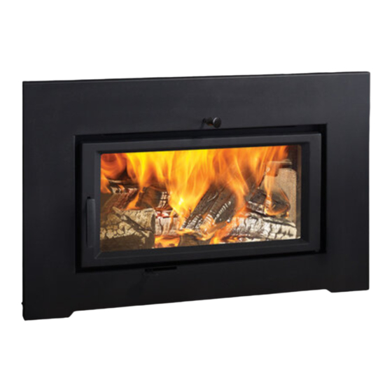
Pro Series
Wood
Fireplace
Insert
Owners & Installation Manual
French Manual: https://bit.ly/3vaoKti
Manuel en Français : https://bit.ly/3vaoKti
www.regency-fire.com
MODEL:
CI2700/HI500
Installer: Please complete the details on the back cover
and leave this manual with the homeowner.
Homeowner: Please keep these instructions for future reference.
Report #0219WN017S
FPI FIREPLACE PRODUCTS INTERNATIONAL LTD. 6988 Venture St., Delta, BC Canada, V4G 1H4
06.08.21
920-047f
Advertisement
Table of Contents

Related Manuals for Regency Fireplace Products Pro CI2700


Summary of Contents for Regency Fireplace Products Pro CI2700
- Page 1 Pro Series Wood Fireplace Insert Owners & Installation Manual French Manual: https://bit.ly/3vaoKti Manuel en Français : https://bit.ly/3vaoKti www.regency-fire.com MODEL: CI2700/HI500 Installer: Please complete the details on the back cover and leave this manual with the homeowner. Homeowner: Please keep these instructions for future reference. Report #0219WN017S FPI FIREPLACE PRODUCTS INTERNATIONAL LTD.
- Page 2 Thank-you for purchasing a REGENCY FIREPLACE PRODUCT. The pride of workmanship that goes into each of our products will give you years of trouble-free enjoyment. Should you have any questions about your product that are not covered in this manual, please contact the REGENCY DEALER in your area. Keep those REGENCY FIRES burning.
-
Page 3: Table Of Contents
table of contents Operating Instructions Copy of Safety Decal ..............4 Seasoned Wood ................29 Dimensions Operating Instructions ..............30 Draft Control ..................30 Dimensions - Contemporary Faceplate .........5 First Fire ..................30 Dimensions - Cast Faceplate and Offset Flue Collar .....6 Ash Disposal ..................31 Dimensions - Low Profile Faceplate ..........7 Fan Operation ................31 Dimensions - Cast Faceplate ............7... -
Page 4: Copy Of Safety Decal
safety decal SAFETY LABEL FOR CI2700 This is a copy of the label that accompanies your Regency Insert. We have printed a copy of the contents here for your review. NOTE: Regency units are constantly being improved. Check the label on the unit and if there is a difference, the label on the unit is the correct one. -
Page 5: Dimensions
dimensions DIMENSIONS - CONTEMPORARY FACEPLATE 28-7/8" (733mm) 18-1/2" (469mm) 40" (1016mm) 13-3/8" (340mm) 23-3/16" (589mm) 27-3/4" (750mm) ALL PICTURES / DIAGRAMS SHOWN THROUGHOUT THIS MANUAL ARE FOR ILLUSTRATION PURPOSES ONLY. ACTUAL PRODUCT MAY VARY DUE TO PRODUCT ENHANCEMENTS. CI2700/HI500 Wood Insert |... -
Page 6: Dimensions - Cast Faceplate And Offset Flue Collar
dimensions DIMENSIONS - STANDARD CAST FACEPLATE AND OFFSET FLUE COLLAR " 28-13/16'' (733mm) " 18-7/16'' (469mm) 18-13/16'' 3-11/16'' (478mm) (94mm) " 14-3/8'' (366mm) " 41-1/8'' (1045mm) 1045 26-3/8'' 23-5/16'' (670mm) 21-1/2'' (592mm) (546mm) 39'' (991mm) | CI2700/HI500 Wood Insert... -
Page 7: Dimensions - Low Profile Faceplate
dimensions DIMENSIONS - LOW PROFILE FACEPLATE 40'' 40" (1016mm) [1016mm] 26'' (660mm) 29'' 3/4'' 29" (737mm) (17mm) [737mm] DIMENSIONS - STANDARD CAST FACEPLATE 41-1/8'' 41-3/8" (1045mm) 1051mm 26-3/8'' (670mm) 39'' (991mm) Standard Cast Faceplate shown above Oversized Cast Faceplate Dimensions: 44" W x 31" H CI2700/HI500 Wood Insert |... -
Page 8: Dimensions - Standard Backing Plate
dimensions DIMENSIONS - STANDARD BACKING PLATE 44'' (1118mm) 3/4'' (19mm) 5/32'' (10mm) 29-7/8'' (759mm) 21-7/16'' (544mm) 20'' (508mm) 30-1/4'' (768mm) DIMENSIONS - OVERSIZED BACKING PLATE 48'' (1219mm) 5/32'' (10mm) 33-7/8'' (860mm) 21-7/16'' (544mm) 48'' (1219mm) 30-1/4'' (768mm) | CI2700/HI500 Wood Insert... -
Page 9: Installation
installation MASONRY AND FACTORY BUILT FIREPLACE CLEARANCES The minimum required clearances to combustible materials when installed into a masonry or factory built fireplace are listed below. Unit Adjacent Mantle ** Side Minimum Minimum To Top of Door Side Wall (to Top of Door) Facing Facing Hearth... -
Page 10: Installation Into A Masonry Fireplace
installation Draft is the force which moves air from the appliance INSTALLATION INTO A MASONRY CHIMNEY SPECIFICATIONS up through the chimney. The amount of draft in your FIREPLACE chimney depends on the length of the chimney, local Before installing, check and clean your chimney geography, nearby obstructions and other factors. -
Page 11: Installation Into A Factory Built Fireplace
installation 1. When installed in a factory built fireplace, a WARNING INSTALLATION INTO A FACTORY full stainless steel rigid or flexible flue liner is BUILT FIREPLACE mandatory, for both safety and performance Fire Risk. purposes. When a flue or liner is in use, the When lining air-cooled factory-built Regency inserts are constructed with the highest insert is able to breathe better by allowing a... -
Page 12: Installing Your Insert
installation INSTALLING YOUR INSERT Your insert is very heavy and will require two or three people to move it into position. The insert can be made lighter by removing the cast iron door by opening it and lifting it off its hinges. Be sure to protect your hearth extension with a heavy blanket or carpet scrap during the installation. Evaluate your minimum cavity opening. - Page 13 installation Upper Shield - center between 2 vertical pins C- Combustor- remove with pliers Tilt down and forward to ease removal. Access through the combustor opening from inside the firebox to rein- stall. Bypass plate may need centering before proceeding to next step. 11.
-
Page 14: Digital Catalytic Combustor Monitor
installation DIGITAL CATALYTIC COMBUSTOR MONITOR The CI2700/HI500 is equipped with a provision to accept a catalytic tempera- 3. Reinstall the plate removed in Step 1 and insert the temperature probe ture monitoring device. Please follow instructions below for the installation of through the plate and into the hole created by removing the bolt in Step 2. -
Page 15: Levelling Bolts
installation LEVELLING BOLTS 1. Use a 9/16" wrench to adjust the front leveling bolts located on the right and the left side of the firebox. Leveling Bolt Remove Bricks 2. Remove the three side bricks on each side then remove the corner bottom/side cut brick to gain access to the rear leveling bolts. You can adjust using a 9/16"... -
Page 16: Optional Cast Grill Installation
HI400 installation OPTIONAL CAST GRILL INSTALLATION OPTIONAL CAST GRILL INSTALLATION GLASS REMOVAL TO INSTALL OPTIONAL DOOR CAST GRILL 1. To remove the glass, remove the 4 retainer bolts (2 top and 2 bot- tom) highlighted in the diagram. 2. Carefully remove the glass and the gasket frame assembly. (Gasket frame assembly shown) 3. -
Page 17: Optional Backing Plate Installation
HI400/CI2600 installation BACKING PLATE INSTALLATION OPTIONAL BACKING PLATE INSTALLATION An optional backing plate is available in either a standard or oversized. 1. Slide the backing plate over unit. Line up flange on backing plate with flange on unit and secure with 2 screws from the underside as shown below. -
Page 18: Contemporary Faceplate Installation
installation CI2600 CONTEMPORARY FACEPLATE INSTALLATION CONTEMPORARY FACEPLATE INSTALLATION Remove unit door prior to installation of faceplate. 4. Attach the left and right side rails to the back of the bottom fascia panel Remove all contents from the package and lay out. using four 7/16’’... - Page 19 CI2600 installation 6. Apply the flat self adhesive gasket to the face of the unit just above the fan opening. Install the seal/cushion to line up with the top of the slide 8. Re-install bypass knob and door. out door. Gasket Final Install 7.
-
Page 20: Low Profile Faceplate Installation
CI2600 installation LOW PROFILE FACEPLATE INSTALLATION LOW PROFILE FACEPLATE INSTALLATION NOTE: If installing blower, optional Fan cassette must be installed prior at Remove unit door prior to installation of faceplate. this point. See fan installation instructions for details. Remove all contents from the package and lay out. If not installing blower—proceed to Step 6. NOTE: Bolts may be pre-installed on unit and will need to be removed prior to each step of the noted instructions. As a result, there may be spare bolts. - Page 21 CI2600 installation 8. Ensure the left and right side bolts on the top of the Low Profile Face- 6. A pply the flat self adhesive to the face of the unit just above the fan plate are spaced evenly. The spacing of these bolts is critical to ensure opening. Install the seal /cushion to line up with the top of the bottom of the faceplate slides into the brackets installed in Step 1. the low profile faceplate. NOT EXACTLY AS SHOWN Gasket 7/16" bolts on back of 7. G ently slide the bypass rod through the center hole within the fascia and Faceplate also guide the primary air control through the slot in the bottom of the fascia. Push the faceplate towards the unit, ensuring the bolts in Step 2 slide into the brackets installed in Step 1. 9. Tighten the 7/16’’ bolts on the back of the Flat Faceplate 10. Re-install bypass knob and door. Final Install CI2700/HI500 Wood Insert |...
-
Page 22: Cast Faceplate Installation
installation CI2600/ HI400 CAST FACEPLATE INSTALLATION CAST FACEPLATE INSTALLATION 4. Install two brackets (supplied with Faceplate) to the back of each side Remove unit door prior to installation of faceplate. Remove and lay out all contents from the faceplate package. panel with four 7/16’’... - Page 23 CI2600/ HI400 installation 7. Reinstall unit door (removed in Step 1), attach the left and right side rails to the back of the bottom fascia panel using four 7/16’’ bolts, slide each rail upward before tightening. (Rails may need to be bent slightly outward to get a good fit).
-
Page 24: Oversize Cast Faceplate Installation
installation CI2600/ HI400 OVERSIZE CAST FACEPLATE INSTALLATION OVERSIZE CAST FACEPLATE INSTALLATION 4. Remove 8-7/16" bolts in locations shown below and Install the left and Remove unit door prior to installation of faceplate. right of the fascia panels using four 7/16’’ bolts. Remove and lay out all contents from the faceplate package. - Page 25 CI2600/ HI400 installation 7. Apply self adhesive gasket to protect enamel surfaces from chipping. 5. Reinstall unit door (removed in Step 1), attach the left and right side Lift the top fascia panel up (use care as it is heavy) and slide down into rails to the back of the bottom fascia panel using four 7/16’’...
-
Page 26: Optional Fan/Blower Installation
installation CI2600 OPTIONAL FAN/BLOWER INSTALLATION OPTIONAL FAN/BLOWER INSTALLATION Installer: Please record unit serial number here before installing blower—serial number will not be visible after blower is installed. ______________________________ Serial No. 8. Tuck Power Cord to the bottom right hand side 4. - Page 27 CI2600 installation #8 Groun Lug Grounding Ground wire Lug Detail from fan Lockwasher Star washer Star washer Ground wire from power cord WARNING: Electrical Grounding Instructions This appliance is equipped with Blower/Fan Wiring Diagram a three pronged (grounding) plug for your protection against shock hazard and should be plugged CAUTION: Label all wires prior...
-
Page 28: Removable Door Handle
installation REMOVABLE DOOR HANDLE The CI2700/HI500 has a removable door handle that can be stored when not in use. All the faceplates have a storage hook on the left side that accommodates the handle. Hook Handle The cool to touch door handle is designed to be inserted from the bot- tom up and slide off when not held in place. -
Page 29: Operating Instructions
operating instructions SEASONED WOOD Whether you burn wood in a fireplace, stove or insert, good quality firewood is the key to convenience, efficiency and safety. Wet wood and pieces that are not the right size and shape for your wood burner can be frustrating, burn inefficiently and deposit creosote that can fuel a dangerous chimney fire. Good planning, seasoning and storage of the firewood supply are essential to successful wood burning. -
Page 30: Operating Instructions
operating instructions High Fire: Air control to far left. OPERATING INSTRUCTIONS FIRST FIRE Low Fire: Air control to far right. Med Fire: Air control slightly left of low fire set- When your installation is completed and inspected ting. you are ready for your first fire. With your unit now correctly installed and safety inspected by your local authority, you are now ready 8. -
Page 31: Ash Disposal
operating instructions 15. If you have been burning your stove on a low 4. A small hot fire is preferable to a large smoul- To achieve maximum efficiency and performance, draft, use caution when opening the door. After operate the fan in the low speed when the air control dering one that can deposit creosote within the opening the damper, open the door a crack, and is not more than ¼’’... -
Page 32: Safety Guidelines & Warnings
operating instructions SAFETY GUIDELINES & WARNINGS 11. Open the draft control fully for 10 to 15 seconds prior to slowly opening the DO NOT BURN: door when refuelling the fire. • Treated wood • Coal 12. Do not connect your unit to any air distribution duct. •... -
Page 33: Catalytic Combustor (Part # 106-534)
operating instructions CATALYTIC COMBUSTOR (PART # 106-534) ACHIEVING AND MAINTAINING CATALYST LIGHT-OFF: Step 1: Light the stove in accordance with instructions within this manual. There are some obvious signs of trouble that your inspection may reveal. Step 2: With smoke routed through the catalyst (by-pass closed) The temperature in the stove and the gases entering the combustor must be go outside and observe the emissions leaving the chim- raised to between 500F to 700F for catalytic activity to be initiated. -
Page 34: Combustor Assembly Removal/Replacement
maintenance COMBUSTOR ASSEMBLY REMOVAL / REPLACEMENT: If the combustor must be examined or replaced, follow this procedure: 1. Allow the stove to burn out and cool down. 2. Open the door and loosen the two 7/16” bolts -see locations below. Lid for Bypass Door TO REPLACE THE COMBUSTOR: First clean the combustor area and the area around the by-pass,use a... -
Page 35: Bypass Door Gasket Replacement
maintenance BYPASS DOOR GASKET REPLACEMENT 1. Remove bypass rod - turn counter clockwise. Bypass Rod D- Combustor- remove with pliers Tilt down and forward to ease removal. 2. The following parts must be removed to allow access and a positive connection. Primary Air Shield Combustor Flame Shield Combustor... -
Page 36: Maintenance
maintenance 4. Reinstall bypass plate. 5. Reinstall the Upper Shield removed in Step 2d. Ensure Upper Shield is centered in between 2 (two) vertical pins from front to back. When positioning the upper shield locate the vertical pins by feel. When the shield parts are in place - slide to the back. -
Page 37: Door Gasket
maintenance GLASS CLEANING DOOR GASKET GLASS REMOVAL Allow the stove to cool before removing or replacing If the door gasket requires replacement, 5/8" Only clean your glass window when it is cool. Your lo- glass. Remove the door from the insert and remove diameter material must be used. -
Page 38: Secondary Air Tube Removal/Installation
maintenance SECONDARY AIR TUBE REMOVAL / DOOR CATCH ADJUSTMENT INSTALLATION After a few fires, the door catch may require adjustment to renew a tight seal, as the door gasket will compress. Removal of a shim, shown in the diagram 1. Allow the stove to burn out and cool down, until cool to touch. below, will allow the catch to be moved closer to the door frame, creating a tighter seal. -
Page 39: Cast Bypass Top Plate Removal/Installation
maintenance CAST BYPASS TOP PLATE REMOVAL / FAN OPERATION INTO AUTO MODE INSTALLATION If fan will not come on in auto mode see the following possible causes and solutions: 1. Allow the stove to burn out and cool down, until cool to touch. Possible causes: 2. -
Page 40: Sweeping The Flue From The Top Down
maintenance Sweeping The Flue From The Top Down SWEEPING THE FLUE FROM THE TOP DOWN Note: The chimney system on this appliance cannot be cleaned 4. Close the door of the insert and the bypass rod from below. and sweep the flue from the top of the chimney IMPORTANT: It is imperative that the area around the exterior of the down into the bypass area. -
Page 41: Parts List
parts list MAIN ASSEMBLY Part # Description Part # Description 106-516 Flue Collar Assembly 106-517 Stove Top Assembly 106-062F Fork 106-917 Fan Assembly 106-534 Catalytic Combustor 106-525 Rear Panel Assembly 106-546 Contemporary Rail Assembly Left 106-038 Outer Shield L 106-547 Contemporary Rail Assembly Right 106-520 Black cast door Assembly... - Page 42 parts list 42 | CI2700/HI500 Wood Insert...
-
Page 43: Brick Layout
parts list BRICK LAYOUT 106-960 Brick Set - Complete CI2700/HI500 Wood Insert |... -
Page 44: Warranty
warranty Limited Lifetime Warranty FPI Fireplace Products International Ltd. (for Canadian customers) and Fireplace Products U.S., Inc. (for U.S. customers) (collectively referred to herein as “FPI”) extends this Limited Lifetime Warranty to the original purchaser of this appliance provided the product remains in the original place of installation. The items covered by this limited warranty and the period of such coverage is set forth in the table below. - Page 45 warranty All warranty claims must be submitted by the dealer servicing the claim, including a copy of the Bill of Sale (proof of purchase by you). All claims must be complete and provide full details as requested by FPI to receive consideration for evaluation. Incomplete claims may be rejected.
- Page 46 warranty Limitations of Liability: The original purchaser’s exclusive remedy under this warranty, and FPI’s sole obligation under this warranty, express or implied, in contract or in tort, shall be limited to replacement, repair, or refund, as outlined above. IN NO EVENT WILL FPI BE LIABLE UNDER THIS WARRANTY FOR ANY INCIDENTAL OR CONSEQUENTIAL COMMERCIAL DAMAGES OR DAMAGES TO PROPERTY.
- Page 47 warranty Product Registration and Customer Support: Thank you for choosing a Regency Fireplace. Regency strives to be a world leader in the design, manufacture, and marketing of hearth products. To provide the best support for your product, we request that you complete a product registration form found on our Web Site under Customer Care within ninety (90) days of purchase.
-
Page 49: Catalytic Combustor Coverage Warranty
NO LABOR WILL APPLY. All warranty claims must be sent to: Regency Fireplace Products By Authorized Regency Dealer * Prices subject to change. - Page 50 notes 50 | CI2700/HI500 Wood Insert...
- Page 51 CI2700/HI500 Wood Insert |...
- Page 52 Installer: Please complete the following information Dealer Name & Address: ______________________________________________ ___________________________________________________________________ Installer: ___________________________________________________________ Phone #: ___________________________________________________________ Date Installed: ______________________________________________________ Serial #: ____________________________________________________________ Regency is a trademark of FPI Fireplace Products International Ltd. Printed in Canada © Copyright 2021, FPI Fireplace Products International Ltd. All rights reserved.
Need help?
Do you have a question about the Pro CI2700 and is the answer not in the manual?
Questions and answers