
Related Manuals for Blackmagicdesign Videohub 12G


Summary of Contents for Blackmagicdesign Videohub 12G
- Page 1 April 2023 Installation and Operation Manual Blackmagic Videohub Blackmagic Videohub 12G Videohub Master Control Pro Universal Videohub Videohub Smart Control Pro Smart Videohub CleanSwitch 12x12 Blackmagic GPI and Tally Interface...
- Page 2 Please check our website at www.blackmagicdesign.com and click the support page to download the latest updates to this manual and Videohub software. Lastly, please register your Videohub when downloading software updates so we can keep you updated when new software is released.
-
Page 3: Table Of Contents
Contents Introducing Blackmagic Videohub GPI and Tally Interface Blackmagic Videohub Software Getting Started Blackmagic Videohub Setup Connecting Power Labeling Inputs and Outputs Connecting Video Setting Outputs to Cut Bus Mode Controlling your Videohub Creating Macros Switching a Route using the Built in Control Panel Button Mapping Shortcut Buttons... -
Page 4: Introducing Blackmagic Videohub
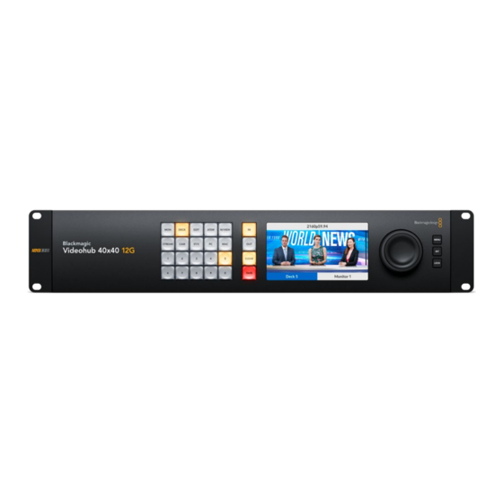
Introducing Blackmagic Videohub Your Blackmagic Videohub is part of a family of Videohubs designed for studios and facilities of any size. All Videohub models can be connected to an Ethernet network for external hardware control or by using Videohub Control software. Blackmagic Videohub 10x10 12G, 20x20 12G and 40x40 12G are 12G-SDI routers with a built in control panel and support Ultra HD 2160p60. - Page 5 Universal Videohub 288 and 72 are rack mounted modular 3G-SDI routers for larger studios and facilities where a greater amount of HD equipment is connected. Universal Videohub 288 Universal Videohub 72 Introducing Blackmagic Videohub...
- Page 6 Videohub Master Control Pro and Smart Control Pro are external hardware control panels that use the same filtering control available in Blackmagic Videohub 12G models. These units are designed to work with Universal Videohub 72 and 288, but can also be used to control any Videohub connected to the same Ethernet network.
-
Page 7: Getting Started
SD/3G/12G SDI IN SD/3G/12G SDI OUT When you first turn on a Videohub 12G model, the LCD will ask you to select your chosen language. Scroll through the languages using the search dial and press the ‘set’ button to confirm your selection. -
Page 8: Switching A Route Using The Built In Control Panel
Switching a Route using the Built in Control Panel Switching a route is as simple as selecting the destination output and then selecting a source input to route to it. Selecting the Source and Destination Press the ‘out’ button to enable the destination output selection. MENU DECK EDIT... -
Page 9: Shortcut Buttons
This utility is included in the free Videohub software available for download at the Blackmagic Support Center at www.blackmagicdesign.com/support We recommend installing the setup software and labeling your Videohub’s inputs and outputs, then returning to this section for information on how to use the shortcut buttons. -
Page 10: Using The Shortcut Buttons
Using the Shortcut Buttons After the inputs and outputs have been labeled, the shortcut buttons can use Videohub’s filtering to make faster selections. To use the shortcut buttons: Select the Destination Press the ‘out’ button to enable the destination selection. MENU STREAM COMP... - Page 11 Select the Source Press the ‘in’ button to enable the source selection. MENU STREAM COMP SWITCH ST/C M/VIEW CLEAR TAKE LOCK Press the shortcut button labeled ‘CAM’. DECK EDIT STREAM COMP SWITCH ST/C M/VIEW CLEAR TAKE TAKE The filter now makes all inputs available that includes CAM in their label, filtering out other equipment and then arranges them on the numbered pushbuttons in numerical order.
-
Page 12: Locking And Unlocking Routes
Locking and Unlocking Routes Locking and unlocking routes with your Blackmagic Videohub can be set easily using the integrated front panel. Press the ‘lock’ button to lock the currently selected output and you will see a lock indicator appear next to its name on the LCD. If you want to lock a different output: Press the destination button marked ‘OUT’. -
Page 13: Connecting Videohub To A Network
Connecting Videohub to a Network All Videohub models have an Ethernet port and can connect directly to your Ethernet network switch or a computer on your local area IP based network. This lets you control your videohub using Blackmagic Videohub Control software on a computer connected to the same network, or by using an external Videohub hardware control panel. -
Page 14: Configuring Network Settings
Configuring Network Settings Use your Videohub’s built in control panel and LCD to configure network settings. Your router will be visible to other computers and hardware panels and these devices can then control the unit remotely and make routing changes. To set the IP address using the front control panel: Press the ‘menu’... - Page 15 See the ‘SDI Interface Card’ and ‘Universal Videohub Interface Cards’ sections for more information on the different interface cards available for your Universal Videohub. Universal Videohub 288 Universal Videohub 288 Crosspoint Card This module contains the crosspoint processor for switching video routes and changing deck control ports.
- Page 16 Router Control Cable Remote router control is performed via 10/100Base-T Ethernet or serial. If router control is performed via Ethernet, the integrated Videohub Server is used. This means you only need to provide an Ethernet cable to connect Universal Videohub 288 to your Ethernet network switch. Third party router controllers can control Universal Videohub 288 via Ethernet, or as an RS-422 slave device, for router crosspoint switching.
- Page 17 Installing a Universal Videohub 288 Crosspoint Card Now that your Universal Videohub 288 has been mounted in a rack, it needs to be fitted with a crosspoint card. The crosspoint card is the brains of Universal Videohub and performs video route and deck control switching. Universal Videohub 288 Crosspoint cards are hot-swappable, meaning they are designed to be installed and removed while the Universal Videohub is running.
- Page 18 POWER OVERLOAD REF IN RS-422 CONTROL USB DIAGNOSTIC ETHERNET ALARM POWER OVERLOAD REF IN RS-422 CONTROL USB DIAGNOSTIC ETHERNET Status LED lights ALARM Reference In RS-422 router control USB 2.0 Ethernet router control Alarm GPI Handle Universal Videohub Status LEDs The status LEDs marked ‘alarm’, ‘power overload’...
- Page 19 Blackmagic Universal Videohub 288 Crosspoint has amber colored LEDs mounted inside the device that should only be visible when the heatsink is removed for development purposes. However, in some cases a dim amber light may be visible through the hole that has been drilled for the ‘alarm’ LED. This is not an error condition. A healthy Universal Videohub 288 Crosspoint should display the following: Red ‘alarm’...
- Page 20 Installing a Universal Videohub SDI Interface Card M A IN P O W + 1 2 V 8 0 The Universal Videohub Power Supply consists of a power card which is inserted into the Universal Videohub 288 and then connected to a 1 RU chassis located under the Universal Videohub 288 Universal Videohub Routers...
- Page 21 Installing a second Power Supply while Universal Videohub 288 is running If you wish to install a redundant or replacement power supply while Universal Videohub 288 is already running from a power supply, please carry out the installation procedure in the following order: Ensure that the new power supply is disconnected from any electrical source.
-
Page 22: Universal Videohub 72
Universal Videohub 72 Universal Videohub 72 is a medium-sized modular router ideal for growing facilities. It features an 18 card rack frame that can be filled with any combination of BNC SDI or optical fiber SDI interface cards. When fully populated with a crosspoint card, a power card, 18 SDI interface cards and 18 deck control cables, Universal Videohub 72 provides 72 SDI inputs, 72 SDI outputs, 72 bidirectional RS-422 deck control ports, reference input, redundant power supply options and powerful Videohub routing control software for Mac and Windows. -
Page 23: Universal Videohub
Router Control Cable Remote router control is performed via 10/100Base-T Ethernet or serial. If router control is performed via Ethernet, the integrated Videohub Server is used. This means you only need to provide an Ethernet cable to connect Universal Videohub 72 to your Ethernet network switch. Third party router controllers can control Universal Videohub 72 via Ethernet, or as an RS-422 slave device, for router crosspoint switching. - Page 24 Installing a Universal Videohub 72 Crosspoint Card Hold the crosspoint card in a vertical orientation by its two levers. The Ethernet port should be towards the bottom end of the card. Gently insert the card into its slot, ensuring the top and bottom edges follow the black guides.
- Page 25 MAIN POWER MAIN POWER +12V 800W +12V ALARM POWER OVERLOAD REF IN RS-422 CONTROL Status LED lights Reference In USB DIAGNOSTIC RS-422 router control ETHERNET USB 2.0 ALARM Ethernet router control POWER OVERLOAD REF IN Handle Universal Videohub 72 Crosspoint RS-422 CONTROL Universal Videohub Status LEDs The status LEDs marked ‘alarm’, ‘power overload’...
- Page 26 Blackmagic Universal Videohub 72 Crosspoint has amber colored LEDs mounted inside the device that should only be visible when the heatsink is removed for development purposes. However, in some cases a dim amber light may be visible through the hole that has been drilled for the ‘alarm’ LED. This is not an error condition. A healthy Universal Videohub 72 Crosspoint should display the following: Red ‘alarm’...
-
Page 27: Sdi Interface Card
If you have only partially populated your Universal Videohub 72 with interface cards, you might be able to power it with a single 150W power supply and preferably use a second power supply for failover redundancy. If you choose this option: Temporarily disconnect the second power supply and then check the Power Overload light on the crosspoint card after installing any cards. -
Page 28: Universal Videohub Interface Cards
Universal Videohub Interface Cards Universal Videohub SDI Interface Card MAIN POWER MAIN POWER +12V 800W +12V ALARM POWER OVERLOAD REF IN RS-422 CONTROL Activity light USB DIAGNOSTIC Output 1 2 3 4 Universal Videohub Deck Control Cable connector ETHERNET Input 1 2 3 4 Universal Videohub Optical Interface Card MAIN POWER MAIN POWER... -
Page 29: Universal Videohub Deck Control Cable
Tips for Connecting SDI cables The weight of copper-based SDI cables quickly adds up so it is advisable to use your rack to support the cables so that the full cable weight does not place undue stress on the BNC ports of your Videohub. This is particularly important with larger models of Videohub due to the weight of many SDI cables. -
Page 30: Smart Videohub Cleanswitch 12X12
Smart Videohub CleanSwitch 12x12 When you need to cleanly switch between video sources to monitors or directly to air, you will need timed or genlocked signals. If you cannot guarantee perfectly timed source signals but you still need to clean switch, then you can use Smart Videohub CleanSwitch 12x12 as this model features resynchronization on all inputs so you get perfect clean feeds. -
Page 31: Videohub Smart Control Pro
Videohub Smart Control Pro Videohub Smart Control Pro is a 1 rack unit mountable control panel with 48 backlit pushbuttons and Ethernet connectivity. When configured for a single SDI destination, such as a monitor or deck, the pushbuttons can instantly switch between 48 different SDI sources on the same Videohub router. When configured for multiple SDI destinations, destination buttons become gold, source buttons become white and the lower right button can be configured as a take button and illuminates red. -
Page 32: Connecting To An Ethernet Network
Connecting to an Ethernet Network In most facilities, Videohub is usually shared via an Ethernet network switch so it can be controlled by computers on the network as well as by Videohub control panels. Connect the control panel to the network as you would any Videohub router. MAIN POWER +12V ALARM... -
Page 33: Control Panel Button Diagnostics
Control Panel Button Diagnostics When power is first connected to a Videohub control panel, all the buttons will display their test lights in the following sequence: red, green, blue and white. The top left button of a Videohub control panel indicates its network status using the following diagnostic display: Pink Flashing Light Unit is attempting to acquire an IP address. -
Page 34: About Routing Levels
About Routing Levels If your Videohub does not feature RS-422 remote deck control, Videohub Master Control will always show ‘SDI’ on its LCD and you don’t need to read anything more about routing levels. If your Videohub does include RS-422 remote deck control ports, you can use the LEVEL button on Videohub Master Control to reduce the list of sources and destinations by routing level. -
Page 35: How To Select Sources And Destinations
Choose this routing level if you want to reduce the list of video equipment to all devices with RS-422 deck control. This will list sources and destinations by the names of their RS-422 remote ports, regardless of whether there are any associated SDI ports and regardless of whether any associated SDI ports have matching labels or not. - Page 36 Type in the destination port number using the numeric pushbuttons. Each button will flash gold once as you press it. The destination will be displayed on the LCD. If you make a mistake, press the white ‘clear’ button and retype the port number. Press the source button marked ‘SRC’.
- Page 37 Selecting Units using Customizable Buttons and the Scroll Wheel If you have customized the Videohub port labels, you can use the customizable buttons and scroll wheel together to find a short list of sources and destinations. This method is fast and intuitive because you only have to scroll through a short list of equipment and you don’t have to remember any port numbers.
- Page 38 Selecting Units using Numeric Buttons and the Scroll Wheel If you have customized the Videohub port labels with numbers, you can use the numeric buttons and scroll wheel together to find a short list of sources and destinations. This method is fast and intuitive because you only have to scroll through a short list of equipment and you don’t have to remember any port numbers.
- Page 39 Press the destination button marked ‘DEST’. The destination field will be highlighted blue on the LCD. If your Videohub router has RS-422 remote control, press the LEVEL button until you have set the appropriate routing level for your equipment. Otherwise you can skip this step. Press a button you have customized for a type of destination equipment, e.g., VTR.
-
Page 40: Using Videohub Smart Control Pro As A Cut-Bus Controller
Press and hold the gold destination button until a lock icon appears in the destination field of the LCD. Press ‘destination’ again to return Videohub Master Control to its idle state and the destination field will revert to gray. The destination field shows a lock icon if the destination is locked. -
Page 41: Using Videohub Smart Control Pro As An Xy Controller
Using Videohub Smart Control Pro as an XY Controller If Videohub Smart Control Pro has been configured as an XY controller, destination buttons light up gold and source buttons light up white. When working with multiple destinations, always select a destination button before selecting a source button. To change routes: Select a gold destination button and it will light up brightly to distinguish itself from the other destination buttons. -
Page 42: Labeling Pushbuttons
Labeling Pushbuttons Videohub Master Control Pro, Videohub Smart Control Pro and Videohub 12G models have removable pushbuttons that provide access for labeling. Included with the software installer is a ‘Videohub control labels’ folder containing a PDF template file. Fill out and print the PDF file labels, then cut out the squares to be inserted into the buttons. -
Page 43: Using The Control Panel
LOOP OUT REF IN RS-422 CNTRL ETHERNET SD/HD/3G/6G-SDI IN HDMI OUT 6G-SDI OUT HD-SDI OUT Blackmagic MultiView 16 SOLO VIEW MENU LOOP OUT REF IN RS-422 CNTRL ETHERNET SD/HD/3G/6G-SDI IN HDMI OUT 6G-SDI OUT HD-SDI OUT You can operate Blackmagic MultiView 16 using the built in control panel, or remotely via Blackmagic MultiView 16 Ethernet or serial connections if mounted in a rack where you don’t have access to the front SOLO... - Page 44 LOOP OUT REF IN RS-422 CNTRL Control Buttons ETHERNET SD/HD/3G/6G-SDI IN HDMI OUT 6G-SDI OUT HD-SDI OUT Blackmagic MultiView 16 SOLO VIEW MENU SRC and VIEW Use the ‘src’ and ‘view’ buttons to open the ‘source’ and ‘view’ settings. These buttons let you select which input source you want to display on a desired view.
-
Page 45: Gpi And Tally Interface
SRC, VIEW and SET Press the source and view buttons on the control panel to open the source and view settings. To adjust settings, use the number buttons or the rotary knob, LOOP OUT then press ‘set’ to confirm. REF IN RS-422 CNTRL The source and view settings screen highlights which setting you are currently... -
Page 46: Blackmagic Videohub Software
Blackmagic software includes three important software applications used to configure and control your Videohub and Videohub hardware panels. Download the Blackmagic Videohub Software from the Blackmagic Support Center at www.blackmagicdesign.com/support Blackmagic Videohub software includes the following applications: Blackmagic Videohub Setup. This is an administration utility for changing settings, configuring your Videohub and updating the unit’s internal software. -
Page 47: Labeling Inputs And Outputs
Labeling Inputs and Outputs The ‘inputs’ and ‘outputs’ tab lets you change the labels for all your source inputs and destination outputs. To label a source and output: Click in a source or destination’s text field. Type a new name. Press the return key on your computer keyboard to move to the next field, or simply click in the next text field to select it. -
Page 48: Setting Outputs To Cut Bus Mode
NOTE Port labels on an IP Videohub cannot be edited as these labels derive from the connected IP Video devices. The labels are stored on the connected Videohub and are also visible on the other control panels connected to your network. Setting Outputs to Cut Bus Mode In the output settings you will notice checkboxes next to each output. -
Page 49: Button Mapping
To activate a macro, simply press the macro button on the panel and then press ‘take’ to confirm the switch. Macros let you perform multiple simultaneous routes Button Mapping The labeled shortcut buttons on your Videohub’s control panel are used to select groups of equipment when changing routes. -
Page 50: Setup Settings
The software version is displayed so you can check it against the latest version on the Blackmagic Design support center at www.blackmagicdesign.com/support Video Monitoring When video monitoring is enabled, the LCD will show a preview of the source currently routed to a destination. -
Page 51: Updating Your Videohub
Network The network settings let you set the unit to use DHCP for automatic network connection, or static IP if you need to manually set an IP address. The network settings can be changed when your Videohub is connected to a computer via USB. To help limit the potential for accidental administration changes, Blackmagic Videohub Setup can be set to only allow users to make settings changes via USB. -
Page 52: Blackmagic Videohub Control
Blackmagic Videohub Control Using Blackmagic Videohub Control provides a fast and intuitive way to view and switch between multiple sources and destinations remotely. Videohub Control is easy to use because it operates on a single video output at a time. Selecting a destination or output pushbutton shows which source or input is connected to it by illuminating the source pushbutton. -
Page 53: Adding Pushbuttons
Adding Pushbuttons Click on the settings gear icon and then select ‘edit buttons’. Click on the ‘add’ button and choose whether to add a source or destination pushbutton. The ‘set button’ window appears and allows you to set the SDI source or destination, RS-422 deck control and icon for the pushbutton. -
Page 54: Blackmagic Videohub Control At A Glance
Blackmagic Videohub Control at a Glance Title Bar shows Use TAKE Videohub type Sources Area Search Scrollbars indicate not all pushbuttons are visible Destinations Area Search List View Settings Divider Bar Highlighted Pushbuttons Reveal Source Pushbutton View denote paired connections Click and drag the window edges to resize Blackmagic Videohub Control to fit your screen size. - Page 55 Edit Buttons Add a source or destination pushbutton. Allows you to set the SDI source or destination, deck control and the Edit icon for the selected pushbutton. Lock a destination to avoid accidentally changing the video source which is routed to that destination. If you click on a pushbutton that’s Lock and Unlock locked, the Lock button changes into an Unlock button.
- Page 56 Set Button The Set Button window allows icon selection, source or destination selection and deck control configuration. Moving Select the Settings button and then select “Edit Buttons”. Click and drag the Pushbuttons pushbutton to a new position. Viewing and Switching Routes Viewing Routes In order to see which video source has been routed to a video destination, such as a monitor, press the button in the destinations panel to make the button...
- Page 57 You can also lock one or multiple destinations via the edit buttons page. Shift click the destination pushbuttons you wish to lock and click the lock button. If you select a mixture of locked and unlocked pushbuttons, you will have the option to lock the unlocked pushbuttons. Locking a route between an input and an output also locks the RS-422 deck control connection between the two devices to avoid other users accidentally seizing the deck control belonging to the video source.
- Page 58 Serial Control Settings Third party router controllers can control Videohub with RS-422 serial connections. If controlling Videohub via RS-422, set the ‘Leitch protocol’ switch to: ͽ ‘Leitch client’ if the Videohub is to act as a client of a connected control panel and to listen and respond to the control panel button presses.
- Page 59 For this reason, we recommend configuring the pushbuttons with a mouse. Once the Videohub pushbuttons have been configured, it will be easy to use a finger to select and route, inputs and outputs, by tapping on Videohub pushbuttons. Touchscreens work a little differently to a computer mouse but provide the fastest and easiest way to work with the Videohub Control interface and so are highly recommended.
- Page 60 The bottom-right source button is reserved by the Videohub app itself and cannot be configured. This is because if a destination pushbutton is connected to a source that does not appear in the sources panel, the source will automatically appear in the bottom-right pushbutton.
- Page 61 In order to see which video source has been routed to a video destination, tap a destination button and the associated video source button will illuminate Locking and Unlocking Routes Locking a destination avoids accidental changes of the video source being routed to that destination.
- Page 62 Installing the Videohub Software on iPad The Videohub software for iPad can be downloaded using your Apple ID account. To download the Videohub iPad software through your iPad: Tap the ‘app store’ icon. Tap the ‘search’ field at the top of the screen and enter ‘Videohub’. Tap on the ‘get’...
-
Page 63: Controlling Blackmagic Multiview 16
Ensure Blackmagic MultiView 16 has the latest internal software installed and you are running the latest version of Videohub Control. You can download the latest updates from the Blackmagic Design support center at: www.blackmagicdesign.com/support Power your Blackmagic MultiView 16. Plug Blackmagic MultiView 16 into your computer via Ethernet. - Page 64 For more information on how to use Blackmagic MultiView 16 with Blackmagic Videohub Control software, refer to the Blackmagic MultiView instruction manual. You can find the latest manual and product updates at the Blackmagic Design support center at: www.blackmagicdesign.com/support Use the rotary knob or the number buttons on Blackmagic MultiView 16’s control panel to assign values...
-
Page 65: Videohub Hardware Panel Setup
Videohub Hardware Panel Setup When you launch Blackmagic Videohub Hardware Panel Setup, any Videohub control panels discovered on the network will be listed in the Videohub Control Panels pane next to an Ethernet network icon. If several Videohub control panels are listed, but you don’t know which one is which, select one of them and then press Identify. - Page 66 The Blackmagic Videohub Hardware Panel Setup automatically searches your network for any Videohub control panels You will also need to complete the IP details for the remote Videohub that you wish to control with your Videohub control panel. The remote Videohub is the Videohub Server. This could refer to a Videohub Server computer or an integrated Videohub Server onboard a Videohub model such as Smart Videohub 20x20.
-
Page 67: Configuring Videohub Master Control Pro
If you are setting up hardware panel control for an IP Videohub, enter the host computer’s IP address in the ‘remote Videohub IP’ setting field. The Videohub server shares the same IP address with the host computer. Add Videohub Control If you already know the IP address of a Videohub control panel but it hasn’t automatically appeared in the Videohub Control Panels pane, you can add the unit manually. -
Page 68: Configuring Videohub Smart Control Pro
Creating Button Labels 21 of the buttons can be labeled within the control utility to provide fast selection of common equipment types such as cameras, VTRs and monitors. Any of these 21 buttons can also be configured as macro buttons. If you haven’t done so already, you should standardize the port labels on your Videohub router before labeling any buttons on your Videohub control unit. - Page 69 Cut-Bus Configuration Drag the Number of Destinations slider to 1. Click on the Destination button. In the Router SDI Out A field, enter the number of the Videohub output port to which the destination device is connected. If your destination device requires dual link SDI, you will need to enter an output port number in the Router SDI Out A &...
- Page 70 Number of Macros Macros allow you to make up to 16 crosspoint routing changes simultaneously with a single button press. Drag the Number of Macros slider to enable up to 10 macro buttons. As you increase the number of macro buttons, there will be a matching decrease in the number of available source buttons.
-
Page 71: Configuring Gpis
Backlight Adjust the backlight slider to vary the brightness of the backlit buttons as desired. Enable Backlight Destinations Only if you wish to disable the backlighting of the white source buttons. Configuring GPIs The GPI and Tally Interface has 8 GPIs that provide crosspoint switching. In the example on the left, if GPI 1 detects a contact closure it will switch Input 12 on your Videohub to Output 1. -
Page 72: Configuring Tally
Momentary Hold Video Select this option if you want the output to return to the previous input after you let go of the switch or joystick control on your CCU. For example, when you press and hold your switch, Input 13 might be previewed, but will return to displaying Input 12 on your monitor once you release the switch. - Page 73 Sometimes it can get confusing to know which GPI and Tally Interface you are working with when you have several connected. Select the GPI and Tally Interface in the Videohub Control Panels pane and click the Identify button. The LED next to the Ethernet IN port on the selected device will light up.
- Page 74 Press the + (add device) button and enter the IP address of a GPI and Tally Device you want to add. Press the Identify button to activate the LED on a selected GPI and Tally Interface. Setting up the GPI and Tally Interface The GPI and Tally Interface is configured using the Videohub Hardware Panel Setup.
- Page 75 GPI and Tally Interface connected via USB If you do not know the IP address of your Videohub: Connect the Videohub to your computer via USB. Launch the Videohub software and click on Videohub Server Preferences. Note down the IP address in the Remote Videohub IP address field. Enter a GPI and Tally Name and the IP address of the Videohub you want to connect to Videohub Hardware Panel Setup...
-
Page 76: Developer Information
Developer Information Blackmagic Videohub Ethernet Protocol v2.3 Summary The Blackmagic Videohub Ethernet Protocol is a text based protocol that is accessed by connecting to TCP port 9990 on a Videohub Server. Integrated Videohub Servers and Videohub Server computers are supported by the protocol. The Videohub Server sends information in blocks which each have an identifying header in all-caps, followed by a full-colon. - Page 77 This example is for the Smart Videohub which is a 16x16 router. If the Videohub Server has no device connected, the block will simply be: VIDEOHUB DEVICE:↵ Device present: false↵ ↵ If a device is present, but has an incompatible firmware, the status reported will be: VIDEOHUB DEVICE:↵...
- Page 78 The next three blocks describe the routing of the output, monitoring and serial ports. VIDEO OUTPUT ROUTING:↵ 0 5↵ 1 3↵ … ↵ VIDEO MONITORING OUTPUT ROUTING:↵ 0 7↵ 1 8↵ … ↵ SERIAL PORT ROUTING:↵ 0 12↵ 1 11↵ …...
- Page 79 1 U↵ … ↵ MONITORING OUTPUT LOCKS:↵ 0 U↵ 1 U↵ … ↵ SERIAL PORT LOCKS:↵ 0 U↵ 1 U↵ … ↵ Videohubs with processing units (only the Workgroup Videohub) send an extra lock block: PROCESSING UNIT LOCKS:↵ 0 U↵ 1 U↵...
- Page 80 1 BNC↵ … ↵ VIDEO OUTPUT STATUS:↵ 0 BNC↵ 1 BNC↵ … ↵ SERIAL PORT STATUS:↵ 0 RS422↵ 1 RS422↵ … ↵ Status Updates When any route, label, or lock is changed on the Videohub Server by any client, the Videohub Server resends the applicable status block, containing only the items that have changed.
- Page 81 After a positive response, the client should expect to see a status update from the Videohub Server showing the status change. This is likely to be the same as the command that was sent, but if the request could not be performed, or other changes were made simultaneously by other clients, there may be more updates in the block, or more blocks.
-
Page 82: Videohub Rs-422 Protocol
Requesting a Status Dump The client may request that the Videohub Server resend the complete state of any status block by sending the header of the block, followed by a blank line. In the following example, the client requests the Videohub Server resend the output labels: OUTPUT LABELS:↵... - Page 83 Function Ground Tx- (Data sent by router) Rx+ (Data received by router) Ground NC (No connect) Ground Tx+ (Data sent by router) Rx- (Data received by router) Ground Videohub RS-422 Router Control DB9 pin connections. Pin No. Function Pin 1 TX + Pin 2 TX -...
- Page 84 Global Commands All pass-through commands are preceded by an symbol and a space. The following client commands are supported: disable status reporting Status reporting is disabled by default. enable status reporting Status reporting is enabled. reset routing table @ Z: Routing is reset so that the first source is routed to all destinations.
-
Page 85: Saving And Loading Labels With Telnet In Mac Os
Saving and Loading Labels with Telnet in Mac OS Normally you would use Blackmagic Videohub Setup to save and load labels between different Videohub routers and to backup your videohub settings. However, if for any reason you wish to use the Terminal, the instructions below let you save and load router label configurations via the Terminal. -
Page 86: Saving And Loading Labels With Telnet In Windows
Loading Labels Open the Terminal application with is located within the Applications > Utilities folder. Type in “telnet” and a space followed by the IP of your Videohub, then another space and “9990”, which is the default port number. For example type: telnet 192.168.25.253 9990. The Protocol Preamble screen will appear. - Page 87 Right click in the PuTTY session to paste the copied section and press “Enter” twice. PuTTY will respond with “ACK” and Videohub will update the input labels. Open the “output labels” text file in your text editing program and copy the OUTPUT LABELS: text.
-
Page 88: Replacing A Fan In Universal Videohub
Replacing a fan in Universal Videohub Each fan is designed to be replaced without needing to switch off power to Videohub. Locate the fan tray at the base of the unit. Using a number 01 Phillips head screwdriver, remove the left and right screws from the fan tray. -
Page 89: Help
Blackmagic Design online support pages The latest manual, software and support notes can be found at the Blackmagic Design support center at www.blackmagicdesign.com/support. Blackmagic Design Forum Another useful resource is the Blackmagic Design Forum. The forum is a place to find similar questions and quick solutions from either Blackmagic staff or fellow customers with extensive knowledge. -
Page 90: Regulatory Notices
Regulatory Notices Disposal of Waste of Electrical and Electronic Equipment Within the European Union. The symbol on the product indicates that this equipment must not be disposed of with other waste materials. In order to dispose of your waste equipment, it must be handed over to a designated collection point for recycling. -
Page 91: Safety Information
Safety Information For protection against electric shock, the equipment must be connected to a mains socket outlet with a protective earth connection. In case of doubt contact a qualified electrician. To reduce the risk of electric shock, do not expose this equipment to dripping or splashing. Product is suitable for use in tropical locations with an ambient temperature of up to 40 Ensure that adequate ventilation is provided around the product and that it is not restricted. -
Page 92: Warranty
Warranty Limited Warranty Blackmagic Design warrants that Videohub routers will be free from defects in materials and workmanship for a period of 36 months from the date of purchase excluding connectors, cables, cooling fans, fiber optic modules, fuses, keyboards and batteries which will be free from defects in materials and workmanship for a period of 12 months from the date of purchase.
Need help?
Do you have a question about the Videohub 12G and is the answer not in the manual?
Questions and answers