Siemens 3AH Series Instructions Manual
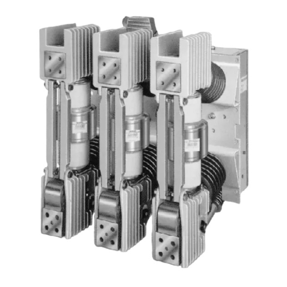
Vacuum circuit breaker operator module
Hide thumbs
Also See for 3AH Series:
- Instructions, installation, operation, maintenance (33 pages) ,
- Installation operation & maintenance (20 pages)

Related Manuals for Siemens 3AH Series


Summary of Contents for Siemens 3AH Series
- Page 1 S IEMENS Vacuum Circuit Breaker Instructions Installation Operator Module Operation Maintenance Type 3AH SGIM-99180 4.16kV to 38kV Medium-Voltage Equipment...
- Page 2 It does not relieve the user of responsibility to use sound practices in a pplication, installation, operation, and maintenance of the e q uipment purchased. Siemens reserves the right to make cha nges in the specifications shown herein or to make im provements at any time without notice or obligations.
-
Page 3: Table Of Contents
Vacuum Circuit Breaker Operator Module Table of Contents Table of Contents Maintenance ............................Introduction and Maintenance Intervals ........19 Table of Illustrations .............. Recommended HandTools ............19 Introduction and Safety Recommended Maintenance and Lubrication ......19 ............Introduction ................ - Page 4 Vacuum Circuit Breaker Operator Module Table of Illustrations Tables Figures Front Panel Controls of Circuit Breaker Figure 1 Table 1 Maintenance Tasks ..........20 and Manual Charging of Closing Spring ..... 5 Table 2 Maintenance and Lubrication Intervals Figure 2 Vacuum Circuit Breaker Module ......
-
Page 5: Introduction And Safety
Dangerous Procedures In addition to other procedu res described in th is manual as Contact the nearest Siemens representative if a ny a d d itional dangerous, user personnel must adhere to the following: information is desired. -
Page 6: Receiving, Handling And Storage
3. Notify the Siemens Sales office immed iately of any ship Outdoor Storage - Outdoor storage is not recommended. ment damage. -
Page 7: Installation Checks And Initial Functional Tests
Installation Checks and Initial FunctionaiTests Introduction This section provides a description of the inspections, checks and tests to be performed on the circuit breaker module only. Inspections, Checks and Tests without Control Power Vacuum circuit breakers are normally sh ipped with their primary contacts open and their springs d ischa rged. -
Page 8: Vacuum Interrupter/Operator Description
Vacuum Interrupter/Operator Description Introduction The Type 3AH vacu u m circuit breaker operator is intended connect the circuit breaker to both primary and control for application in a d rawout truck for use in medium voltage power and an operator housing. In a typical installation in a drawout truck, insulating barriers a re located between the metal-clad switchgear. -
Page 9: Vacuum Interrupters
Vacuum Interrupter/Operator Description Rxed C ontact current Ceramic lnsiJator --� FIXed Contact Moving Ceranic Metal Figure 4. Vacuum Interrupter/Operating Mechanism Module Guide lower primary disconnect pad provisions, to perform th e connection to the switchg ear. Moving contact Current Connectkln ---- -- -' Bolting hardware is M 1 2 1.75 grade 8.Torque M 1 2 bolts to 52 ft/lbs (70 N m ) . -
Page 10: Construction (Figures 1. 2. 5. 6A,And 6B)
Vacuum Interrupter/Operator Description Current-Path Assembl y (Figure 5 ) Construction (Figures 1 , 2, 5, 6a and 6b) T h e current-path assembly consists of t h e pole h e a d , the Each of the circuit breaker poles a re fixed to the rear of the stationary contact, and the moving contact, which is con... -
Page 11: Figure 6A Stored Energy Operating Mechanism
Vacuum Interrupter/Operator Description 62.5 50.3 62.6 50.5 50.2 62.1 62.2 55.1 50.4.1 62.8.1 63.7 50.2 Charging mechanism gear box Operation counter Jack shaft 50.3 Charging flange Operator housing 63.1 Lever - phase C 50.3.1 6 1.8 Shock absorber 63.5 Lever - phase B Driver 50.4 Spring charging motor 88... -
Page 12: Figure 6B Stored Energy Operating Mechanism
Vacuum Interrupter/Operator Description 64.2 Figure 6b. Stored Energy Operating M echanism (Circuit Breaker Shown in Closed Positio n ) 64.2 Trip latch pawl Open pushbutton 64.3 Lever 62.8 Trip free cou pling rod Pawl roller 64.3.1 62.8.1 Spring return l atch Trip free coupling link (Draw bar) 62.8.2... -
Page 13: Construction
Vacuum Interrupter/Operator Description As the closing spring d ischarges, th e ch arging shaft (62.1 ) is Construction The essential parts of the operating mecha nism are shown turned by crank (62.2). The cam d isc (62.3) at the other e n d in Figures 6a and 6b. -
Page 14: Close Coil, 52Src
Vacuum Interrupter/Operator Description Insulati ng coupler 62.3 Cam disc Jack shaft Charging flange 50.3 62.5 Lever 63.1 Lever-phase C 50.3.1 Driver 62.5.1 Pawl roller 63.5 Lever-phase B Close pushbutton 62.5.2 Close l atch pawl 63. 7 Lever-phase A 53.1 "Close coil, 52SRC" 62.6 Drive lever Opening spring... - Page 15 Vacuum Interrupter/Operator Description 62.5.2 Close latch pawl 62.8.6 Interlock lever-push rod 64.2.1 Trip latch pin 62.8.1 Spring return latch 62.8.7 Interlock lever-actuator 64.2.2 Latchi n g pawl release lever 62.8.2Trip free d raw bar 62.8.8Trip free actuator Lever 64.3 62.8.3Trip free lever 63.5 Lever-phase 64.3.1 Jack shaft pawl...
- Page 16 Vacuum Interrupter/Operator Description Elementary Diagram (Figure 10) A typical elementary diagram is shown in Figure 10 for DC motor, close and trip operation. Symbd List Sprirg Chargirg Motor 52SRC CloseCol S'Z'( C losirg Relay ( Ant�purrp ) Trip Coi l Spri rg Charged it Switch Mecharlcallnte�ock...
-
Page 17: Indirect Releases (Secondary Shunt Release (Dual Trip) (52T1) Or Undervoltage (27))
Vacuum Interrupter/Operator Description Close coil ( 52SRC) The close coil (3AY1 510) is a standard component of the 11 21 25 27 circuit breaker which is used to unlatch the stored energy of the closing spring and thus close the circuit breaker elec trically. -
Page 18: Capacitortrip Device
Vacuum Interrupter/Operator Description absorber is to l imit overtravel and rebound of the vacuum On the undervoltage release 3AX1103, the latch (25) is held interrupter movable contacts during the conclusion of an by the locking pin ( 2 1 ) as long as the armature (9) is ener opening operation. -
Page 19: Maintenance
Regardless of the length of the maintenance and l ubrication A WAR NING interval, Siemens recommends that circuit brea kers should be inspected and exercised annually. Failure to properly maintain the equipment could result in death, serious injury or product failure, and can prevent For the safety of ma intenance personnel as wel l as others successful functioning of connected apparatus. -
Page 20: • Checks Of The Pri M A Ry Power Path
36kA (250MVA) covered sufficiently for the Purchaser's pu rposes, the matter 10 years/10,000 operations 15 kV 23kA (500MVA) should be referred to the local Siemens sales office. 10 years/10,000 operations (See Note) All Others All Others DANGER Note: For circuit breaker rati ngs other than 5kV - 250MVA and 1 5kV - 500MVA overh a u l is required at 10,000 operations The use of unauthorized parts in the repair of the equip... -
Page 21: Figure 15 Operator Lubrication Points
Maintenance � Anderol 732 or Klueber lsoflex Klueber lsoflex, Anderol 732 or Beacon #325 Figure 1 5. Operator Lubrication Points... -
Page 22: Fastener Check
Maintenance Fastener Check Inspect all fasteners for tightness. Both lock-n uts a n d retain ing rings are used. Replace a ny fasteners that a ppear to have been frequently removed and replaced. Varnum Manual Spring Charging and Contact Erosion Checks I nterrupter Perform the M a nu a l Spring Charging Check conta ined in the section describing the Installation Check and I n itia l Function... -
Page 23: Electrical Control Checks
Maintenance Electrical Control Checks Table 3. Typical Vacuum Interrupter Contact Life Expectancy The electrical controls of the circuit breaker should be checked d u ring inspections to verify a bsence of a ny me Curve Number Rated Max. Interrupting Rated cha nical damage, and proper operation of the a utomatic Voltage Class... - Page 24 Mai n tenance 100,000 100,000 &lPOO 50,000 20POO 20,000 .!1! 10,000 10,000 >- 5poo 5,000 "" -� 2POO 2,000 � 1 POO 1 .000 � "iii ·m &lO -� 40 &l 20 I I 5o 25 36 loo d GraJil ' A' Break i ng c urrent (sym.
-
Page 25: Electrical Close And Trip Check ( Control Power Required)
Maintenance A vacuum interrupter may be assumed to be intact if it Electrical Close and Trip Check ( Control Power Required) shows the following cha racteristics: A check of the circuit breaker control circu its shall be performed . This check is made with the circuit breaker An appreciable closing force has to be overcome when lever energ ized by control power either from the switchgear or an 18). -
Page 26: Vacuum Integrity Test Procedure
Mai n ten ance Prinary Contact Res stance Test Step 2 alingC oupleq PrimarY Contac t (Operating Posti:ln) Closed Positi:l n - �nsulated C ol-Per Dl!connected) ( 48) (Lo.vered Position) prinary contact (Se p 2) Open Position - (Forced by tlar&.�al Open Pressure) Figure 18. -
Page 27: Insulation And Contact Resistance Test Procedure
Maintenance Insulation and Contact Resistance Test Procedure Inspection and Cleaning of Circuit Breaker Insulation 1. Observe safety precaution listed in the danger and caution 1. Perform the Spring Discharge Check on the circuit breaker advisories for the Vacuum Integrity Check tests. after all control power is removed. -
Page 28: Overhaul
( Loctite #222, Siemens part charts at the end of this section, provide maintenance per 1 5-1 33-281-007) and primer ( Loctite primerT, Siemens sonnel with a g u i d e to identifying a n d correcting possible part 1 5- 1 33-28 1-005) . -
Page 29: Figure 19 Vacuum Interrupter Replacement Illustration
Overhaul 3 1 .2 30 - - -i --t it- .. Figure 1 9. Vacu um Interrupter Replacement Illustration 1 6 .1 Post insulator 29.1 Flexible con nector Pole bottom Pole head 29.2 Terminal clamp Insulating coupler U pper connection pad Vacuum interrupter 48.5 Strut... - Page 30 Overhaul 1 .3 Withdraw pin (48.5) from insu lating coupler (48) a n d 2. I n stalling a Vacuum Interrupter levers (48.6) . NO T E: Replacement vacuum interrupter (30) will be re 1.4 Remove coupling pin from the eye bolt (36.3) ceived from the factory with an eyebolt (36.3) in place, adjusted and torq ued to specific requ irements.
-
Page 31: Hydraulic Shock Absorber
Overhaul 2.4 Fasten the pole head to the post insulator ( 1 6.1 ) 3. Checking the Contact Stroke "finger tight" using hex head bolt, lock washer a n d flat washer. 3.1 Open the circuit breaker. 2.5 Attach struts (28) to the upper pole su pport (20), 3.2 Free insulating coupler (48) by removing pin (48.5). -
Page 32: Maintenance Andtroubleshooting
2.The vacu u m interrupter type designation is labeled on the vacu u m interru pter. vac u u m interrupter does not match rating, contact the nea rest Siemens representative. you need assistance achieving adjustments, contact the nea rest Siemens representative. - Page 33 Maintenance andT rou b leshooting Troubleshooti ng Table Possible Causes and Remedies Problem Symptoms Circuit breaker fails to close Closing spring will not automatically 1 . Secondary control circuit is de- charge energ ized or control circuit fus- esare blown. Check and energize or replace if necessary 2.
- Page 34 Maintenance andTroubleshooting (continued) Trou bleshooti ng Table Possible Causes and Remedies Problem Symptoms N uisance or false close Electrical problem 1. N u isance or false closing signal to secondary discon nect contact A2. Check relay logic. Correct as req u ired. 2 .
-
Page 35: Appendix
Appendix Table A-1 a Type 3AH Circuit Breaker Ratings (Historic "Constant MVA" Rating Basis) These ratings are in accordance with the following standards: ANSI C37.04-1979 Standard Rating Structure for AC High-Voltage Circuit Breakers Rated on a Symmetrical Current Basis ANSI C37.06-1987 AC High-Voltage Circuit Breakers Rated on a Symmetrical Current Basis- Preferred Ratings and Related Required Capabilities ANSI C37.09-1979 Standard Test Procedure for AC High-Voltage Circuit Breakers Rated on a Symmetrical Current Basis... - Page 36 Appendix Table A-1 b Type 3AH Circuit Breaker Ratings (New "Constant kAR Rating Basis) ANSI C37.04-1999 Standard Rating Structure for AC High-Voltage Circuit Breakers AC High-Voltage Circuit Breakers Rated on a Symmetrical Current Basis- Preferred Ratings and Related Required Capabilities ANSI C37.06-2000 ANSI C37.09-1999 Standard Test Procedure for AC High-Voltage Circuit Breakers Rated on a Symmetrical Current Basis...
-
Page 37: Table A-3 Interrupting Capacity Of Circuit Breaker Auxiliary Switch Contacts
Appendix Table A-2 T ype 3AH Circuit Breaker Ratings Control V oltages, ANSI C37.06 Spring Charging Motor Nominal Range Close Coil Trip Coil Amperes Charging Close Trip AmpereS "' Amperes •" Run (Avg.)"' Seconds 24VDC 19-28 1 4-28 48VDC 36-56 28-56 1 25 VDC 100-140... - Page 38 SIEMEN S Siemens Energy, Inc. 7000 Siemens Rd. Wendell. NC 27591 (2-2009) SGIM-9918D Printed in U.S.A. © 2001 Siemens Energy, Inc. SIEMENS is a registered trademark of Siemens AG.