Table of Contents
Advertisement
SERVICE NOTES
Contents
1-1 ACCESSORIES ............................................................................ 1
1-2 FRAME & CONTROLLER ............................................................ 2
1-3 X AXIS .......................................................................................... 4
1-4 Y AXIS .......................................................................................... 6
1-5 Z AXIS .......................................................................................... 8
2-1 WIRING MAP ............................................................................. 10
2-2 MAIN BOARD ASS'Y .................................................................. 11
2-3 PANEL BOARD ASS'Y ............................................................... 19
2-4 OTHER CIRCUIT BOARS .......................................................... 26
3-1 SPINDLE MOTOR_REPLACEMENT ......................................... 34
3-2 X AXIS MOTOR_REPLACEMENT ............................................. 37
3-3 Y AXIS MOTOR_REPLACEMENT ............................................. 41
3-4 Z AXIS MOTOR_ REPLACEMENT ............................................ 45
3-5 X AXIS LM GUIDE_REPLACEMENT .......................................... 50
3-6 Y AXIS LM GUIDE_REPLACEMENT .......................................... 54
3-7 X BELT_REPLACEMENT .......................................................... 59
3-8 Y BELT_REPLACEMENT .......................................................... 64
Windows and MS-DOS are registered trademark or trademark of Microsoft Corporation in the United States and/or other countries.
Unauthorized copying or transferral, in whole or in part, of this manual is prohibited.
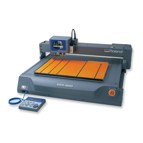
EGX-600/400
4-1 Special Tools ............................................................................. 68
4-2 SERVICE MODE ........................................................................ 69
4-3 HOW TO UPGRADE FIRMWARE ............................................. 72
4-4 X BELT TENSION ADJUSTMENT ............................................. 75
4-5 Y BELTTENSION ADJUSTMENT .............................................. 77
4-6 RIGHT ANGLED ADJUSTMENT OF X RAIL ............................. 79
4-7 CALIBRATION ............................................................................ 80
4-8 X AXIS LOAD CHECK ................................................................ 83
4-9 Y AXIS LOAD CHECK ................................................................ 84
4-10 Z AXIS LOAD CHECK ............................................................... 85
5-1 OPERATIONAL SEQUENCE ..................................................... 86
5-2 SENSOR MAP ............................................................................ 88
6-1 POOR ENGRAVING RESULT ................................................... 89
6-2 NOISE ........................................................................................ 91
6-3 SPINDLE LOCK .......................................................................... 92
6-4 MOTOR ERROR (X, Y, Z Axis) .................................................. 93
7-1 INSTALLATION CHECK LIST .................................................... 94
7-2 MAINTENANCE CHECK LIST .................................................... 98
7-3 Specification ............................................................................... 99
Copyright © 2002 ROLAND DG CORPORATION
1
Structure & Spare Parts
2
Electrical Section
3
Replacement of Main Parts
4
Adjustment
5
Supplemental Information
6
Troubleshooting
7
Service Activities
Second Edition
EGX-600/400 '02. Jul.
5893-01
Advertisement
Table of Contents

Related Manuals for Roland EGX-600


Summary of Contents for Roland EGX-600
-
Page 1: Table Of Contents
Windows and MS-DOS are registered trademark or trademark of Microsoft Corporation in the United States and/or other countries. Second Edition EGX-600/400 ‘02. Jul. Unauthorized copying or transferral, in whole or in part, of this manual is prohibited. Copyright © 2002 ROLAND DG CORPORATION 5893-01... - Page 2 Revision Record Revision Date Description of Changes Approval Issued by First Edition Inagaki Tamaki 2002.5.28 Sect1. [Structure & Parts List] has been added. Inagaki Tamaki 2002.7.11...
- Page 3 To Ensure Safe Work To Ensure Safe Work About Notices. Used for instructions intended to alert the operator to the risk of death or severe injury should the unit be used improperly. Used for instructions intended to alert the operator to the risk of injury or material damage should the unit be used improperly.
-
Page 4: Structure & Spare Parts
BOLT,T-SLOT EGX-600 8 13439801 CABLE-AC 3P CHINA 10A/250V S 9 13509781 CABLE-ASSY HCL-T5-1MP-BL 1M 10 12569515 HEXAGONAL WRENCH 11 21655242 HOLDER,COLLET 4.36 EGX-600 12 26015374 MANUAL,USE EN EGX-600 13 26015373 MANUAL,USE JP EGX-600 14 21575104 NUT,KNURLED RETAINER PNC-2300 15 22055278... -
Page 5: Frame & Controller
1 Structure & Spare Parts 1-2 FRAME & CONTROLLER... - Page 6 22025655 COVER,Y-BASE R EGX-600(5/5) 19 12239406 CUSHION,TM-96-6 7589418000 EGX-400 FRAME-ASSY 7589318000 EGX-600 FRAME-ASSY 21 W589356020 EGX-600 JOG BOARD ASS'Y 22 22475110 KNOB,L MCG MDX-500 23 22535349 LABEL,CARD SLOT EGX-600 #LA425 24 22535352 LABEL,EMERGENCY EGX-600 #LA428 25 22535348 LABEL,INTERFACE EGX-600 #LA424...
-
Page 7: Axis
1 Structure & Spare Parts 1-3 X AXIS... - Page 8 12 22025448 COVER,SIDE L EGX-600 S12 31199703 SCREW,SET WP M3*6 BC 22025657 COVER,SIDE R EGX-400 (2/5) S13 31049136 SCRWE,CAP M4*20 BC 22025652 COVER,SIDE R EGX-600 (2/5) S14 31249225 WASHER,3*12*1 BC 22025639 COVER,TOP EGX-400 22025637 COVER,TOP EGX-600 22025640 COVER,X-FRONT EGX-400 22025638...
-
Page 9: Y Axis
1 Structure & Spare Parts 1-4 Y AXIS... - Page 10 S21 31049136 SCRWE,CAP M4*20 BC 16 W589356050 EGX-600 IF BOARD ASS'Y 17 W589356080 EGX-600 MMC BOARD ASS'Y 18 W589356060 EGX-600 TRANS BOARD 1 ASS'Y 19 7589350000 EGX-600 MAIN BOARD ASS'Y 20 7589353000 EGX-600 SPINDLE BOARD ASS'Y 21 12399313 FILTER(E) TR-20-10-10...
-
Page 11: Z Axis
1 Structure & Spare Parts 1-5 Z AXIS... - Page 12 COVER,Z-CABLE EGX-600 S17 31199710 SCREW,SET WP M3*3 BC 17 12239406 CUSHION,TM-96-6 S18 31199703 SCREW,SET WP M3*6 BC 18 W589356040 EGX-600 BRAKE BOARD 2 ASS'Y S19 31199711 SCREW,SET WP M4*8 BC 19 7589320000 EGX-600 PULLEY M PP S20 31049136 SCRWE,CAP M4*20 BC...
-
Page 13: Electrical Section
2 Electrical Section 2 Electrical Section 2-1 WIRING MAP CN1 1 CN1 0 CN1 6 CN2 1 CN1 1 CN1 1... -
Page 14: Main Board Ass'y
2 Electrical Section 2-2 MAIN BOARD ASS'Y Main Board_Arrangement Diagram / component side Indicates revision of the circuit board. - Page 15 2 Electrical Section Main Board_Component Diagram / component side...
- Page 16 2 Electrical Section Main Board_Arrangement Diagram / soldering side...
- Page 17 2 Electrical Section Main Board_Component Diagram / soldering side...
- Page 18 2 Electrical Section Main Board_1/4 Circuit Diagram...
- Page 19 2 Electrical Section Main Board_2/4 Circuit Diagram...
- Page 20 2 Electrical Section Main Board_3/4 Circuit Diagram...
- Page 21 2 Electrical Section Main Board_4/4 Circuit Diagram...
-
Page 22: Panel Board Ass'y
2 Electrical Section 2-3 SPINDLE BOARD ASS'Y Spindle Board_Arrangement Diagram / component side... - Page 23 2 Electrical Section Spindle Board_Component Diagram / component side...
- Page 24 2 Electrical Section Spindle Board_Arrangement Diagram / soldering side...
- Page 25 2 Electrical Section Spindle Board_Component Diagram / soldering side...
- Page 26 2 Electrical Section Spindle Board_1/3 Circuit Diagram BUPWM BVPWM /BUPWM /BVPWM BUCRNT BVCRNT BWCRNT INT4K 250K HolePulse BWPWM /BWPWM...
- Page 27 2 Electrical Section Spindle Board_2/3 Circuit Diagram...
- Page 28 2 Electrical Section Spindle Board_3/3 Circuit Diagram BBOOT...
-
Page 29: Other Circuit Boars
2 Electrical Section 2-4 OTHER CIRCUIT BOARD Other Circuit Board_Arrangement Diagram / component side... - Page 30 2 Electrical Section Other Circuit Board_Component Diagram / component side...
- Page 31 2 Electrical Section Other Circuit Board_Arrangement Diagram / soldering side...
- Page 32 2 Electrical Section Other Circuit Board_Component Diagram / soldering side...
- Page 33 2 Electrical Section Other Circuit Board_1/4 Circuit Diagram...
- Page 34 2 Electrical Section Other Circuit Board_2/4 Circuit Diagram...
- Page 35 2 Electrical Section Other Circuit Board_3/4 Circuit Diagram...
- Page 36 2 Electrical Section Other Circuit Board_4/4 Circuit Diagram...
-
Page 37: Replacement Of Main Parts
3 Replacement of Main Parts 3 Replacement of Main Parts Following table describes the necessary adjustment after the replacement of each parts. Replacement Parts Necessary Adjustment X MOTOR 1. X Axis Load Check Y MOTOR 1. Y Axis Load Check Z MOTOR 1. - Page 38 3 Replacement of Main Parts Loosen the screws fixing the Flange and remove the Spindle Spindle Belt Belt. There is the collar on the lower right side of the flange. Be careful not to lose it. Screw with collor Screws Remove the Spring and the Screws, and then remove Spring Spindle Motor with the Flange.
- Page 39 3 Replacement of Main Parts Fix the Spindle Motor Pulley to the Spindle Motor with the <Side View of the Spinlde Motor Pulley> Set Screw. Top Part Motor Shaft Spindle Motor Pulley When fixing the Spindle Motor Pulley, it is <Top View of the Spinlde Motor Pulley>...
-
Page 40: Axis Motor_Replacement
3 Replacement of Main Parts 3-2 X Axis Motor_Replacement (Referential Time : 20 minutes) Remove the X Axis Rail Cover, Rail Cover and Right X Axis Rail Cover Side Cover. Right Side Cover Rail Cover Move the Head Carriage to the left end. XY Junction Board Remove the X Motor Cable from the XY Junction Board. - Page 41 3 Replacement of Main Parts Loosen the Set Screws and remove the X Motor Pulley from X Motor the X Motor. Then, remove the X Motor from the Flange and change it to the new one. X Motor Pulley Flange Set Screws <Bottom View>...
- Page 42 3 Replacement of Main Parts Put through the X Motor Pulley to the Drive Belt. Drive Belt Flange Then, tighten up the Screws with the collar and the other Screws temporarily to the Motor Flange. Screws Screws with the collar Attach the Spring and tighten up the screws.
- Page 43 3 Replacement of Main Parts Select the [AXIS X] in the [LOAD] menu and press [ENTER] AXIS X Y Z S key. Then, Carriage moves to the Limit Position. Enter the value 500 and press the [ENTER] key. [ENTER] key AXIS X Y Z S VALUE 500...
-
Page 44: Y Axis Motor_Replacement
3 Replacement of Main Parts 3-3 Y Axis Motor _Repalcement (Referential Time : 20 minutes) Remove the Front Cover. Front Cover Disconnect the Y Motor Cable. Y Motor Cable Remove the Spring and the screws fixing the Flange. Then, remove the Y Motor together with the Flange from the Drive Belt. - Page 45 3 Replacement of Main Parts Loosen the Set Screw and remove Y Motor Pulley from the Y Y Motor Motor. Remove the Y Motor from the Flange and change it to the new one. Set Screws Flange Y Motor Pulley <Front View>...
- Page 46 3 Replacement of Main Parts Put through the Y Motor Pulley to the Drive Belt and tighten the Flange with the Motor temporarily. Drive Belt Attach the Spring and tighten up the screws. Then, connect the Y Motor Cable. Spring <Y Axis Load Check>...
- Page 47 3 Replacement of Main Parts After setting the value, the load check starts. The Carriage moves in the Y direction to check the load.
-
Page 48: Z Axis Motor_ Replacement
3 Replacement of Main Parts 3-4 Z Axis Motor_Replacement (Referential Time : 30 minutes) Remove the Spindle Cover. Spindle Cover Remove the Junction Board Cover. Disconnect the Z Motor Cable, Z Limit Cable and Spindle Motor Cable from the XZ Junction Board. Spindle Motor Cable... - Page 49 3 Replacement of Main Parts Remove the 4 screws fixing the Carriage Unit. And loosen the 2 Set Screws on the Boss Part of the Z Screw. Then, Loosen the 2 Screws on the Z Screw Support. Boss Part of the Z Screw Screws Detach the Carriage Unit from the Carriage Base.
- Page 50 3 Replacement of Main Parts Tighten up the Set Screw on the Boss part of the Z Screw. <Top View> D-Cut Part Set Screw It is necessary to fix the Set Screw against the D-Cut part of the Z Motor Shaft. Boss Part of the At the same time, please be careful if the top of Z Screw...
- Page 51 3 Replacement of Main Parts Tighten up the screws fixing the Carriage Unit. Screws Carriage Unit Connect the INSULOCK TIEs and the Sponge as the figure. Spindle Cable Bush Tighten up the Spindle Motor Cable Bush. Sponge and INSULOCK TIE Be careful with the position of the Sponge.
- Page 52 3 Replacement of Main Parts Select the [AXIS Z] in the [LOAD] menu and press [ENTER] AXIS X Y Z S key. Then, Carriage moves to the Limit Position. Enter the value 350 and press the [ENTER] key. [ENTER] key AXIS X Y Z S VALUE 350...
-
Page 53: Axis Lm Guide_Replacement
3 Replacement of Main Parts 3-5 X Axis LM Guide_Repalcement (Referential Time : 35 minutes) NOTES 1. LM GUIDE has the direction for fixing. Bottom side of the LM GUIDE has the line that indicates its direction and the side plane of the bottom part will be the standard plane. Push the standard plane of the LM GUIDE against the standard plane of the machine when fixing the LM GUIDE. - Page 54 3 Replacement of Main Parts Disconnect the Z Limit Cable, Z Motor Cable and Spindle Motor Cable from the XZ Junction Board. Remove the Screws fixing the Carriage Unit and detach it from the Main Unit. Screws Carrige Unit Remove the Carriage Base from the LM Block. Remove the LM Guide and change it to the new one.
- Page 55 3 Replacement of Main Parts When fixing the X LM Guide, be careful with the <Right> direction. LM Guide Fix the X LM Guide fitting the standard plane with Standard the Pins as the figure. Plane LM Guide <Left> Standard Plane Tighten the screws fixing the LM Guide temporarily.
- Page 56 3 Replacement of Main Parts Connect the Z Motor Cable, Z Limit Cable and Spindle Motor Cable to the XZ Junction Board. Then, fix the Limit Switch and Junction Board Cover. <X Axis Load Check> Turn on the Power while pressing the [ ], [ ], [ keys to enter the Service Mode.
-
Page 57: Y Axis Lm Guide_Replacement
3 Replacement of Main Parts 3-6 Y Axis LM Guide_Repalcement (Referential Time : 35 minutes) NOTES 1. LM GUIDE has the direction for fixing. Bottom side of the LM GUIDE has the line that indicates its direction and the side plane of the bottom part will be the standard plane. Push the standard plane of the LM GUIDE against the standard plane of the machine when fixing the LM GUIDE. - Page 58 3 Replacement of Main Parts Remove the screws fixing the LM Guide. LM Guide Remove the screws fixing the LM Block on the Carriage Rail Carriage and loosen the Set Screws. Rail Screws LM Block Hold the Carriage Rail up and take the LM Guide off. Then, fix the new LM Guide by tightening screws temporarily.
- Page 59 3 Replacement of Main Parts <Rear Side> When fixing the Y LM Guide, be careful with the position of the Screws as the figure. <Front Side> Fix the Carriage Rail to the LM Block and tighten up the Set Screws and Screws. Screws Y LM LM Block...
- Page 60 3 Replacement of Main Parts Tighten up the Screws for fixing the Plate and connect the Flexible Cables Flexible Cables. Then, close the Clamp. Fix the Right Side Cover. Clamp Plate Right Side Cover Screws <Right Angle Adjustment of X Axis> Loosen the Set Screws of the Y Drive Pulley.
- Page 61 3 Replacement of Main Parts <Y Axis Load Check> Turn on the Power while pressing the [ ], [ ], [ keys too enter the Service Mode. [ ], [ ], [ ] + POWER ON Select the [LOAD] menu by pressing the [MENU] key and press [ENTER] key.
-
Page 62: Belt_Replacement
3 Replacement of Main Parts 3-7 X Belt_Repalcement (Referential Time : 30minutes) Remove the X Axis Rail Cover, Rail Cover and Right X Axis Rail Cover Side Cover. Right Side Cover Spindle Cover Rail Cover Move the Carriage to the Right side by hands. Carriage Remove the Junction Board Cover. - Page 63 3 Replacement of Main Parts Loosen the Screw1 and remove the Screw2 and then loosen the Nut2. Nut1 Screw2 Frame Nut2 Screw1 Move the Z Slider to the bottom part by rotating the Z Screws. Z Screw Loosen the screws from the Belt Holder and after that, X Belt remove the X Belt.
- Page 64 3 Replacement of Main Parts X Belt When fixing the X Belt, be careful not to overlap the both end of the Belts. Belt Holder Tighten up the Screws as the figure for fixing the Junction Screws Board Base. Be careful the Limit SW. It is possible to break it when you put the Junction Board Base.
- Page 65 Confirm that the Pressing Force matches with the Bending Amount in reference to the next table. X Belt <Reference Table> Pressing Force Bending Amount EGX-600 720gf 10.0mm EGX-400 720gf 7.0mm When the Pressing Force matches with the Bending Amount, tighten up the Screw1 and Screw2.
- Page 66 3 Replacement of Main Parts Select the [AXIS X] in the [LOAD] menu and press [ENTER] AXIS X Y Z S key. Then, Carriage moves to the Limit Position. Enter the value 500 and press the [ENTER] key. [ENTER] key AXIS X Y Z S VALUE 500...
-
Page 67: Y Belt_Replacement
3 Replacement of Main Parts 3-8 Y Belt_Repalcement (Referential Time : 30 minutes) Remove the Y Rail Cover and the Front Cover. Y Rail Cover Front Cover Loosen the Screw1 and remove Screw2 and then loosen the Nut2. Frame Then, remove the Belt from the Idle Pulley. Belt Screw1 Nut1... - Page 68 Y-Drive Pulley and check the ST-001 bending amount with the ruler. Confirm that the Pressing Force matches with the Bending Amount in reference to the next table. Y Belt <Reference Table> Pressing Force Bending Amount EGX-600 720gf 8.0mm EGX-400 720gf 6.0mm...
- Page 69 3 Replacement of Main Parts When the Pressing Force matches with the Bending Amount, tighten up the Screw1 and Screw2. Then, carry out the X Axis Load check. Frame If the Pressing Force does not match with the Bending Amount, adjust the Belt Tension by Nut1 and 2 again. After that, measure the tension and when the Belt Tension becomes to the proper value, tighten up the Nut1 and 2.
- Page 70 3 Replacement of Main Parts <Y Axis Load Check> Turn on the Power while pressing the [ ], [ ], [ keys to enter the Service Mode. [ ], [ ], [ ] + POWER ON Select the [LOAD] menu by pressing the [MENU] key and press [ENTER] key.
-
Page 71: Adjustment 4-1 Special Tools
4 Adjustment 4 Adjustment 4-1 Special Tool Table shown below is a list of special tools recommended by Roland DG Corporation. Tool No. ST-001 Tool Name TENSION GAUGE 2000g (2N) Purpose Belt Tension Adjustment... -
Page 72: Service Mode
4 Adjustment 4-2 Service Mode... - Page 73 4 Adjustment...
- Page 74 4 Adjustment...
-
Page 75: How To Upgrade Firmware
4 Adjustment 4-3 HOW TO UPGRADE FIRMWARE (Referential Time : 5 minutes) Connect PC and EGX-600/400 with the PARALLEL CABLE. It is necessary to prepare the followings to upgrade the FIRMWARE. 1. FIRMWARE DISK 2. PC with MS-DOS 3. PARALLEL CABLE... - Page 76 4 Adjustment Booter is included in the Firmware. When the Booter version in the Firmware is upgraded to the new one, carry out the following operation. In order to enter the Service Mode, turn on the power while pressing [ ], [ ] and [ ] keys.
- Page 77 4 Adjustment When the program update is finished, "Finished" is Booter Update appeared. Then turn off the Main power Switch. *Now Prosessing Confirm the current Booter version by turning on the power while pressing the [ ] key. Booter update Finished Ver 1.20 BOOT Ver 1.20...
-
Page 78: Belt Tension Adjustment
X-Drive Pulley and check the ST-001 bending amount with the ruler. Confirm that the Pressing Force matches with the Bending Amount in reference to the next table. X Belt <Reference Table> Pressing Force Bending Amount EGX-600 720gf 10.0mm EGX-400 720gf 7.0mm... - Page 79 4 Adjustment When the Pressing Force matches with the Bending Amount, tighten up the Screw1 and 2. If the Pressing Force does not match with the Bending Amount, adjust the Belt Tension by Nut1 and 2 again. After that, measure the tension and when the Belt Tension becomes to the proper value, tighten up the Nut1 and 2.
-
Page 80: Y Belttension Adjustment
Y-Drive Pulley and check the ST-001 bending amount with the ruler. Confir that the Pressing Force matches with the Bending Amount in reference to the next table. Y Belt <Reference Table> Pressing Force Bending Amount EGX-600 720gf 8.0mm EGX-400 720gf 6.0mm... - Page 81 4 Adjustment When the Pressing Force matches with the Bending Amount, tighten up the Screw1 and 2. If the Pressing Force does not match with the Bending Frame Amount, adjust the Belt Tension by Nut1 and 2 again. After that, measure the tension and when the Belt Tension becomes to the proper value, tighten up the Nut1 and 2.
-
Page 82: Right Angled Adjustment Of X Rail
4 Adjustment 4-6 RIGHT ANGLED ADJUSTMENT OF X-RAIL (Referential Time : 5min.) Remove the Front Cover. Front Cover Loosen the Set Screws of the Y Drive Pulley. Y Drive Pulley Set Screws Move the X-Rail to the Rear side frame. Tighten the Set Screws by pushing the X Rail to rear side Y Drive Pulley frame. -
Page 83: Calibration
HOME POSITION : Left Lower Corner : Surface of the material 8000rpm Spindle RPM : 8,000 rpm 5000rpm 15000rpm Turn on the power while pressing [ ] key to enter the [Calibration Mode]. EGX-600/400 engraves as the figure. 190mm 230mm... - Page 84 4 Adjustment Measure the both X-axis and Y-axis Length. Calculate the calibrating amount by the formula shown at < X-axis Calibration> the right. 0.8333 X 230 = Calibrating Amount Measured Length < Example> When Measured Length is 229.5mm. 0.8333 X 230 = 0.83512 229.5 <...
- Page 85 <8355> Attach the ACRYLIC PLATE to the machine and turn on the power while pressing [ ] key to enter the [Calibration Mode] so that the EGX-600/400 engraves. And then, check the length. If NG, repeat 6 to 8 .
-
Page 86: Axis Load Check
4 Adjustment 4-8 X Axis Load Check (Referential Time : 8 minutes) Turn on the Power while pressing the [ ], [ ], [ [ ], [ ], [ ] + POWER ON keys to enter the Service Mode. Select the [LOAD] menu by pressing the [MENU] key and press [ENTER] key. -
Page 87: Y Axis Load Check
4 Adjustment 4-9 Y Axis Load Check (Referential Time : 8 minutes) Turn on the Power while pressing the [ ], [ ], [ keys to enter the Service Mode. [ ], [ ], [ ] + POWER ON Select the [LOAD] menu by pressing the [MENU] key and press [ENTER] key. -
Page 88: Z Axis Load Check
4 Adjustment 4-10 Z Axis Load Check (Referential Time : 8 minutes) Turn on the Power while pressing the [ ], [ ], [ keys to enter the Service Mode. [ ], [ ], [ ] + POWER ON Select the [LOAD] menu by pressing the [MENU] key and press [ENTER] key. -
Page 89: Supplemental Information
5 Supplemental Information 5 Supplemental Information 5-1 OPERATIONAL SEQUENCE... - Page 90 5 Supplemental Information ERROR MESSAGE LIST...
-
Page 91: Sensor Map
5 Supplemental Information 5-2 SENSOR MAP Y LIMIT SENSOR This switch detects the limit in Y direction. Z LIMIT SENSOR X LIMIT SENSOR This switch detects the limit This switch detects the limit in Z direction. in X direction. SPINDLE COVER SWITCH This switch detects whether the Spindle Cover is opened or closed. -
Page 92: Troubleshooting
6 Troubleshooting 6 Troubleshooting 6-1 POOR ENGRAVING RESULT (Shifting / Wavy line / Unstable depth) Poor Engraving Result Flowchart... - Page 93 6 Troubleshooting Poor Engraving Result_Outline...
-
Page 94: Noise
6 Troubleshooting 6-2 NOISE Noise_Flowchart Noise_Outline... -
Page 95: Spindle Lock
6 Troubleshooting 6-3 SPINDLE LOCK Spindle Lock_Flowchart Spindle Lock_Outline... -
Page 96: Motor Error (X, Y, Z Axis)
6 Troubleshooting 6-4 MOTOR ERROR (X, Y, Z AXIS) Motor Error (X, Y, Z axis)_Flowchart Motor Error (X, Y, Z axis)_Outline... -
Page 97: Service Activities
7 Service Activities 7 Service Activities 7-1 INSTALLATION CHECK LIST EGX-600/400 INSTALLATION CHECK LIST User Name Model Serial No. Date EGX-600/400 Minimum Space Required EGX-600 EGX-400 995mm(W) X 820mm(L) X 521mm(H) 795mm(W) X 719mm(L) X 521mm(H) Classification Purcahse Loan Unit... - Page 98 (17 mm : 1, 10 mm : 1) mm) : 1 (3 mm) : 1 Roland Software Package User's Manual : 1 CD-ROM : 1 *1 This is for diameter 4.36 mm character cutters and flat cutters. It cannot be used with diamond scrapers or end mills.
- Page 99 7 Service Activities 2. Remove the four nuts and the retainer shown in the figure. 3. Loosen the three screws shown in the figure and remove the guide temporarily 4. Slide the bolts left on the table in step 2 to detach them. 5.
- Page 100 7 Service Activities EGX-600/400 Emergency Stop to Ensure Safety User The machine immediately stops operating and quits engraving by pressing the Explanation emergency stop switch. Operation Switching the Power On and Off Moving the Spindle Head The speed of movement is determined by how you press the movement buttons.
-
Page 101: Maintenance Check List
7 Service Activities 7-2 MAINTENANCE CHECK LIST EGX-600/400 MAINTENANCE CHECK LIST Date Model Serial No. EGX-600/400 MECHANICAL PARTS Check Points Confirmation X axis 1. Drive Pulley Crack/Dirt 2. Belt Tension 3. Backlash Looseness Y axis 1. Drive Pulley Crack/Dirt 2. Belt Tension 3. -
Page 102: Specification
Operation panel: 1, Operation-panel connector cable: 1, Power cord: 1, Depth regulator nose unit: 1, Solid collet : 1, Clamps : 4, Wrench (17 mm: 1, 10 mm: 1), Hexagonal screw driver (2 mm): 1, Hexagonal wrench (3 mm): 1, Roland Software Package CD-ROM : 1, User's Manual: 1... - Page 103 7 Service Activities Interface Specifications Parallel Connector In compliance with the specification of Centronics Standard STROBE (1BIT), DATA (8BIT) Input signal BUSY (1BIT), ACK (1BIT) Output signal TTL level I/O signal level Asynchronous Transmission method Serial Connector RS-232C specification Standard Asynchronous, duplex data transmission Transmission method 4800, 9600, 19200, 38400...
- Page 104 EGX-600/400...
Need help?
Do you have a question about the EGX-600 and is the answer not in the manual?
Questions and answers