Table of Contents
Advertisement
Quick Links
Advertisement
Table of Contents

Related Manuals for Bosch ABS M4 Kit


Summary of Contents for Bosch ABS M4 Kit
- Page 1 ABS M4 Kit Manual 2.1 6/6/2016...
-
Page 2: Table Of Contents
5.3 ABS M4 Kit Clubsport .................................. 14 5.4 Connector Overview Kit 1 ................................15 5.5 Connector Overview Kit 2 ................................16 5.6 Connector Overview ABS M4 Kit Clubsport ........................16 6 Optional Accessories ............................17 6.1 Hardware ......................................17 6.2 Options for vehicle design ................................. 18 7 Assembling the Parts ............................ - Page 3 17 Wiring Diagram ABS Porsche ........................... 53 18 Wiring Diagram ABS M4 Porsche 991 Cup ..................... 54 19 Wiring Diagram ABS M4 Porsche Clubsport ....................55 20 Wiring Harness ..............................56 21 Wiring Harness Clubsport ..........................57 Bosch Motorsport ABS M4 Manual 3 / 60...
-
Page 4: System Overview
1 | System Overview System Overview 4 / 60 ABS M4 Manual Bosch Motorsport... -
Page 5: Before Use
Safety Information The Bosch Motorsport ABS M4 Kit was developed for use by professionals and requires in depth knowledge of automobile technology and experience in motor‐ sport. Using the system does not come without its risks. -
Page 6: Principle Of Operation
1 for the most sensitive controller setting (e.g. heavy rain condition). The response characteristic gets more progressive from position to position. Finally with switch position 9 the most progressive effect is ach‐ 6 / 60 ABS M4 Manual Bosch Motorsport... - Page 7 You can switch off the ABS functions by switching to position 12. This can be very helpful, e.g. for calibration of the brake balance adjuster. All ABS sensor signals will still be communicated. Every older ABS M4 Kit can be updated to this function.? During warm‐up we recommend to choose position 12. From software status V1017 (available from autumn 2015) on no error entry takes place any longer.
- Page 8 ▪ Reset the System with a switch in the cockpit You can reset the system by moving the switch to the position OFF and then directly again ON. See also 2 Repair Bleeding Wizzard 8 / 60 ABS M4 Manual Bosch Motorsport...
-
Page 9: Technical Data
9 adjustment settings applicable for OEMSs (Pos. 1‐9) 2 adjustment settings applicable for Temas (Pos. 10 and 11) ABS function can be deactivated (Pos. 12) Brake light switch Outputs ABS warning light (MIL) Communication CAN interface Bosch Motorsport ABS M4 Manual 9 / 60... - Page 10 ABS M4‐Package 2 (incl. wiring harness F02U V00 290‐01 with motorsport connectors, individual layout depending on customer require‐ ments, wheel speed sensors with mo‐ torsport connectors) 10 / 60 ABS M4 Manual Bosch Motorsport...
- Page 11 F 02U V01 289‐49 (DF11S) wheel speed sensors with serial con‐ F 02U V00 543‐13 (for DF11i) nectors) 500 kBaud: F 02U V01 289‐48 (DF11S) F 02U V00 543‐12 (for DF11i) Bosch Motorsport ABS M4 Manual 11 / 60...
-
Page 12: Adaptations To Your Vehicle
Was or is the vehicle already fitted with an ABS system? Was or is it an old BOSCH ABS system? The ABS M4 requires signals from differential dual Hallsensors such as the Bosch DF11 or similar to function correctly. These sensor types are used in new vehicles for ABS and ESP®... - Page 13 Adaptations to Your Vehicle | 4 diagram in chapter wheel speed signal splitter 17]. This module can be used, for traction control, display and gear units. For ordering information see also wheel speed signal splitter. Bosch Motorsport ABS M4 Manual 13 / 60...
-
Page 14: Included In The Kit
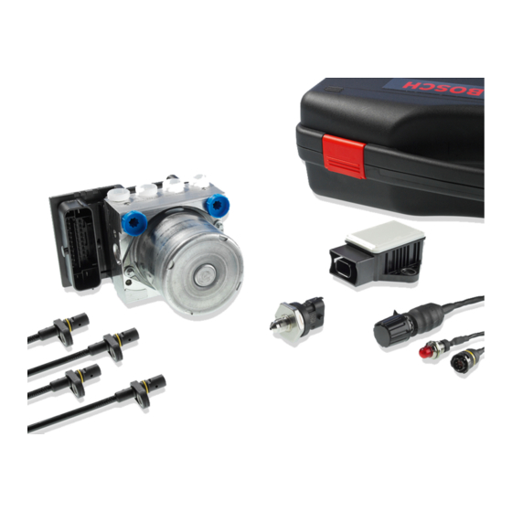
ABS M4 type connectors. ABS M4 Kit 2 ABS M4 Kit 2 with part number F 02U V00 290‐01 includes all the parts from Kit 1, with the exception of a different wiring harness: Description Part Number Similar to Kit 1, but wheel speed sen‐... -
Page 15: Connector Overview Kit 1
ABS M4 Clubsport 55]. Connector Overview Kit 1 ABS M4 Kit 1 with part number F 02U V00 289‐01 includes the following connec‐ tors, which are also available as individual spare parts: Connector for Part Number... -
Page 16: Connector Overview Kit 2
F 02U B00 435‐01 Connector Overview Kit 2 ABS M4 Kit 2 with part number F 02U V00 290‐01 includes a harness with all the connectors from Kit 1, with the exception of a different connector for the wheel speed sensors:... -
Page 17: Optional Accessories
These sensors are used in current ABS and ESP® systems. The four speed sensors included in the ABS M4 Kit meet this classification. The signal of a regular speed sensor, as found in older series production ABS applications, is not com‐... -
Page 18: Options For Vehicle Design
All ABS M4 data can be stored on a CAN‐compatible data logger. We recom‐ mend to use our C 50/C 60 data logger for storing ABS M4 data. Bosch Motorsport provides a standardized CAN log in DBC format for analyzing recorded CAN data, see chapter ABS_M4.dbc. -
Page 19: Assembling The Parts
Secure the hy‐ draulic power unit to the assembly plate supplied with the ABS M4 Kit using the three M6x1 screw threads on the underside of the casing. To reduce vibration, rubber pads should be fitted between the assembly plate and the vehicle chassis. -
Page 20: Brake Pressure Sensor
48]. Wheel Speed Sensors Bosch Motorsport ABS M4 needs special edited wheel speed signals, which are supplied only from active speed sensors like e.g. from Bosch DF11‐family. These double hall sensors operate on the differential principle. The ABS M4 needs all... -
Page 21: Encoder Wheel
Encoder wheels usually have 48 teeth. The tooth/gap ratio should be approx. 50 % and the teeth should be approx. 3 mm in height. The encoder wheel must be made of a ferromagnetic material. If required, Bosch Motorsport can provide technical documentation on positioning the encoder wheel. See the back cover of this booklet for our contact information. -
Page 22: Gyro/Acceleration Sensor
Features 6]. The switch position is also broadcast on the CAN Bus so it can be displayed with a dash (e. g. the DDU 7 from Bosch Motorsport). Only use the supplied ABS Map Switch. Notice Don´t exceed the max. -
Page 23: Diagnosis Interface
26], to program settings specific to the vehicle and open/delete error messages. Before using the MSA Box II for the first time you have to install a driver on your laptop, which you can find for free download on our homepage www.bosch‐mo‐ torsport.de. See also ABS M4 – Laptop communication 7.10... -
Page 24: Brake Lines
Use brake calipers that are as rigid as possible. The higher the brake pressure is, the larger is the elasticity of the brake. A blocking pressure of max. 80 bar is optimal. 24 / 60 ABS M4 Manual Bosch Motorsport... -
Page 25: Abs M4 - Laptop Communication
Installing the MSA Box II driver: Before using the MSA Box II for the first time you need to install a specific driver on your laptop. Find the driver for free download on our website www.bosch‐ motorsport.de. Please make sure that the MSA Box II is not connected to the Notice laptop while you are installing the driver. -
Page 26: Programming And Diagnosis Software
After installing the MSA Box II you need to install the programming and diagnos‐ tic software RaceABS 1.1.x. You can find the software including the installation for free download on our website: www.bosch‐motorsport.de. Switch on the ignition Plug the MSA Box's USB connector into your laptop and its motorsport connec‐... -
Page 27: Features Of The Programming And Diagnosis Software
If you don´t see plain text or if there is a red colored warning, you do not have the suitable Fps‐File to your software. Bosch Motorsport ABS M4 Manual 27 / 60... - Page 28 ASR, testing, ECU info) simultaneously, fill in a name and a comment in the given fields and click on the button “Save”. If there are problems, you can send the exported file to your dealer or OEM cus‐ tomer service. 28 / 60 ABS M4 Manual Bosch Motorsport...
- Page 29 Within the windows “Vehicle Data ABS” and “Vehicle Data ASR” a short declara‐ tion or the measuring unit for each value can be shown. By holding the cursor over a data range a small window with the declaration occurs. Bosch Motorsport ABS M4 Manual 29 / 60...
- Page 30 Each ABS‐ECU communicates only with defined sensors. To connect the ABS‐ECU with another sensor you have to fill in the number of the sensor in the field “Yaw‐ Rate/ACC Sensor Part Id”: 30 / 60 ABS M4 Manual Bosch Motorsport...
- Page 31 With the vehicle jacked up, individually spin all four wheels clockwise and check for the proper front/back, left/right allocation. When you spin each wheel the corresponding position should show a value in the RaceABS software under the “Testing” tab: Bosch Motorsport ABS M4 Manual 31 / 60...
- Page 32 Step 5: Testing the electrical pump motor If you click on the "Pump" button, the pump motor should run for 10 seconds or until the same button would be pressed again. 32 / 60 ABS M4 Manual Bosch Motorsport...
- Page 33 Display showing a reaction for each rotary motion? With every clockwise rotation the number of measuring points should increase by 1.ABS warning light (MIL) should shine permanent in switch position 12 (OFF). Bosch Motorsport ABS M4 Manual 33 / 60...
- Page 34 Repair Bleeding Wizzard. During the ABS bleeding process the brake pedal should be ac- tuated continuously except when opening or closing brake bleeder valves. 34 / 60 ABS M4 Manual Bosch Motorsport...
- Page 35 ABS warning light (MIL) does NOT light up when you turn the ignition or ABS M4 on, you must establish the reason for this before taking any further action or before driving the vehicle. Maybe the light bulb is not tightened firmly. Bosch Motorsport ABS M4 Manual 35 / 60...
- Page 36 You can access the log by clicking on “ECU Info” tab in the RaceABS software. The following list shows the most common error log entries and their descrip‐ tion: Multi switch = ABS Map switch Notice 36 / 60 ABS M4 Manual Bosch Motorsport...
- Page 37 “Clear faults” button, as seen below: Then turn ABS M4 off and on again. After the software was deactivated, the indi‐ cation lamp is no longer lit. Bosch Motorsport ABS M4 Manual 37 / 60...
- Page 38 If not all the faults are described in clear text or if there is no Notice error description, please check if you use the correct FPS-file or contact Bosch Motorsport for update(see chapter: --- MISSING LINK ---). Ignition Cycle Counter The ignition cycle counter shows how often the ignition was switched on.
-
Page 39: Appendix
10.1 Startup Checklist This short checklist is intended to supplement the ABS M4 Kit’s manual, not re‐ place it. Prior to using this checklist the user/installer should read the ABS man‐ ual, especially sections Options to 9 to ABS M4 - Laptop Communication 25]. - Page 40 See chapter: ABS in Motorsport and Features ▪ ABS warning light (MIL) on for a short time when you switch on the ignition, on permanent when map switch in position 12 (OFF). 40 / 60 ABS M4 Manual Bosch Motorsport...
-
Page 41: Can Protocol
Brake Light Switch EBD Lamp EBD Fault Lamp ABS Active ABS Active Bit ABS Lamp ABS Fault Lamp AX1_Bremse60 0,00012742 ‐4,1768 ‐4,1768 ‐4,1765 Longitudinal Acceleration (Ax) AY1_Bremse 0,00012742 ‐4,1768 ‐4,1768 ‐4,1765 Lateral Acceleration (Ay) Bosch Motorsport ABS M4 Manual 41 / 60... -
Page 42: Downloads
0x143 0x343 0x5C0 0x24A 0x541 0x70 10.3 Downloads If you visit our website www.bosch‐motorsport.de you will find: ▪ CAD files ▪ Datasheet ▪ Manual ▪ Product information ▪ Form for vehicle‐data ▪ Diagnosis software ▪ ABS_M4.dbc ▪ MSA Box II driver 10.4... - Page 43 Appendix | 10 WENDLAND MOTORENTECHNIK GMBH Im Hitzenried 3 72414 Rangendingen Tel.: +49 7471 871150 Fax: +49 7471 871152 www.wendland‐motorentechnik.de Bosch Engineering GmbH Motorsport Robert‐Bosch‐Allee 1 74232 Abstatt Tel.: +49 7062 911 79101 Fax: +49 7062 911 79104 motorsport@bosch.de www.bosch‐motorsport.de...
- Page 44 10 | Appendix Robert Bosch Ltd Motorsport Control Tower Building, MIRA Technology Park Watling Street Nuneaton Warwickshire CV10 0TU Tel +44 7976 50 4447 motorsport@uk.bosch.com Italy POWERON Via Roma, 23 38030 Castello di Fiemme (TN) Tel: +39 0462 341015 Fax: +39 0462 248383 info@poweron.it...
- Page 45 S & S Diesel Motorsport 6131 Tyler Street Hudsonville, MI 49426 +1 616 915‐8461 www.snsdieselmotorsport.com Robert Bosch LLC Bosch Engineering North America Motorsport 38000 Hills Tech Drive Farmington Hills, MI 48331‐3417 +1 248 876‐2977 www‐bosch‐motorsport.com Latin America Robert Bosch Ltda...
- Page 46 Tsuen Wn, Hong Kong Tel : + 852 3525 0867 Fax : +852 2567 7222 info@soma‐power.com www.soma‐power.com Australia, Newseeland und South Afrika Robert Bosch Pty. Ltd 1555 Centre Road Clayton, Victoria, 3168 Australia Tel. +61 3 9541 3901 Fax +61 3 9541 7225 motor.sport@au.bosch.com...
-
Page 47: Offer Drawing: Hydraulic Power Unit With Attached Control Unit
Offer Drawing: Hydraulic Power Unit with attached Control Unit | 11 Offer Drawing: Hydraulic Power Unit with attached Control Unit Bosch Motorsport ABS M4 Manual 47 / 60... -
Page 48: Offer Drawing: Brake Pressure Sensor
12 | Offer Drawing: Brake Pressure Sensor Offer Drawing: Brake Pressure Sensor 0 261 B08 072 06 48 / 60 ABS M4 Manual Bosch Motorsport... -
Page 49: Mounting Instructions: Brake Pressure Sensor
Mounting Instructions: Brake Pressure Sensor | 13 Mounting Instructions: Brake Pressure Sensor Bosch Gasoline Systems, P81 | 2703373053 DRW 001 03 | SAP-Status 40 | Labor F28 | Change F030GD000901 Ausdrucke und Kopien unterliegen nicht dem Änderungsdienst Ausgedruckt am 13.02.2009 von ole2fe... -
Page 50: Offer Drawing: Wheel Speed Sensor
14 | Offer Drawing: Wheel Speed Sensor Offer Drawing: Wheel Speed Sensor 50 / 60 ABS M4 Manual Bosch Motorsport... -
Page 51: Offer Drawing: Gyro/Acceleration Sensor
Offer Drawing: Gyro/Acceleration Sensor | 15 Offer Drawing: Gyro/Acceleration Sensor Bosch Motorsport ABS M4 Manual 51 / 60... -
Page 52: Wiring Diagram Abs M4
16 | Wiring Diagram ABS M4 Wiring Diagram ABS M4 52 / 60 ABS M4 Manual Bosch Motorsport... -
Page 53: Wiring Diagram Abs Porsche
Wiring Diagram ABS Porsche | 17 Wiring Diagram ABS Porsche Bosch Motorsport ABS M4 Manual 53 / 60... -
Page 54: Wiring Diagram Abs M4 Porsche 991 Cup
18 | Wiring Diagram ABS M4 Porsche 991 Cup Wiring Diagram ABS M4 Porsche 991 Cup 54 / 60 ABS M4 Manual Bosch Motorsport... -
Page 55: Wiring Diagram Abs M4 Porsche Clubsport
Wiring Diagram ABS M4 Porsche Clubsport | 19 Wiring Diagram ABS M4 Porsche Clubsport Bosch Motorsport ABS M4 Manual 55 / 60... -
Page 56: Wiring Harness
MSD-NA BEG/MSD-NA SP//CAN - SB 2008.03.02 Alex Wood MSD-NA BEG/MSD-NA initial drawing 2008.12.03 Bergenske MSD-NA BEG/MSD-NA Kabelabgang Kabelabgang DOWN "DOWN 90" "DOWN" F.02U.V00.xxx-05 F.02U.S00.043-09 ABS M4 Harness -Project Name- ABS M4 F.02U.V00.xxx-05 56 / 60 ABS M4 Manual Bosch Motorsport... -
Page 57: Wiring Harness Clubsport
Wiring Harness Clubsport | 21 Wiring Harness Clubsport Bosch Motorsport ABS M4 Manual 57 / 60... - Page 58 21 | Wiring Harness Clubsport 58 / 60 ABS M4 Manual Bosch Motorsport...
- Page 60 Bosch Engineering GmbH Motorsport Robert-Bosch-Allee 1 74232 Abstatt Germany www.bosch-motorsport.com...
Need help?
Do you have a question about the ABS M4 Kit and is the answer not in the manual?
Questions and answers