Table of Contents
Advertisement
Quick Links
Advertisement
Table of Contents

Related Manuals for Advantech SOM-5883


Summary of Contents for Advantech SOM-5883
- Page 1 User Manual SOM-5883 CPU Computer on Module...
- Page 2 No part of this manual may be reproduced, copied, translated, or transmitted in any form or by any means without the prior written permission of Advantech Co., Ltd. The information provided in this manual is intended to be accurate and reliable.
- Page 3 This product has passed the CE test for environmental specifications when shielded cables are used for external wiring. We recommend the use of shielded cables. This type of cable is available from Advantech. Please contact your local supplier for ordering information.
- Page 4 Discard used batteries according to the manufacturer's instructions.” Note! Notes provide additional, optional information. Document Feedback To assist us with improving this manual, we welcome all comments and constructive criticism. Please send all feedback in writing to support@advantech.com. SOM-5883 User Manual...
- Page 5 45W/ 5883D4R 11155MR 2.4GHz 4.4GHz RM590E ECC Active °C;-40 ~ X-U4A1 E (4C) 185 °F SOM- Xeon W- -40 ~ 85 5883D8R 11865ML 1.5GHz 4.5GHz 25W 24MB RM590E ECC Active °C;-40 ~ X-S5A1 E (8C) 185 °F SOM-5883 User Manual...
- Page 6 Before system installation, check that the items listed below are included and in good condition. If any item does not accord with the list, contact your dealer immediately. Part No. Description Quantity SOM-5883 COM module 1970005238T000 Heatspreader of SOM-5883 Development Board Part No.
- Page 7 In accordance with IEC 704-1:1982 specifications, the sound pressure level at the operator’s position does not exceed 70 dB (A). DISCLAIMER: These instructions are provided according to IEC 704-1 standards. Advantech disclaims all responsibility for the accuracy of any statements contained herein. SOM-5883 User Manual...
- Page 8 SOM-5883 User Manual viii...
-
Page 9: Table Of Contents
1.3.9 I/O ....................7 1.3.10 Power Management..............10 1.3.11 Environment................10 1.3.12 MTBF ..................11 1.3.13 OS Support ................. 11 1.3.14 Advantech iManager ..............11 1.3.15 Power Consumption..............11 1.3.16 Performance ................12 1.3.17 Pin Description................12 Chapter Mechanical Information ....13... - Page 10 Figure 3.45SerialIo Configuration..........65 Security Chipset..................66 Figure 3.46Security Chipset ............66 3.6.1 Secure Boot ................67 Figure 3.47Secure Boot.............. 67 3.6.2 Boot Setup .................. 68 Figure 3.48Boot Setup..............68 Save & Exit ..................... 69 Figure 3.49Save & Exit............... 69 SOM-5883 User Manual...
- Page 11 4.2.1 Windows Driver Setup ..............72 4.2.2 Other OS..................72 Advantech iManager ................73 Appendix A Pin Assignment .........75 SOM-5883 Pin Assignment..............76 Appendix B Watchdog Timer ........83 Programming the Watchdog Timer ............84 Appendix C Programming GPIO ......85 GPIO Register..................86...
- Page 12 SOM-5883 User Manual...
-
Page 13: Chapter 1 General Information
Chapter General Information This chapter details background information on the SOM-5883 CPU Computer on Module. Sections include: Introduction Functional Block Diagram Product Specifications... -
Page 14: Introduction
4 x 4K independent displays via 3 x DisplayPort 1.4/HDMI 2.1, 1 x optional eDP or LVDS, and 1 x VGA interface. SOM-5883 can be configured with up to 2 x 8K HDR outputs. It also supports optional NVMe SSD, TPM 2.0 on-board design, 8.5 ~ 20V power input, and wide operating temperatures (-40 ~ 85 °C;... - Page 15 Serial Presence Detect – refers to serial EEPROM on DRAMs that has DRAM Module configuration information Trusted Platform Module, chip to enhance the security features of a com- puter system UEFI Unified Extensible Firmware Interface Watchdog Timer SOM-5883 User Manual...
-
Page 16: Functional Block Diagram
Functional Block Diagram SOM-5883 User Manual... -
Page 17: Product Specification
Power Good VCC_5V_SBY Contacts Sleep Thermal Protection Lid Input Battery Low Alarm Suspend/Wake Signals Fan PWM/Tachometer Trusted Platform Modules Display Digital Display Interfaces 1 - 3 PEG (PCI Express x16) PCI Express x1 USB 3.0 Rapid Shutdown SOM-5883 User Manual... -
Page 18: Processor System
1.3.4 Memory There are a total of 4 memory sockets on SOM-5883, top side 2pcs by default and bottom side 2pcs optional. This solution supports max 128GB capacity (utilizing ECC memory modules with specific SKU.) with 260pin SO-DIMM sockets (dual-channel). -
Page 19: Lpc
1.3.9.3 USB 3.2/USB 2.0 COM-Express supports USB 3.0 but SOM-5883 supports 4 x USB 3.2 Gen2 (10 Gbps) ports and 8 x USB 2.0 (480 Mbps) ports which are reverse compatible to USB1.x. For USB 3.2, product supports LPM (U0, U1, U2, and U3) for power effi- ciency. - Page 20 Supports 2 x Fan PWM control signals and 2 x tachometer input for fan speed detec- tion. Provides 1 x on module with connector and the other to the carrier board follow- ing PICMG COM Express R3.0 specifications. SOM-5883 User Manual...
- Page 21 SPI_CS0# to Carrier Board, SPI_CS1# to Module SPI_CS0# to Module, SPI_CS1# to Carrier Board Note: If system COMS is cleared, Advantech strongly suggests going to the BIOS setup menu and loading default settings on the first boot up. The standard module has no jumper at SCN6, so BIOS settings are kept without a RTC coin battery.
-
Page 22: Power Management
1.3.10.5 Advantech S5 ECO Mode (Deep Sleep Mode) Advantech iManager provides additional features allowing the system to enter a very low suspended power mode – S5 ECO mode. In this mode, the module will cut all power, including suspended and active power to the chipset, and keep an on-module controller active. -
Page 23: Mtbf
Link: http://com.advantech.com 1.3.13 OS Support The mission of Advantech Embedded Software Services is to "Enhance quality of life with Advantech platforms and Microsoft Windows Embedded technology." We enable Windows Embedded software products on Advantech platforms to more effectively support the embedded computing community. Customers are freed from the hassle of dealing with multiple vendors (hardware suppliers, system integrators, embedded OS distributors) for projects. -
Page 24: Performance
1.3.17 Pin Description Advantech provides useful checklists for schematic design and layout routing. The schematic checklist will specify details about each pin’s electrical properties and how to connect it in different scenarios. The layout checklist will specify the layout con- straints and recommendations for trace length, impedance, and other necessary information during design. -
Page 25: Chapter 2 Mechanical Information
Chapter Mechanical Information This chapter details mechanical information for the SOM-5883 CPU Computer on Module. Sections include: Board Information Mechanical Drawings Assembly Drawings... -
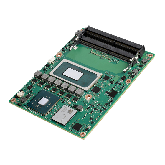
Page 26: Board Information
Board Information The figures below demonstrate the main chips on SOM-5883 Computer-on-Module. Be aware of these positions while designing your customer’s carrier board to avoid mechanical damage and to improve thermal dissipation performance. 11th Genera on Intel® Core™ Processor Smart FAN controller DDR4 SO-DIMM Intel®... -
Page 27: Mechanical Diagram
Mechanical Diagram For more details regarding 2D/3D models, please visit the Advantech COM support service website http://com.advantech.com. Figure 2.3 Board Mechanical Diagram – Front Figure 2.4 Board Mechanical Diagram – Rear Figure 2.5 Board Mechanical Diagram – Side 1 SOM-5883 User Manual... - Page 28 Figure 2.6 Board Mechanical Diagram – Side 2 SOM-5883 User Manual...
-
Page 29: Assembly Diagram
These figures demonstrate the order of assembly needed when attaching the thermal module and COM module to the carrier board. Figure 2.7 Assembly Diagram There are 5 x reserved screw holes for SOM-5883 used to assemble the heat spreader. SOM-5883 User Manual... -
Page 30: Assembly Diagram
Assembly Diagram Consider the CPU and chip height tolerance when designing your thermal solution. Figure 2.8 CPU Height and Tolerance Figure 2.9 PCH Height and Tolerance SOM-5883 User Manual... -
Page 31: Chapter 3 Ami Bios
Chapter AMI BIOS This chapter details BIOS setup information for the SOM-5883 CPU computer-on module. Sections include: Introduction Entering Setup Hot/Operation Key Exit BIOS Setup Utility... -
Page 32: Introduction
This information is stored in flash ROM so it retains the Setup information when the power is turned off. Entering Setup Turn on the computer and then press <DEL> or <ESC> to enter the Setup menu. SOM-5883 User Manual... -
Page 33: Main Setup
System Date using the <Arrow> keys. Enter new values through the keyboard. Press the <Tab> key or the <Arrow> keys to move between fields. The date must be entered in MM/DD/YY format. The time must be entered in HH:MM:SS format. SOM-5883 User Manual... -
Page 34: Advanced Bios Features Setup
Advanced BIOS Features Setup Select the Advanced tab from the SOM-5883 setup screen to enter the Advanced BIOS Setup screen. Users can select any item in the left frame of the screen, such as CPU Configuration, to go to the sub menu for that item. Users can display an Advanced BIOS Setup option by highlighting it using the <Arrow>... -
Page 35: Rc Acpi Settings
Figure 3.4 RC ACPI Settings Low Power S0 Idle Capability This variable determines if we enable ACPI Lower Power S0 Idle Capability (Mutually exclusive with Smart connect). While this is enabled, it also disable 8254 timer for SLP_S0 support. SOM-5883 User Manual... -
Page 36: Cpu Configuration
Number of cores to enable in each processor package. Hyper-Threading Enable or Disable Hyper-Threading Technology. Enable/Disable AES (Advanced Encryption Standard). MonitorMwait Enable/Disable Monitor Mwait. Intel Trusted Execution Technology Enables utilization of additional hardware capabilities provided by Intel (R) Trusted Execution Technology. SOM-5883 User Manual... -
Page 37: Power & Performance
3.4.3 Power & Performance Figure 3.6 Power & Performance CPU - Power Management Control CPU - Power Management Control Options. GT - Power Management Control GT - Power Management Control Options. SOM-5883 User Manual... - Page 38 Enable/Disable processor Turbo Mode (requires EMTTM enabled too). AUTO means enabled. Config TDP Configurations Config TDP Configurations. C states Enable/Disable CPU Power Management. Allows CPU to go to C states when it's not 100% utilized. SOM-5883 User Manual...
- Page 39 Config TDP Configurations Figure 3.8 Config TDP Configurations Configurable TDP Boot Mode Configurable TDP Mode as Nominal/Up/Down/Deactivate TDP selection. Deac- tivate option will set MSR to Nominal and MMIO to Zero. SOM-5883 User Manual...
- Page 40 3.4.3.2 GT - Power Management Control Figure 3.9 GT - Power Management Control RC6 (Render Standby) Check to enable render standby support. SOM-5883 User Manual...
- Page 41 Figure 3.10 PCH-FW Configuration AMT Configuration Configure Intel(R) Active Management Technology Parameters. ME Unconfig on RTC Clear When Disabled ME will nor unconfigured on RTC clear. Firmware Update Configuration Configure Management Engine Technology Parameters. SOM-5883 User Manual...
- Page 42 3.4.4.1 AMT Configuration Figure 3.11 AMT Configuration OEM Flags Settings Configure OEM Flags. SOM-5883 User Manual...
- Page 43 OEMFlag Bit 6: Hide Unconfigure ME confirmation prompt when attempting ME unconfiguration. MEBx OEM Debug Menu Enable OEMFlag Bit 14: Enable OEM debug menu in MEBx. Unconfigure ME OEMFlag Bit 15: Unconfigure ME with resetting MEBx password to default. SOM-5883 User Manual...
- Page 44 3.4.4.2 Firmware Update Configuration Figure 3.13 Firmware Update Configuration Me FW Image Re-Flash Enable/Disable Me FW Image Re-Flash function. SOM-5883 User Manual...
- Page 45 Enable/Disable CPU Power Management. Allows CPU to go to C states when it's not 100% utilized. Intel(R) Speed Shift Technology Enable/Disable Intel(R) Speed Shift Technology support. Enabling will expose the CPPC v2 interface to allow for hardware controlled P-states. SOM-5883 User Manual...
- Page 46 Set to enable low latency of legacy IO. Some systems require lower IO latency irrespective of power. This is a tradeoff between power and IO latency. CPU PCI Express Configuration PCH PCI Express Configuration SOM-5883 User Manual...
- Page 47 TPM 2.0 devices, Auto will support both with the default set to TPM 2.0 devices if not found, TPM 1.2 devices will be enumerated. Disable Block Sid Override to allow SID authentication in TCG Storage device. SOM-5883 User Manual...
- Page 48 OS. ACPI Sleep State Select the highest ACPI sleep state the system will enter when the SUSPEND button is pressed. S3 Video Repost Enable or Disable S3 Video Repost. SOM-5883 User Manual...
- Page 49 Serial Port 2 Configuration Set Parameters of Serial Port 2 (COMB). Hardware Monitor Monitor hardware status. ACPI Report Method Configuration Select ACPI Reporting Method for EC Devices. CAN0 Control Enable/Disable CAN0 controller on RDC-IS200. SOM-5883 User Manual...
- Page 50 I2C0 Control Enable/Disable I2C0 controller on RDC-IS200. SMBus0 Control Enable/Disable SMBus0 controller on RDC-IS200. 3.4.8.1 Hardware Monitor Figure 3.18 Hardware Monitor SOM-5883 User Manual...
- Page 51 3.4.8.2 Serial Port 1 Configuration Figure 3.19 Serial Port 1 Configuration Serial Port Enable or Disable Serial Port (COM). Change Settings Select an optimal settings for Super IO Device. SOM-5883 User Manual...
- Page 52 Otherwise -> Reported vendor _HID. (Driver installation is necessary.) ACPI Report Method for GPIO Select the ACPI reporting method for EC GPIO. PNP0C02 -> Reported as reserved motherboard resource. Otherwise -> Reported vendor _HID. (Driver installation is necessary.) SOM-5883 User Manual...
- Page 53 Console Redirection Enable or Disable. Console Redirection Settings The settings specify how the host computer and the remote computer (which the user is using) will exchange data. Both computers should have the same or compatible settings. SOM-5883 User Manual...
- Page 54 Once the buffers are empty, a 'start' signal can be sent to re-start the flow. Hard- ware flow control uses two wires to send start/stop signals. VT-UTF8 Combo Key Support Enable VT-UTF8 Combination Key Support for ANSI/VT100 terminals. SOM-5883 User Manual...
- Page 55 When Bootloader is selected, then Legacy Console Redirection is disabled before booting to legacy OS. When Always Enable is selected, then Legacy Console Redirection is enabled for legacy OS. Default setting for this option is set to Always Enable. SOM-5883 User Manual...
- Page 56 Stop Bits EMS Stop bits indicate the end of a serial data packet. (A start bit indicates the begin- ning). The standard setting is 1 stop bit. Communication with slow devices may require more than 1 stop bit. SOM-5883 User Manual...
- Page 57 3.4.10 Intel TXT Information Figure 3.25 Intel TXT Information SOM-5883 User Manual...
- Page 58 Maximum time the device will take before it properly reports itself to the Host Controller. 'Auto' uses default value: for a Root port it is 100 ms, for a Hub port the delay is taken from Hub descriptor. GH PicoBoost PMAP SOM-5883 User Manual...
- Page 59 Wait time in seconds to press ESC key to abort the PXE boot. Use either +/- or numeric keys to set the value. Media detect count Number of times presence of media will be checked. Use either +/- or numeric keys to set the value. SOM-5883 User Manual...
- Page 60 3.4.13 NVME Configuration Figure 3.28 NVME Configuration SM681GEC AES (Note: This is optional component.) SOM-5883 User Manual...
- Page 61 Controller and Namespace option will take lot longer to complete the test. Run Device Self Test Perform device self test for the corresponding Option and Action selected by user.Pressing 'Esc' key will abort the test. Result shown below is the recent result logged in the device. SOM-5883 User Manual...
- Page 62 Chipset Setup Figure 3.30 Chipset Setup System Agent (SA)Configuration System Agent Parameters. PCH-I0 Configuration PCH parameters. SOM-5883 User Manual...
- Page 63 Graphic Configuration VMD setup menu VMD Configuration. VT-d VT-d capability. Above 4GB MMIO BIOS assignment Enable/Disable above 4GB memory mapped IO BIOS assignment. This is enabled automatically when aperture size is set to 2048MB. SOM-5883 User Manual...
- Page 64 Maximum value of TOLUD. Dynamic assignment would adjust TOLUD automat- ically based on the largest MMIO length of installed graphic controller. SA GV System Agent Geyserville. Can disable, fix to a specific point, or enable fre- quency switching. SOM-5883 User Manual...
- Page 65 DVMT Pre-Allocated Select DVMT5.0 pre-allocated(fixed) Graphics Memory size is used by the inter- nal graphics device. DVMT Total Gfx Mem Select DVMT5.0 total graphic memory size is used by the internal graphic device. LCD Control SOM-5883 User Manual...
- Page 66 LCD Control Figure 3.34 LCD Control LCD Panel Type Select LCD panel used by Internal Graphics Device by selecting the appropriate setup item. SOM-5883 User Manual...
- Page 67 Enable VMD Global Mapping Enable/Disable to VMD Global Mapping. Map this Root Port under VMD RAID0 Enable/Disable RAID0 feature. RAID1 Enable/Disable RAID1 feature. Intel(R) Optane(TM) Memory Enable/Disable System Acceleration with Intel(R) Optane(TM) Memory feature. SOM-5883 User Manual...
- Page 68 Figure 3.36 PCI Express Configuration PEG PCIe Port Config Config PEG PCIe Lane 0~15 setting. PCI Express Root Port 1 PCI Express Root Port 2 PCI Express Root Port 3 PCI Express Root Port 4 SOM-5883 User Manual...
- Page 69 Slot: this root port connects to user-accessible slot. Slot Implemented bit will be set. ASPM PCI Express Active State Power Management settings. Hot Plug PCI Express Hot Plug Enable/Disable. PCIe Speed Configure PCIe Speed. SOM-5883 User Manual...
- Page 70 Pcie Ref Pll SSC Pcie Ref Pll SSC Percentatge. AUTO - Keep hw default, no BIOS override. Range is 0.0%-0.5%. SPD Write Disable Enable/Disable setting SPD Write Disable. For security recommendations, SPD write disable bit must be set. SOM-5883 User Manual...
- Page 71 PCI Express Root Port 2 PCI Express Root Port 3 PCI Express Root Port 4 PCI Express Root Port 5 PCI Express Root Port 6 PCI Express Root Port 7 SOM-5883 User Manual...
- Page 72 Slot: this root port connects to user-accessible slot. Slot Implemented bit will be set. ASPM PCI Express Active State Power Management settings. Hot plug PCI Express hot plug enable/disable. PCIe Speed Configure PCIe Speed. SOM-5883 User Manual...
- Page 73 SATA Controller Speed Indicates the maximum speed the SATA controller can support. Port 0 Enable or Disable SATA Port. SATA Device Type Identify the SATA port is connected to Solid State Drive or Hard Disk Drive. SOM-5883 User Manual...
- Page 74 Selectively Enable/Disable the corresponding USB port from reporting a Device Connection to the controller. USB SS Physical Connector #0 Enable/Disable this USB Physical Connector (physical port). Once disabled, any USB devices plug into the connector will not be detected by BIOS or OS. SOM-5883 User Manual...
- Page 75 RTC Memory Lock Enable will lock bytes 38h-3Fh in the lower/upper 126 –byte bank of RTC RAM. BIOS Lock Enable/Disable the PCH BIOS lock enable feature. Required to be enabled to ensure SMM protection of flash. SOM-5883 User Manual...
- Page 76 3.5.2.5 HD Audio Subsystem Configuration Settings Figure 3.44 HD Audio Subsystem Configuration Settings HD Audio Control Detection of the HD-Audio device. Disabled=HDA will be unconditionally disabled. Enabled=HDA will be unconditionally enabled. SOM-5883 User Manual...
- Page 77 I2C0 and I2C1,2,3 UART0 and UART1,SPI0,1 UART2 and I2C4,5 UART 0 (00:30:00) cannot be disabled when: 1. Child device is enabled like CNVi Bluetooth (\_SB.PC00.UA00.BTH0) UART 0 (00:30:00) cannot be enabled when: 1. I2S Audio codec is enabled (\_SB.PC00.I2C0.HDAC) SOM-5883 User Manual...
- Page 78 Security Chipset Figure 3.46 Security Chipset Administrator Password Set Setup Administrator Password. User Password Set User Password. Secure Boot Secure Boot Configuration. SOM-5883 User Manual...
- Page 79 System is in User mode. The mode change requires platform reset. Secure Boot Mode Secure Boot mode options: Standard or Custom. In Custom mode, Secure Boot Policy variables can be configured by a physi- cally present user without full authentication. SOM-5883 User Manual...
- Page 80 Select the keyboard NumLock state. Quiet Boot Enables or disables Quiet Boot option. Boot Option #1 Sets the system boot order. Fast Boot Enable or Disable FastBoot features. Most probes are skipped to reduce time cost during boot. SOM-5883 User Manual...
- Page 81 Restore/Load Default values for all the setup options. Save as User Defaults Save the changes done so far as User Defaults. Restore User Defaults Restore the User Defaults to all the setup options. Boot Override SOM-5883 User Manual...
- Page 82 SOM-5883 User Manual...
-
Page 83: Chapter 4 S/W Introduction & Installation
Chapter S/W Introduction & Installation S/W Introduction Driver Installation Advantech iManager... -
Page 84: S/W Introduction
S/W Introduction The mission of Advantech Embedded Software Services is to "Enhance quality of life with Advantech platforms and Microsoft Windows embedded technology”. We enable Windows Embedded software products on Advantech platforms to more effectively support the embedded computing community. Customers are freed from the hassle of dealing with multiple vendors (Hardware suppliers, System integrators, Embedded OS distributors) for projects. -
Page 85: Advantech Imanager
It makes these embedded features easier to integrate, speed up develop- ing schedule, and provide the customer’s software continuity while upgrade hard- ware. More detail of how to use the APIs and utilities, please refer to Advantech iManager2.0 Software API User Manual. - Page 86 SOM-5883 User Manual...
-
Page 87: Appendix A Pin Assignment
Appendix Pin Assignment This appendix gives you the infor- mation about the hardware pin assignment of the SOM-5883 CPU System on Module. Sections include: SOM-5883 Type 6 Pin Assign- ment... -
Page 88: Som-5883 Pin Assignment
This section gives SOM-5883 pin assignment on COM Express connector which compliant with COMR.0 R3.0 Type 6 pin-out definitions. More details about how to use these pins and get design reference, please contact to Advantech for design guide, checklist, reference schematic, and other hardware/software support. - Page 89 LVDS_B0+ LVDS_A0- LVDS_B0- LVDS_A1+ LVDS_B1+ LVDS_A1- LVDS_B1- LVDS_A2+ LVDS_B2+ LVDS_A2- LVDS_B2- LVDS_VDD_EN LVDS_B3+ LVDS_A3+ LVDS_B3- LVDS_A3- LVDS_BKLT_EN GND (FIXED) GND (FIXED) LVDS_A_CK+ LVDS_B_CK+ LVDS_A_CK- LVDS_B_CK- LVDS_I2C_CK LVDS_BKLT_CTRL LVDS_I2C_DAT VCC_5V_SBY GPI3 VCC_5V_SBY RSVD(*Note) VCC_5V_SBY eDP_HPD VCC_5V_SBY PCIE_CLK_REF+ BIOS_DIS1# SOM-5883 User Manual...
- Page 90 A107 VCC_12V B107 VCC_12V A108 VCC_12V B108 VCC_12V A109 VCC_12V B109 VCC_12V A110 GND (FIXED) B110 GND (FIXED) SOM-5883 Row C,D GND (FIXED) GND (FIXED) USB_SSRX0- USB_SSTX0- USB_SSRX0+ USB_SSTX0+ USB_SSRX1- USB_SSTX1- USB_SSRX1+ USB_SSTX1+ USB_SSRX2- USB_SSTX2- USB_SSRX2+ USB_SSTX2+ GND (FIXED) GND (FIXED)
- Page 91 GND (FIXED) GND (FIXED) PEG_RX0+ PEG_TX0+ PEG_RX0- PEG_TX0- PEG_LANE_RV# PEG_RX1+ PEG_TX1+ PEG_RX1- PEG_TX1- GND (FIXED) PEG_RX2+ PEG_TX2+ PEG_RX2- PEG_TX2- GND (FIXED) GND (FIXED) PEG_RX3+ PEG_TX3+ PEG_RX3- PEG_TX3- RSVD RSVD (*Note) RSVD RSVD (*Note) PEG_RX4+ PEG_TX4+ PEG_RX4- PEG_TX4- RAPID_SHUTDOWN SOM-5883 User Manual...
- Page 92 D109 VCC_12V C110 GND (FIXED) D110 GND (FIXED) *Note: A86 could be an optional pin reserved for CB_I2C_ALERT#. Please contact FAE for details. C15 could be an optional pin reserved for SML0_CLK. Please contact FAE for details. SOM-5883 User Manual...
- Page 93 D18 could be an optional pin reserved for DDI1_CTRLDATA. Please contact FAE for details. D63 could be an optional pin reserved for DDI2_CTRLCLK. Please contact FAE for details. D64 could be an optional pin reserved for DDI2_CTRLDATA. Please contact FAE for details. SOM-5883 User Manual...
- Page 94 SOM-5883 User Manual...
-
Page 95: Appendix B Watchdog Timer
Appendix Watchdog Timer This appendix details information about the watchdog timer pro- gramming on the SOM-5883 CPU System on Module. Sections include: Watchdog Timer Programming... -
Page 96: Programming The Watchdog Timer
** WDT new driver support automatically selects available IRQ number from BIOS, and then sets it to EC. Only Win10 supports this. In other OS, it will still use IRQ number from BIOS setting as usual. For details, please refer to iManager & Software API User Manual. SOM-5883 User Manual... -
Page 97: Appendix C Programming Gpio
Appendix Programming GPIO This Appendix illustrates the Gen- eral Purpose Input and Output pin settings. Sections include: GPIO Register... -
Page 98: Gpio Register
GPIO Register GPIO Byte Mapping H/W Pin Name BIT0 GPIO0 BIT1 GPIO1 BIT2 GPIO2 BIT3 GPIO3 BIT4 GPI0 BIT5 GPI1 BIT6 GPI2 BIT7 GPI4 For details, please refer to iManager & Software API User Manual. SOM-5883 User Manual... -
Page 99: Appendix D System Assignments
Appendix System Assignments This appendix gives you the infor- mation about the system resource allocation on the SOM-5883 CPU System on Module. Sections include: System I/O Ports DMA Channel Assignments Interrupt Assignments 1 MB Memory Map... -
Page 100: System I/O Ports
0x00000D00-0x0000FFFF PCI Express Root Complex 0x00000020-0x00000021 Programmable interrupt controller 0x00000024-0x00000025 Programmable interrupt controller 0x00000028-0x00000029 Programmable interrupt controller 0x0000002C-0x0000002D Programmable interrupt controller 0x00000030-0x00000031 Programmable interrupt controller 0x00000034-0x00000035 Programmable interrupt controller 0x00000038-0x00000039 Programmable interrupt controller 0x0000003C-0x0000003D Programmable interrupt controller SOM-5883 User Manual... -
Page 101: Interrupt Assignments
Numeric data processor IRQ 19 Intel(R) Active Management Technology - SOL (COM3) IRQ 16 High Definition Audio Controller IRQ 4294967281 Intel(R) Ethernet Controller (3) I225-LM IRQ 4294967291 Intel(R) UHD Graphics IRQ 4294967280 Intel(R) Management Engine Interface #1 SOM-5883 User Manual... -
Page 102: 1St Mb Memory Map
Intel(R) USB 3.20 eXtensible Host Controller - 1.20 (Mic- 0x1100000-0x110FFFF rosoft) 0xFED40000-0xFED44FFF Trusted Platform Module 2.0 0xFE010000-0xFE010FFF Intel(R) SPI (flash) Controller - 43A4 0xBFFFF000-0xBFFFFFFF Intel(R) Active Management Technology - SOL (COM3) 0xFFEFC000-0xFFEFFFFF High Definition Audio Controller 0xFFF00000-0xFFFFFFFF High Definition Audio Controller SOM-5883 User Manual... - Page 103 0x1110000-0x111FFFF rosoft) 0x50500000-0x505FFFFF Intel(R) Ethernet Controller (3) I225-LM 0x50600000-0x50603FFF Intel(R) Ethernet Controller (3) I225-LM 0x0000-0xFFFFFF Intel(R) UHD Graphics 0x0000-0xFFFFFFF Intel(R) UHD Graphics 0xFFEFB000-0xFFEFBFFF Intel(R) Management Engine Interface #1 0xFFEFA000-0xFFEFAFFF Intel(R) Serial IO I2C Host Controller - 43E8 SOM-5883 User Manual...
- Page 104 No part of this publication may be reproduced in any form or by any means, such as electronically, by photocopying, recording, or otherwise, without prior written permission from the publisher. All brand and product names are trademarks or registered trademarks of their respective companies. © Advantech Co., Ltd. 2022...
Need help?
Do you have a question about the SOM-5883 and is the answer not in the manual?
Questions and answers